battery replacement PONTIAC FIERO 1988 Service Repair Manual
[x] Cancel search | Manufacturer: PONTIAC, Model Year: 1988, Model line: FIERO, Model: PONTIAC FIERO 1988Pages: 1825, PDF Size: 99.44 MB
Page 36 of 1825
HEATING AND VENTILATION 1.4-1 3
ON-VEHICLE SERVICE
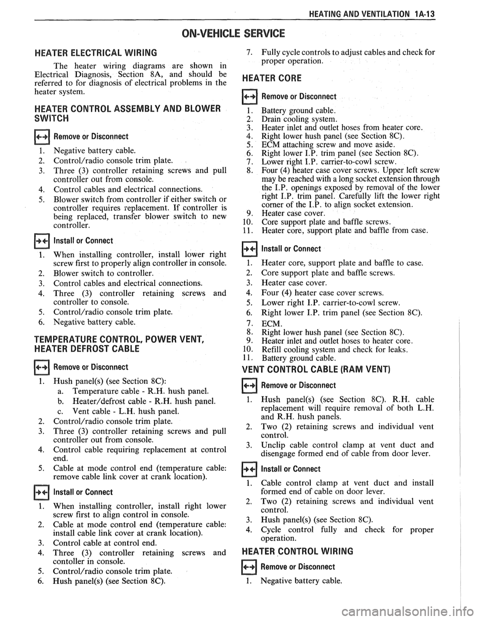
HEATER ELECTRICAL WIRING
The heater wiring diagrams are shown in
Electrical Diagnosis, Section
8A, and should be
referred to for diagnosis of electrical problems in the
heater system.
HEATER CONTROL ASSEMBLY AND BLOWER
SWITCH
Remove or Disconnect
1. Negative battery cable.
2.
Control/radio console trim plate.
3. Three
(3) controller retaining screws and pull
controller out from console.
4. Control cables and electrical connections.
5. Blower switch from controller if either switch or
controller requires replacement. If controller is
being replaced, transfer blower switch to new
controller.
Install or Connect
1. When installing controller, install lower right
screw first to properly align controller in console.
2. Blower switch to controller.
3. Control cables and electrical connections.
4. Three (3) controller retaining screws and
controller to console.
5. Control/radio console trim plate.
6. Negative battery cable.
TEMPERATURE CONTROL, POWER VENT,
HEATER DEFROST CABLE
Remove or Disconnect
1. Hush panel(s) (see Section 8C):
a. Temperature
cable - R.H. hush panel.
b.
Heateddefrost cable - R.H. hush panel.
c. Vent
cable
- L.H. hush panel.
2.
Control/radio console trim plate.
3. Three (3) controller retaining screws and pull
controller out from console.
4. Control cable requiring replacement at control
end.
5. Cable at mode control end (temperature cable:
remove cable link cover at crank location).
Install or Connect
1. When installing controller, install right lower
screw first to align control in console.
2. Cable
at mode control end (temperature cable:
install cable link cover at crank location).
3. Control cable at control end.
4. Three (3) controller retaining screws and
contoller in console.
5. Control/radio console trim plate.
6. Hush panel(s) (see Section 8C).
7. Fully cycle controls to adjust cables and check for
proper operation.
HEATER CORE
Remove or Disconnect
Battery ground cable.
Drain cooling system.
Heater inlet and outlet hoses from heater core.
Right lower hush panel (see Section
8C).
ECM attaching screw and move aside.
Right lower I.P. trim panel (see Section
8C).
Lower right I.P. carrier-to-cowl screw.
Four (4) heater case cover screws. Upper left screw
may be reached with a long socket extension through
the I.P. openings exposed by removal of the lower
right I.P. trim panel. Carefully lift the lower right
corner of the I.P. to align socket extension.
Heater case cover.
Core support plate and baffle screws.
Heater core, support plate and baffle from case.
Install or Connect
1. Heater core, support plate and baffle to case.
2. Core support
plate and baffle screws.
3. Heater case cover.
4. Four (4) heater case cover screws.
5. Lower right I.P. carrier-to-cowl screw.
6. Right lower I.P. trim panel (see Section 8C).
7. ECM.
8. Right lower hush panel (see Section
8C).
9. Heater inlet and outlet hoses to heater core.
10. Refill cooling system and check for leaks.
11. Battery ground cable.
VENT CONTROL CABLE (RAM VENT)
Remove or Disconnect 1
1. Hush panel(s) (see Section 8C). R.H. cable
replacement will require removal of both L.H.
and R.H. hush panels.
2. Two
(2) retaining screws and individual vent
control.
3. Unclip
cable control clamp at vent duct and
disengage formed end of cable from door lever.
1 Install or Connect
1. Cable control clamp at vent duct and install
formed end of cable on door lever.
2, Two (2) retaining screws and individual vent
control.
3. Hush
panel@) (see Section 8C).
4. Cycle
control fully and check for proper
operation.
HEATER CONTROL WIRING I
Remove or Disconnect
1. Negative battery cable.
Page 55 of 1825
18-12 AIR CONDITIONING
ELEGTRICAWACUUM SYSTEM
DIAGNOSIS
When diagnosing problems in the electrical sys-
tems of the air conditioning system, consult section
8A.
LEAK TESTING THE REFRIGERANT
SYSTEM
Whenever a refrigerant leak is suspected in the
system or a service operation performed which results
in disturbing lines or connections, it is advisable to
test for leaks.
Liquid Leak Detectors
There are a number of locations (fittings,
valves, etc.) on the air conditioning system where a
liquid leak detector solution may be used to pinpoint
refrigerant leaks.
By applying test solution to the area in question
with the swab that is attached to the bottle cap, bub-
bles will form within seconds if there is a leak.
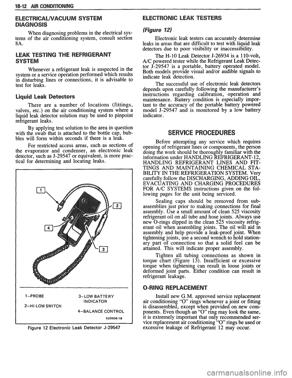
For restricted access areas, such as sections of
the evaporator and condenser, an electronic leak
detector, such as
5-29547 or equivalent, is more prac-
tical for determining and locating leaks.
3-LOW BATTERY
INDICATOR
2-HI-LOW SWITCH
4-BALANCE CONTROL
Figure 12 Electronic Leak Detector J-29547
ELECTRONIC LEAK TESTERS
(Figure 12)
Electronic leak testers can accurately determine
leaks in areas that are difficult to test with liquid leak
detectors due to poor visibility or inaccessibility.
The H-10 Leak Detector 5-26934 is a 110-volt,
A/C powered tester while the Refrigerant Leak Detec-
tor J-29547 is a portable, battery operated model.
Both models provide visual
and/or audible signals to
indicate leak detection.
The successful use of electronic leak detectors
depends upon carefully following the manufacturer's
instructions regarding calibration, operation and
maintenance. Battery condition is especially impor-
tant to the accuracy of the portable battery powered
model
5-29547 and is monitored by a low battery
indicator.
SERVICE PROCEDURES
Before attempting any service which requires
opening of refrigerant lines or components, the person
doing the work should be thoroughly familiar with the
information under HANDLING REFRIGERANT- 12,
HANDLING REFRIGERANT LINES AND FIT-
TINGS AND MAINTAINING CHEMICAL STA-
BILITY IN THE REFRIGERATION SYSTEM. Very
carefully follow the DISCHARGING, ADDING OIL,
EVACUATING AND CHARGING PROCEDURES
FOR
A/C SYSTEMS instructions given on the fol-
lowing pages for the unit being serviced.
Sealing caps should be removed from sub-
assemblies just prior to making connections for final
assembly. Use a small amount of clean 525 viscosity
refrigerant oil on all tube and hose joints. Always use
new O-rings dipped in the clean 525 viscosity refrig-
erant oil when assembling joints. The oil will aid in
assembly and help provide a leak-proof joint. When
tightening joints, use a second wrench to hold station-
ary part of connection so that
a solid feel can be
attained. This will indicate proper assembly.
Tighten all tubing connections as shown in
torque chart (Figure
13). Insufficient or excessive
torque when tightening can result in loose joints or
deformed joint parts. Either condition can result in
refrigerant leakage.
O-RING REPWCEMENT
Install new G. M. approved service replacement
air conditioning
"0" rings whenever a joint or fitting
is disassembled, except when provided on new com-
ponents. Even though an
"0" ring may look the same,
it is extremely important that only recommended ser-
vice replacement air conditioning
"0" rings be used or
excessive leakage of Refrigerant 12 may occur.
Page 196 of 1825
POWER STEERING 387-3
crocus cloth or fine hone. If the system 4. If the pump checks within specifications, leave
contains some dirt, flush it. If it is the valve open and turn (or have turned) the
exceptionally dirty, both the pump and the steering wheel into both corners. Record the
gear must be completely disassembled, highest pressures and compare with the
cleaned, flushed and reassembled before maximum pump pressure recorded. If this
further usage. pressure cannot be built in either (or one) side of
- the gear, the gear is leaking internally and must
c. If
the pressures recorded are constant, but
be disassembled and repaired. See "Unit Repair"
more than
100 PSI (690 kPa), below the
at the end of this section.
spec.9 rep1ace the flow 8. Shut off engine, remove testing gage, spare hose,
valve and recheck. If the pressures are still
low, replace the rotating group in the pump. reconnect pressure hose, check fluid
level and/or
make needed repairs.
ON-VEHICLE SERVICE
POWER STEERING GEAR
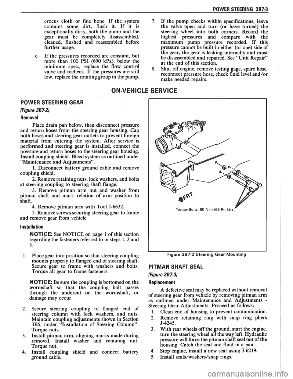
(Figure 387-2)
Removal
Place drain pan below, then disconnect pressure
and return hoses from the steering gear housing. Cap
both hoses and steering gear outlets to prevent foreign
material from entering the system. After service is
performed and steering gear is installed, connect the
pressure and return hoses to the steering gear housing.
Install coupling shield. Bleed system as outlined under
"Maintenance and Adjustments".
1. Disconnect battery ground cable and remove
coupling shield.
2. Remove retaining nuts, lock washers, and bolts
at steering coupling to steering shaft flange.
3. Remove pitman arm nut and washer from
pitman shaft and mark relation of arm position to
shaft.
4. Remove pitman arm with Tool J-6632.
5.
Remove screws securing steering gear to frame
and remove gear from vehicle.
Installation
NOTICE: See NOTICE on page 1 of this section
regarding the fasteners referred to in steps 1,2 and
3.
1. Place gear into position so that steering coupling
mounts properly to flanged end of steering shaft.
Secure gear to frame with washers and bolts.
Torque all gear to frame fasteners.
NOTICE: Be sure the coupling is bottomed on the
wormshaft so that the coupling bolt passes
through the undercut on the wormshaft, or
damage may occur.
2. Secure steering coupling to flanged end of
steering column with lock washers, and nuts.
Maintain coupling adjustments shown in Section
3B5, under "Installation of Steering Column".
Torque nuts.
3. Install pitman arm, aligning marks made during
removal. Install washer and retaining nut.
Torque nut.
4. Install coupling shield and connect battery
ground cable.
Torque Bolts: 90 Nm (66 Ft. ~bs.r
Figure 3B7-2 Steering Gear Mounting
PITMAN SHAFT SEAL
(Figure 387-3)
Replacement
A defective seal may be replaced without removal
of steering gear from vehicle by removing
pitman arm
as outlined under Maintenance and Adjustments
-
Steering Gear Adjustments. Proceed as follows:
1. Clean end of housing to prevent contamination.
2. Remove retaining
ring with snap ring pliers
J-4245.
3. With rear wheels off the ground, start the engine,
turn the steering wheel all the way left. Hydraulic
pressure will force the
pitman shaft seal out of the
housing. Catch the seal and fluid in a pan.
4. Stop engine, install a new seal using 5-6219.
5. Install seals/washers/snap rings.
Page 346 of 1825
ENGINE GENERAL INFORMATION 6-1
SECTION 6
NE GENERAL NFORMAT
Description ............................................................... 6 TBI ...................................... .. ...... 6E2 ................ Engine Mechanical Multi Port Fuel Injection (MPFI) 6E3 -
............................................... 2.8L V-6 ....................................................... 6A2 Exhaust Systems 6F
5.OL V-8 ......................................................... 6A3 ~~~~~~l ~~f~~~~ti~~ ..................................... 6-2
............................ Engine Cooling ...................................................... 6B Engine Performance Diagnosis 6-3 ............................. Engine Fuel 6C Engine Mechanical Diagnosis
6-3 ........................................................... ................................... Engine Knock Diagnosis 6-4
Engine Electrical ................................................... 6D Compression Test ...................................... ... 6-5
................... Driveability and Emission Controls ...................... 6E Oil Leak Detection .. ..................... 6-5
ALL NEW GENERAL MOTORS VEHICLES ARE CERTIFIED BY THE UNITED STATES
ENVIRONMENTAL PROTECTION AGENCY AS CONFORMING TO THE REQUIREMENTS OF
THE REGULATIONS FOR THE CONTROL OF AIR POLLUTION FROM NEW MOTOR VEHICLES.
THlS CERTIFICATION IS CONTINGENT ON CERTAIN ADJUSTMENTS BEING SET TO
FACTORY STANDARDS. IN MOST CASES, THESE ADJUSTMENT POINTS EITHER HAVE
BEEN PERMANENTLY SEALED AND/OR MADE INACCESSIBLE TO PREVENT
INDISCRIMINATE OR ROUTINE ADJUSTMENT IN THE FIELD. FOR
THlS REASON, THE
FACTORY PROCEDURE FOR TEMPORARILY REMOVING PLUGS, CAPS, ETC., FOR
PURPOSES OF SERVICING THE PRODUCT MUST BE STRICTLY FOLLOWED AND,
WHEREVER PRACTICABLE, RETURNED TO THE ORIGINAL INTENT OF THE DESIGN.
DESCRIPTION OF: SECTION 6
SECTION 6A - ENGINE MECHANICAL used for each carburetor. TBI units are described in
This section general contains information on the Section 6E.
mechanical parts of the engine, such as block,
crankshaft, pistons, valve train, and camshaft, that are
common to most engines. Overhaul procedures,
removal and replacement procedures, and
s~ecifications are also covered. Subsections furnish
detailed information on each specific engine. Service
SECTION 6D - ENG l N E ELECTRICAL
information is also given that relates to that engine's
use in each
Carline. Specific subsections are: Items
covered in this section are battery,
generator, starter, primary and secondary ignition,
6A2
- 2.8L V-6 Engine
engine wire harness, spark plugs and wires, and
6A3
- 5.OL V-8 Engine
ignition switch.
SECTION 6B - ENGINE COOLING
Engine cooling system components such as
radiator, water pump, thermostat, and cooling fan, are
covered in this section. Accessory drive belts are also
covered, along with cooling system capacities.
SECTION 6C - FUEL SYSTEM
This section contains information on all the parts
of the fuel system
except the carburetor, or Throttle
Body Injection unit (TBI) itself. Items covered are fuel
tank, fuel pump, and fuel lines. Specific subsections are
SECTION 6E - DRIVEABILITY AND EMISSIONS
This section covers emission control systems
general information, and diagnostic procedures which
will lead to repairing performance and driveability
related problems for gasoline engine equipped vehicles.
All emission components are covered, as well as all
removal and replacement procedures. Instructions on
use of special tools are also given. Specific sections are:
6E
- Driveability and Emissions
6E2
- Fuel Injection (TBI)
Page 358 of 1825
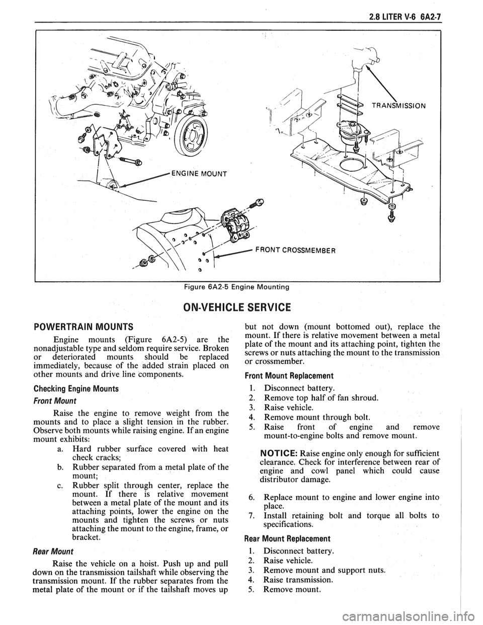
2.8 LITER V-6 6A2-7
I I Figure 6A2-5 Engine Mounting
ON-VEHICLE SERVICE
POWERTRAIN MOUNTS but not down (mount bottomed out), replace the
mount. If there is relative movement between a metal
Engine mounts (Figure 6A2-5) are the plate of the mount and its attaching point, tighten the nonadjustable type and seldom require service. Broken screws or nuts attaching the mount to the transmission or deteriorated mounts should be replaced or cross member^
immediately, because of the added strain placed on
other mounts and drive line components.
Front Mount Replacement
Checking Engine Mounts
1. Disconnect battery.
Front Mount 2. Remove top half of fan shroud.
3. Raise vehicle.
Raise the engine to remove weight from the
4. Remove mount through bolt. mounts and to place a slight tension in the rubber.
Observe both mounts while raising engine. If an engine 5. Raise front of engine and remove
mount exhibits: mount-to-engine
bolts and remove mount.
l
a. Hard rubber surface covered with heat
check cracks;
b. Rubber separated from a metal plate
of the
mount;
c. Rubber split through center, replace the
mount. If there is relative movement
between a metal plate of the mount and its
attaching points, lower the engine on the
mounts and tighten the screws or nuts
attaching the mount to the engine, frame, or
bracket.
Rear Mount
Raise the vehicle on a hoist. Push up and pull
down on the transmission tailshaft while observing the
transmission mount. If the rubber separates from the
metal plate of the mount or if the tailshaft moves up
NOTICE: Raise engine only enough for sufficient
clearance. Check for interference between rear of
engine and cowl panel which could cause
distributor damage.
6. Replace mount to engine and lower engine into
place.
7. Install retaining bolt and torque all bolts to
specifications.
Rear Mount Replacement
1. Disconnect battery.
2. Raise vehicle.
3. Remove mount and support nuts.
4. Raise transmission.
5. Remove mount.
Page 366 of 1825
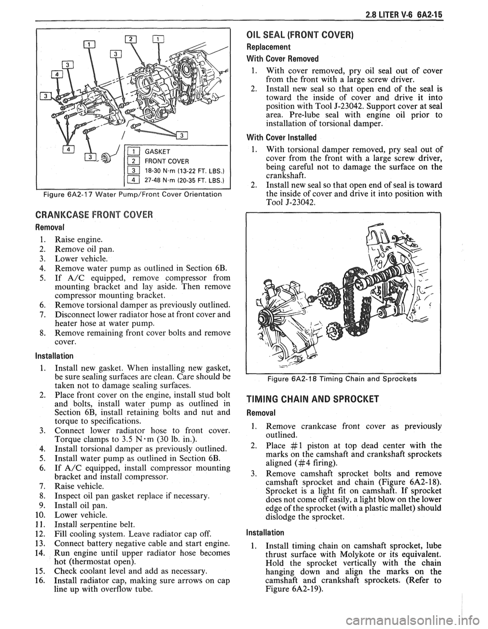
2.8 LITER V.6 6A2-15
18-30 N.m (13-22 FT. LBS.)
I 11 47-48 N.m (20-35 FT. LBS.) I
Figure 6A2-17 Water Pump/Front Cover Orientation
CRANKCASE FRONT COVER
Removal
1. Raise engine.
2. Remove oil pan.
3. Lower vehicle.
4. Remove water pump as outlined in Section 6B.
5. If A/C equipped, remove compressor from
mounting bracket and lay aside. Then remove
compressor mounting bracket.
6. Remove torsional damper as previously outlined.
7. Disconnect lower radiator hose at front cover and
heater hose at water pump.
8. Remove remaining front cover bolts and remove
cover.
Installation
1. Install new gasket. When installing new gasket,
be sure sealing surfaces are clean. Care should be
taken not to damage sealing surfaces.
2. Place front cover on the engine, install stud bolt
and bolts, install water pump as outlined in
Section 6B, install retaining bolts and nut and
torque to specifications.
3. Connect lower radiator hose to front cover.
Torque clamps to
3.5 N-m (30 lb. in.).
4. Install torsional damper as previously outlined.
5. Install water pump as outlined in Section 6B.
6. If A/C equipped, install compressor mounting
bracket and install compressor.
7. Raise vehicle.
8. Inspect oil pan gasket replace if necessary.
9. Install oil pan.
10. Lower vehicle.
11. Install serpentine belt.
12. Fill cooling system. Leave radiator cap off.
13. Connect battery negative cable and start engine.
14. Run engine until upper radiator hose becomes
hot (thermostat open).
15. Check coolant level and add as necessary.
16. Install radiator cap, making sure arrows on cap
line up with overflow tube.
OIL SEAL (FRONT COVER)
Replacement
With Cover Removed
1. With cover removed, pry oil seal out of cover
from the front with a large screw driver.
2. Install new seal so that open end of the seal is
toward the inside of cover and drive it into
position with Tool
5-23042. Support cover at seal
area. Pre-lube seal with engine oil prior to
installation of torsional damper.
With Cover Installed
1. With torsional damper removed, pry seal out of
cover from the front with a large screw driver,
being careful not to damage the surface on the
crankshaft.
2. Install new seal so that open end of seal is toward
the inside of cover and drive it into position with
To01 5-23042.
Figure 6A2-18 Timing Chain and Sprockets
TIMING CHAIN AND SPROCKET
Removal
1. Remove crankcase front cover as previously
outlined.
2. Place #1 piston at top dead center with the
marks on the camshaft and crankshaft sprockets
aligned (#4 firing).
3. Remove camshaft sprocket bolts and remove
camshaft sprocket and chain (Figure
6A2- 18).
Sprocket is a light fit on camshaft.
If sprocket
does not come off easily, a light blow on the lower
edge of the sprocket (with a plastic mallet) should
dislodge the sprocket.
Installation
1. Install timing chain on camshaft sprocket, lube
thrust surface with Molykote or its equivalent.
Hold the sprocket vertically with the chain
hanging down and align the marks on the
camshaft and crankshaft sprockets. (Refer to
Figure
6A2- 19).
Page 369 of 1825
6A2-18 2.8 LITER V-6
Installation
Clean sealing surfaces on cylinder case and oil
pan.
Install gasket and attach retaining bolts.
Remove jack and lower engine.
Install motor mount through bolts.
Install starter.
Install exhaust pipes.
Install converter dust cover.
Lower vehicle.
Install fan shroud.
Install distributor cap.
Refill crankcase.
Install air cleaner.
Connect battery.
Start engine, check for leaks.
OIL PUMP (FIGURE 6A2-22)
Removal
1. Remove oil pan as previously outlined.
2. Remove pump to rear main bearing cap bolt and
remove pump and extension shaft.
Disassembly
1. Remove
the pump cover attaching bolts and the
pump cover. Mark gear teeth so they may be
reassembled with the same teeth indexing.
2. Remove the idler gear and the drive gear and
shaft from the pump body.
3. Remove the pressure regulator valve retaining
pin pressure regulator spring and valve.
4. If the pickup screen and pipe assembly need
replacing, mount the pump in a soft-jawed vise
and extract pipe from pump cover. Do not disturb
the pickup screen on the pipe. This is serviced as
an assembly.
Cleaning and lnspection
1. Wash all parts in cleaning solvent and dry with
compressed air.
2. Inspect the pump body and cover for cracks or
excessive wear.
3. Inspect pump gears for damage or excessive wear.
The pump gears and body are not serviced
separately. If the pump gears or body are
damaged or worn, replacement of the entire oil
pump assembly is necessary.
4. Check the drive gear shaft for looseness in the
pump body.
5. Inspect inside of pump cover for wear that would
permit oil to leak past the ends of the gears.
6. Inspect the pickup screen and pipe assembly for
damage to screen or pipe.
7. Check the pressure regulator valve for fit.
Assembly
1. If the pickup screen and pipe assembly was
removed, it should be replaced with a new part.
Loss of press fit condition could result in an air
leak and loss of oil pressure. Mount the pump in
a soft-jawed vise, apply sealer to outside diameter of
swaged end of pipe, and using Tool
J-8369 tap
the pipe in place with a plastic hammer.
NOTICE: Be careful of twisting, shearing or
collapsing pipe while installing in pump.
2. Install the pressure regulator valve and related
parts.
3. Install the drive gear and shaft in the pump body.
4. Install the idler gear in the pump body in the
original orientation.
5. Install cover gasket.
6. Install the pump cover and torque attaching
screws to specifications.
7. Turn drive shaft by hand to check for smooth
operation.
Installation
1. Assemble pump and extension shaft with retainer
to rear main bearing cap, aligning top end of
hexagon extension shaft with hexagon socket
lower end of distributor drive gear.
2. Install pump to rear bearing cap bolt and torque
to specifications.
3. Install oil pan as previously outlined.
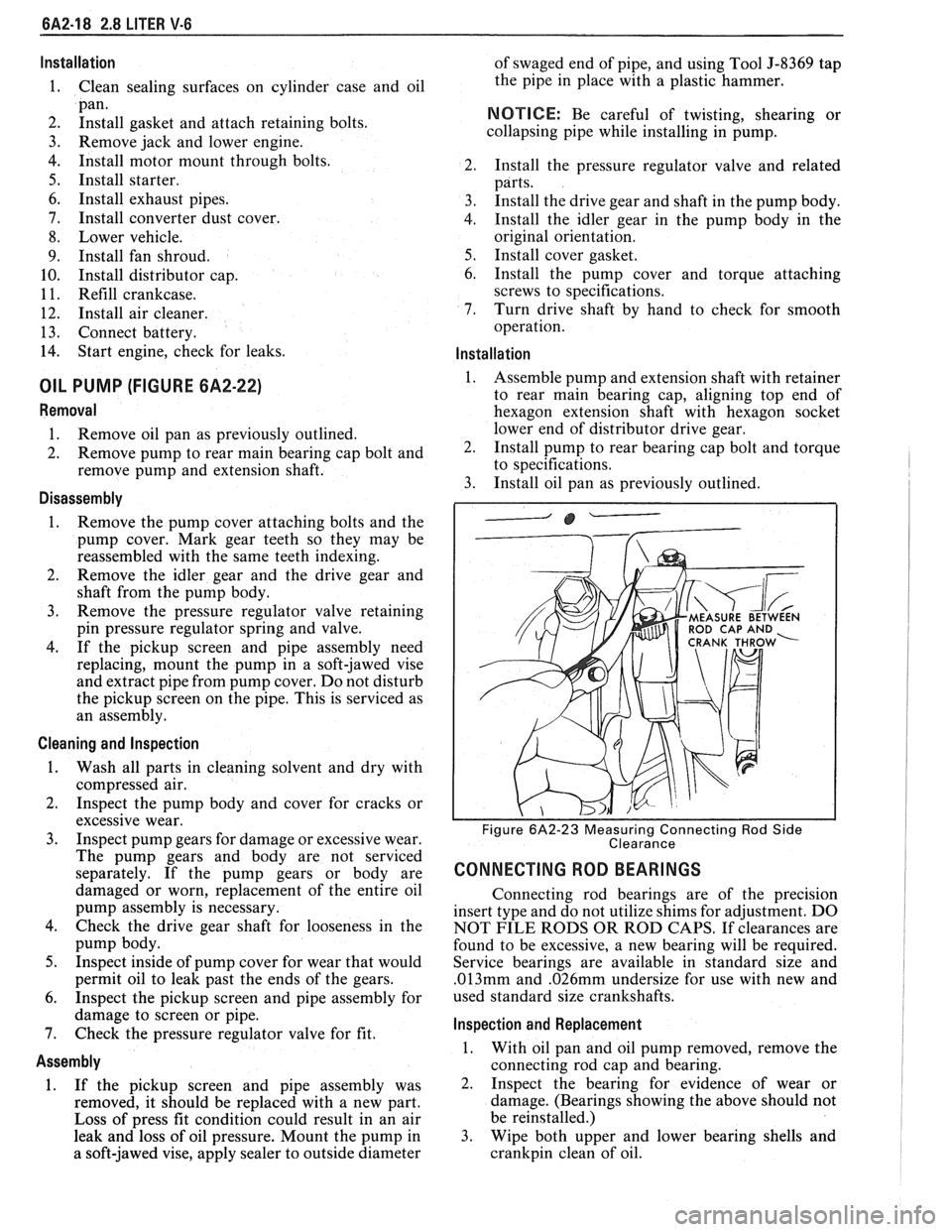
ROD CAP AND
Figure 6A2-23 Measuring Connecting Rod Side
Clearance
CONNECTING ROD BEARINGS
Connecting rod bearings are of the precision
insert type and do not utilize shims for adjustment. DO
NOT FILE RODS OR ROD CAPS. If clearances are
found to be excessive, a new bearing will be required.
Service bearings are available in standard size and
.013mm and .026mm undersize for use with new and
used standard size crankshafts.
lnspection and Replacement
1. With oil pan and oil pump removed, remove the
connecting rod cap and bearing.
2. Inspect the bearing for evidence of wear or
damage. (Bearings showing the above should not
be reinstalled.)
3. Wipe both upper and lower bearing shells and
crankpin clean of oil.
Page 406 of 1825
V-8 ENGINE 6A3-27
3. When finish honing
a cylinder bore to fit a piston,
the hone should be moved up and down at a
sufficient speed to obtain very fine uniform
surface finish marks in a cross-hatch pattern of
approximately
45" to 65" included angle. The
finish marks should be clean but not sharp, free
from imbedded particles and torn or folded
metal.
4. Permanently mark
the piston for the cylinder to
which it has been fitted and proceed to hone
cylinders and fit the remaining pistons.
NOTICE: Handle the pistons with care and do not
attempt to force them through the cylinder until
the cylinder has been honed to correct size as this
type piston can be distorted through careless
handling.
5. Thoroughly
clean the bores with hot water and
detergent. Scrub well with a stiff bristle brush and
rinse thoroughly with hot water. It is extremely
essential that a good cleaning operation be
performed. If any of the abrasive material is
allowed to remain in the cylinder bores, it will
rapidly wear the new rings and cylinder bores in
addition to the bearings lubricated by the
contaminated oil, the bores should be swabbed
and then wiped with a clean dry cloth. Cylinder
should not be cleaned with kerosene or gasoline.
Clean the remainder of the cylinder block to
remove the excess material spread during the
honing operation.
Piston Selection
1. Check USED piston to cylinder bore clearance as
follows:
a. Measure
the "Cylinder Bore Diameter"
with a telescope gage
"2-1/2" (64mm) from
top of cylinder bore").
b. Measure
the
"Piston Diameter" (at skirt
across center line of piston pin).
c. Subtract
piston diameter from cylinder bore
diameter to determine "Piston to Bore
Clearance".
d. Determine if piston to bore clearance is in
the acceptable range.
2. If
used piston is not acceptable, check Piston Size
Chart and determine if a new piston can be
selected to fit cylinder bore within the acceptable
range.
3. If
cylinder bore must be reconditioned, measure
new piston diameter (across center line of piston
pin) then hone cylinder bore to correct clearance
(preferable range).
4. Mark the piston to identify the cylinder for which
it was fitted.
OIL FILTER BYPASS VALVE
Inspection and Replacement
With the oil filter removed, check the spring and
fibre valve for operation. Inspect for a cracked or
broken valve. If replacement is necessary, the oil filter
adapter and bypass valve assembly must be replaced as an
assembly. Clean valve chamber in cylinder block
thoroughly. Torque retaining screws to specifications.
ENGINE ASSEMBLY
Removal
1. Disconnect battery.
2. Remove air cleaner.
3. Remove hood.
4. Drain radiator.
5. Remove lower radiator hose.
6. Remove upper fan shroud.
7. Remove upper radiator hose and coolant
recovery hose.
8. Remove transmission cooler lines.
9. Remove radiator.
10. Remove fan assembly.
1 1. Remove heater hoses.
12. Disconnect
carburetor linkage, includes cruise
control detent cable.
13. Remove vacuum brake booster line.
14. Remove
distributor cap and lay wiring aside.
15. Disconnect necessary wires and hoses.
16. Remove power steering
pump and lay aside.
17. Raise vehicle.
18. Remove exhaust
pipes at exhaust manifold.
19. Remove dust cover.
20. Remove converter bolts.
2 1. Disconnect starter wires.
22. Remove bell housing bolts.
23. Remove
motor mount through bolts.
24. Disconnect fuel lines
at fuel pump.
25. Lower vehicle.
26. Support transmission.
27. Remove
A.I.R./Converter pipe bracket.
28. Remove engine, include removing wire
from
bracket at rear left of engine.
Installation
1. Position engine
assembly in vehicle.
2. Attach
motor mount to engine brackets and
lower engine in place.
3. Remove engine lifting device.
4. Remove transmission floor jack.
5. Raise vehicle on hoist.
6. Install mount "through" bolts. Torque to
specifications.
7. Install bell housing bolts. Torque to
specifications.
8. On vehicles with automatic transmissions, install
I
converter to flywheel attaching bolts. Torque to
specifications.
9. Install flywheel splash shield of converter
housing cover as applicable. Torque attaching
bolts to specifications.
I
10. Install starter wires.
1 1. Connect fuel lines.
12. Connect exhaust pipe at manifold.
13. Lower vehicle on hoist.
14. Reinstall power steering pump, if so equipped.
15. Connect necessary wires and hoses.
Page 407 of 1825
6A3-28 V-8 ENGINE
16. Install
radiator and fan shroud and reconnect
radiator and heater hoses.
17. Fill cooling system.
18. Fill
crankcase with oil. See owner's manual for
specifications.
19. Install air cleaner.
20. Install hood.
21. Connect battery cables.
NOTICE: To avoid possible arcing of battery,
connect positive battery cable first.
22. Start engine, check for leaks and check timing.
CRANKSHAFT
The crankshaft can be removed while the engine
is disassembled for overhaul, as previously outlined, or
without complete disassembly.
Removal
With the engine removed from the vehicle and the
transmission and/or clutch housing removed
from the engine, mount engine in stand and
clamp securely.
Remove the oil dip stick and oil dip stick tube, (if
applicable).
Remove the starting motor, clutch assembly (if
equipped) and flywheel.
Remove the spark plugs.
Remove crankshaft pulley and torsional damper.
Remove oil pan and oil pump.
Remove crankcase front cover, and if so
equipped, remove timing chain and camshaft
sprocket.
Check the connecting rod caps for cylinder
number identification. If necessary, mark them.
Remove the connecting rod caps and push the
pistons to top of bores.
Remove main bearing caps and lift crankshaft out
of cylinder block.
Remove rear main bearing oil seal and main
bearings from cylinder block and main bearing
caps.
Cleaning and Inspection
1. Wash crankshaft in solvent and dry with
compressed air.
2. Measure dimensions of main bearing journals and
crankpins with a micrometer for out-of-round,
taper or undersize. (See Specifications.) 3.
Check crankshaft for run-out by supporting at
the front and rear main bearings journals in
"V"
blocks and check at the front and rear
intermediate journals with a dial indicator. (See
Specifications.)
4. Replace or recondition the crankshaft if out of
specifications.
SPROCKET OR GEAR REPLACEMENT
e Remove crankshaft sprocket using Tool
5-5825, install using Tool J-5590.
Installation
1.
Install rear main bearing oil seal in cylinder block
and rear main bearing cap grooves. Install with
lip of seal toward front of engine. Where seal has
two lips install lip with helix towards front of
engine.
2. Lubricate lips of seal with engine oil. Keep oil off
parting line surface.
3. Install main bearings in cylinder block and main
bearing caps then lubricate bearing surface with
engine oil.
4. Install crankshaft, being careful not to damage
bearing surfaces.
5. Recheck bearing clearances using plastigage.
6. Apply a thin coat of brush-on type oil sealing
compound to block mating surface and
corresponding surface of cap only. Do not allow
sealant on crankshaft or seal.
7. Install main bearing caps with arrows pointing
toward front of engine.
8. Torque all except rear main bearing cap bolts to
specifications. Torque rear main bearing cap bolts
to 10-12 lbs. ft. (14-16
N.m)then tap end of
crankshaft, first rearward then forward with a
lead hammer. This will line up rear main bearing
and crankshaft thrust surfaces.
Retorque all main
bearing cap bolts to specifications.
9. Measure crankshaft end play with a feeler gage.
Force crankshaft forward and measure clearance
between the front of the rear main bearing and the
crankshaft thrust surface.
10. Install flywheel and torque to specifications. A
wood block placed between the crankshaft and
cylinder block will prevent crankshaft from
rotating.
Align dowel hole in flywheel with dowel
hole in crankshaft. On vehicles equipped
with automatic transmissions, install
flywheel with the converter attaching pads
towards transmission.
GENERAL DATA
TYPE .................................................................................................................................. 90" V-8
DISPLACEMENT
............................................................................... 305 Cu. In., 350 Cu. In.
......................................................... LITER (VIN) ................................... ...... 5.0, (E), (F), 5.7 (8)
RPO ......................................................................................................................... L03, LB9, L98
BORE ........................................................................................................................ 3.736, 4.000
STROKE
........................... .. ....................................................................................... 3.480, 3.480
COMPRESSION RATIO
................................................................................... 931, 931, 9.5:1
FIRING ORDER .................................................................................................... 1-8-4-3-6-5-7-2
Page 425 of 1825
6B-I4 ENGINE COOLING
SMALL
586826
Fig. 26 Removing Oil Cooler Gasket
4. Remove old rubber gaskets, throw away, clean
and dry seal areas.
5. Place rubber gaskets on a new oil cooler and place
onto outlet tank fitting holes, being careful not to
loosen or misalign gaskets. Gaskets must be
installed dry and free of dirt and oil.
6. Install
and tighten nuts snugly onto fittings.
7. Torque nuts
to 20
N.m (15 lb. ft.). Overtorquing
could cut the rubber gaskets.
8. Replace
tank as previously described.
9. Test radiator.
Recore
If the radiator core is damaged beyond repair and
the other parts are serviceable, install the original inlet
and outlet tanks, oil cooler, radiator cap, and drain
valve, onto a new core and install new gaskets.
Drain Cock
Oil Cooler Replacement If the drain cock does not seal when tightened
snugly, remove the drain cock, clean drain and replace.
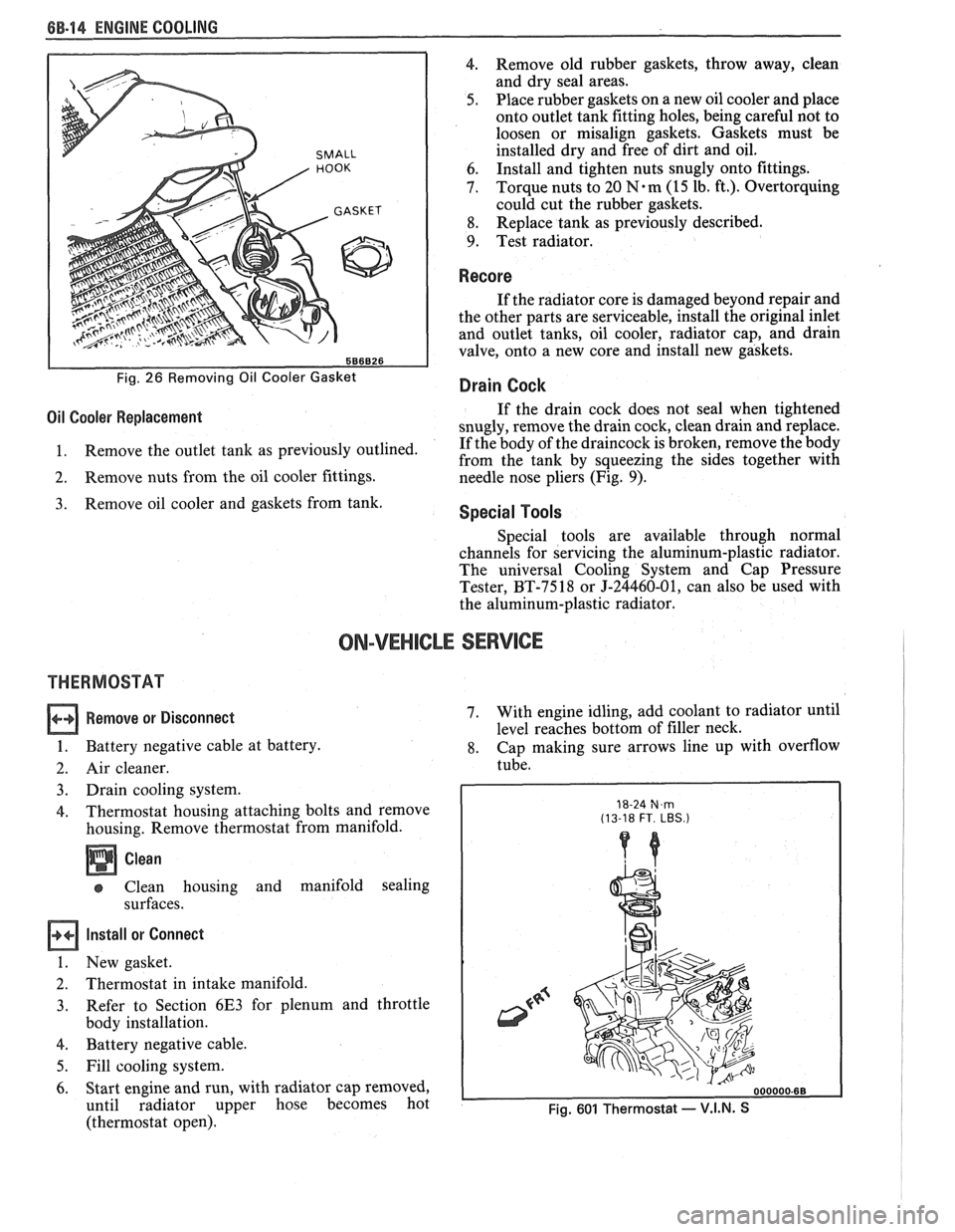
1. Remove
the outlet tank as previously outlined. If
the body of the draincock is broken, remove the body
from the tank by squeezing the sides together with
2. Remove nuts from the oil cooler fittings.
needle nose pliers (Fig. 9).
Remove oil cooler and gaskets from tank. Special Tools
Special tools are available through normal
channels for servicing the aluminum-plastic radiator.
The universal Cooling System and Cap Pressure
Tester, BT-7518 or J-24460-01, can also be used with
the aluminum-plastic radiator.
ON-VEHICLE SERVICE
THERMOSTAT
Remove or Disconnect
1. Battery negative cable at battery.
2. Air cleaner.
3. Drain cooling system.
4. Thermostat housing attaching bolts and remove
housing. Remove thermostat from manifold.
Clean
Clean housing and manifold sealing
surfaces.
Install or Connect
1. New gasket.
2. Thermostat in intake manifold.
3. Refer
to Section 6E3 for plenum and throttle
body installation.
4. Battery negative cable.
5. Fill cooling system.
6. Start engine and run, with radiator cap removed,
until radiator upper hose becomes hot
(thermostat open). 7.
With
engine idling, add coolant to radiator until
level reaches bottom of filler neck.
8. Cap making sure arrows line up with overflow
tube.
18-24 N,m (13-18 FT. LBS.)
Fig. 601 Thermostat - V.I.N. S