brake sensor PONTIAC FIERO 1988 Service Repair Manual
[x] Cancel search | Manufacturer: PONTIAC, Model Year: 1988, Model line: FIERO, Model: PONTIAC FIERO 1988Pages: 1825, PDF Size: 99.44 MB
Page 16 of 1825
- -
GENERAL INFORMATION OA-13
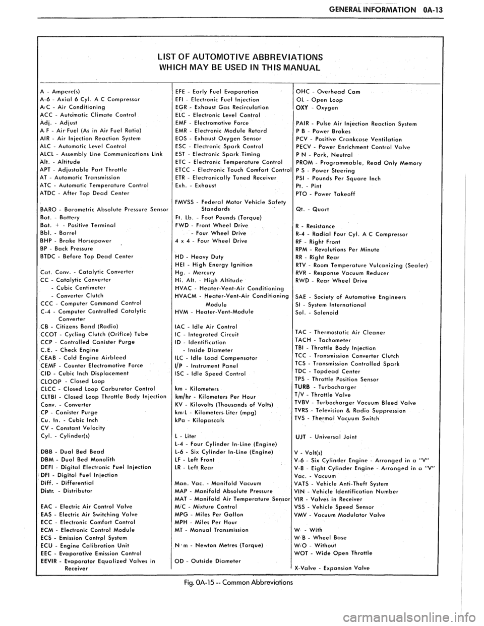
LIST OF AUTOMOTIVE ABBREVIATIONS
WHICH MAY
BE USED IN THIS MANUAL
A-6 - Axial 6 Cyl. A C Compressor AIC - Air Conditioning
ACC - Auto'matic Climate Control
EMF
- Electromotive Force PAIR - Pulse Air Injection Reaction System
EMR - Electronic Module Retard
P B - Power Brakes
EOS - Exhaust Oxygen Sensor
PCV - Positive Crankcase Ventilation
ESC - Electronic Spark Control
PECV - Power Enrichment Control Valve
APT
- Adjustable Part Throttle
AT - Automatic Transmission
ATC - Automatic Temperature Control
ATDC
- After Top Dead Center
FMVSS
- Federal Motor Vehicle Safety BAR0 - Barometric Absolute Pressure Sensor
Ft. Lb. - Foot Pounds (Torque)
Bat. + - Positive Terminal FWD - Front Wheel Drive
- Four Wheel Drive
BHP - Brake Horsepower 4 x 4 - Four Wheel Drive
BP - Back Pressure
BTDC - Before Top Dead Center
HD - Heavy Duty HE1 - High Energy Ignition
Cat. Conv. - Catalytic Converter
CC - Catalytic Converter
- Cubic Centimeter - Converter Clutch
CCC - Computer Command Control
HVM
- Heater-Vent-Module
IAC
- ldle Air Control CCOT - Cycling Clutch (Orifice) Tube IC - Integrated Circuit CCP - Controlled Canister Purge
ID - Identification
C.E. - Check Engine - Inside Diameter
CEAB - Cold Engine Airbleed ILC - Idle Load Compensator
CEMF - Counter Electromotive Force I/P - Instrument Panel
CID - Cubic Inch Displacement ISC - Idle Speed Control CLOOp - Closed Loop
CLCC - Closed Loop Carburetor Control km - Kilometers
CP
- Canister Purge kmiL - Kilometers Liter (mpg) Cu. In. - Cubic Inch kPa - Kilopascals
CV - Constant Velocity
Cyl.
- Cylinder(s)
L-4 - Four Cylinder In-Line (Engine)
DBB - Dual Bed Bead L-6 - Six Cylinder In-Line (Engine)
DBM - Dual Bed Monolith
LF - Left Front DEFl - Digital Electronic Fuel Injection LR - Left Rear DFI - Digital Fuel Injection
Diff. - Differential Man. Vac. - Manifold Vacuum Distr. - Distributor MAP - Manifold Absolute Pressure
EAC
- Electric Air Control Valve
EAS - Electric Air Switching Valve MPG - Miles Per Gallon
ECC - Electronic Comfort Control
MPH - Miles Per Hour
ECM - Electronic Control Module MT - Manual Transmission
N.m - Newton Metres (Torque)
Emission Control
Fig. 014-15 -- Common Abbreviations
Page 318 of 1825
DISC BRAKE CALIPER ASSEMBLY 581-3
a Measure
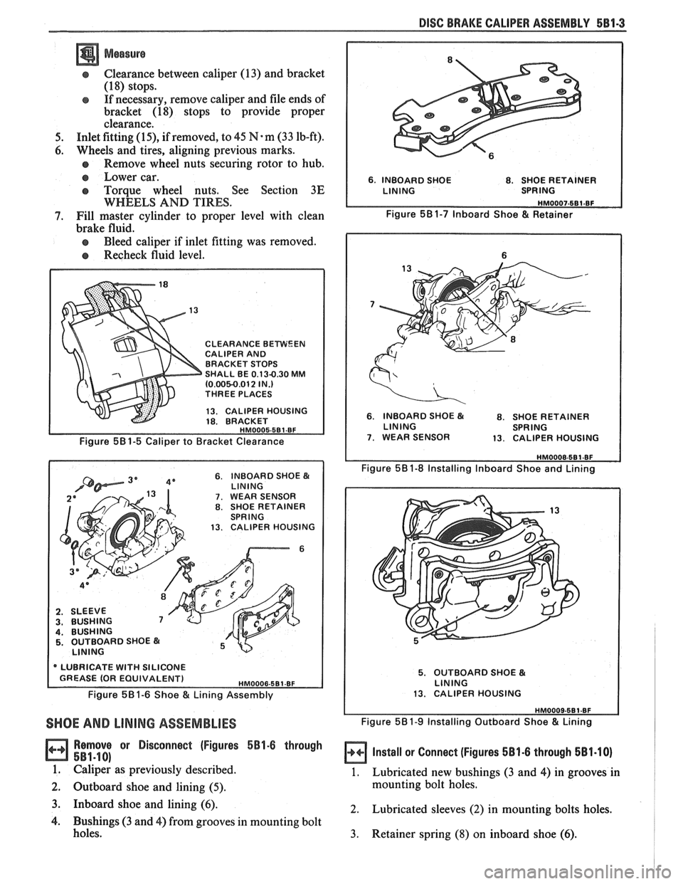
Clearance between caliper (13) and bracket
(1 8) stops.
If necessary, remove caliper and file ends of
bracket
(18) stops to provide proper
clearance.
5. Inlet fitting (15), if removed, to 45 N-m (33 lb-ft).
6. Wheels and tires, aligning previous marks.
Remove wheel nuts securing rotor to hub.
e Lower car.
e Torque wheel nuts. See Section 3E
WHEELS AND TIRES.
7. Fill master cylinder to proper level with clean
brake fluid.
Bleed caliper if inlet fitting was removed.
Recheck fluid level.
CLEARANCE BEWEEN CALIPER AND
BRACKET STOPS
SHALL BE
0.13-0.30 MM (0.0050.012 IN.) THREE PLACES
13. CALIPER HOUSING
18. BRACKET
Figure 581-5 Caliper to Bracket Clearance
6. INBOARD SHOE B( LlNlNG 7. WEAR SENSOR 8. SHOE RETAINER
SPRING
13. CALIPER HOUSING
6
2. SLEEVE 3. BUSHING 4. BUSHING 5. OUTBOARD SHOE
LlNlNG
* LUBRICATE WITH SILICONE
Figure 58 1-6 Shoe & Lining Assembly
SHOE AND LINING ASSEMBLIES
Remove or Disconnect (Figures 5B1-6 through
581-18)
1. Calipe; as previously described.
2. Outboard shoe and lining
(5).
6, INBOARD SHOE 8. SHOE RETAINER
Figure 581-7 lnboard Shoe & Retainer
6. INBOARD SHOE B( 8. SHOE RETAINER
LINING SPRING
7. WEAR SENSOR 13. CALIPER HOUSING
Figure 581-8 Installing lnboard Shoe and Lining
5. OUTBOARD SHOE & LINING
13. CALIPER HOUSING
Figure 581-9 Installing Outboard Shoe & Lining
Install or Connect (Figures 581.6 through 581.10)
1. Lubricated new bushings (3 and 4) in grooves in
mounting bolt holes.
3. Inboard shoe and lining (6). 2. Lubricated sleeves (2) in mounting bolts holes.
4. Bushings (3 and 4) from grooves in mounting bolt
holes.
3. Retainer spring (8) on inboard shoe (6).
Page 319 of 1825
5814 DISC BRAKE CALIPER ASSEMBLY .
4. Inboard shoe and lining (6) by snapping retainer
spring (8) into piston (1) ID. Wear sensor (7)
should be at the leading edge of shoe during
forward wheel rotation. Shoe must lay flat against
piston.
5. Outboard
shoe and lining (5). Back of shoe must
lay flat against caliper.
6. Caliper as previously described.
7. Apply approximately
778
N (175 lb) force three
times to brake pedal to seat linings.
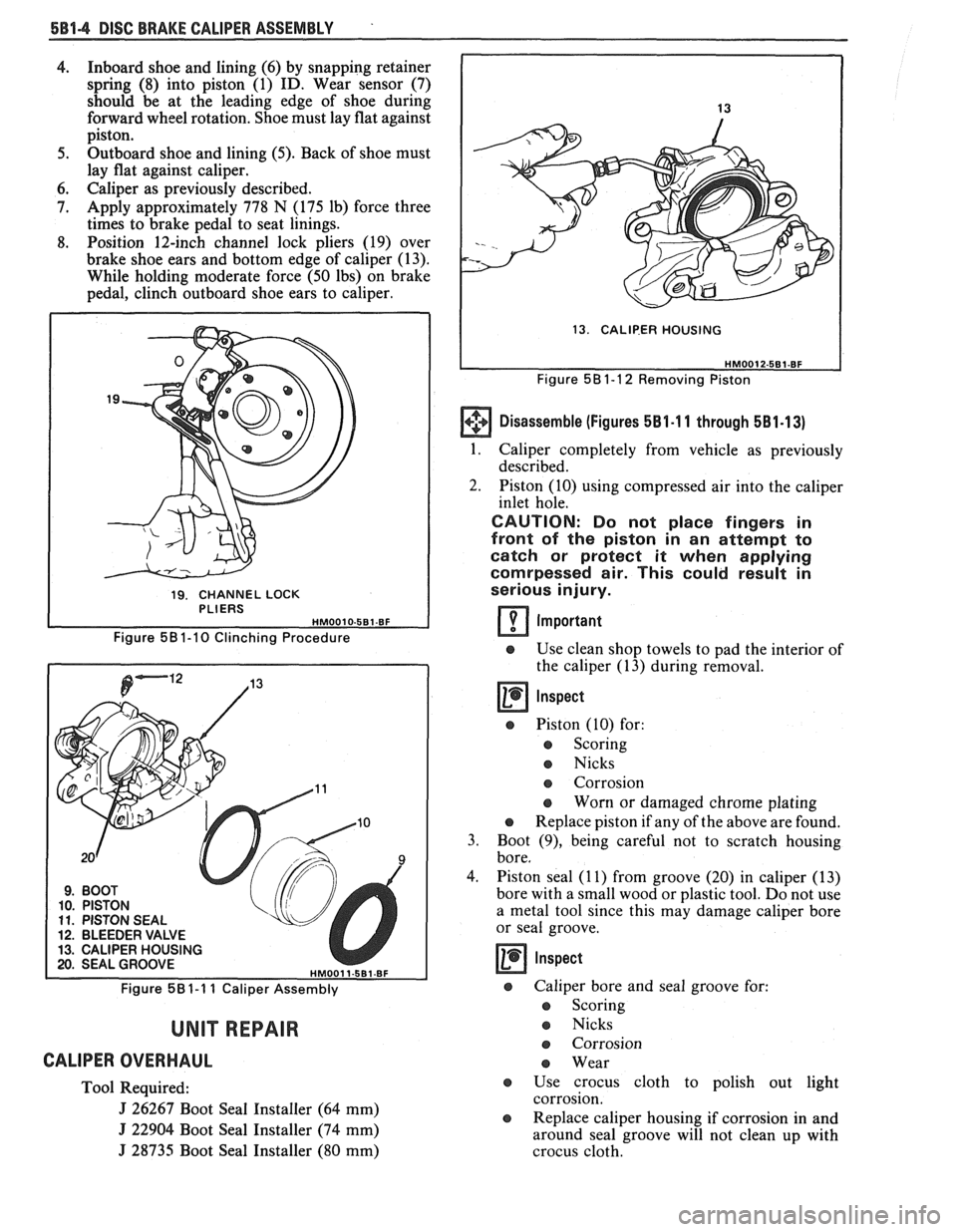
8. Position 12-inch channel lock pliers (19) over
brake shoe ears and bottom edge of caliper (13).
While holding moderate force (50 Ibs) on brake
pedal, clinch outboard shoe ears to caliper.
19. CHANNEL LOCK
PLIERS
Figure 58 1-1 0 Clinching Procedure
9. BOOT 10. PISTON 11. PISTON SEAL 12. BLEEDER VALVE 13. CALIPER HOUSING 20. SEAL GROOVE HMO01 1-5B1-BF
Figure 581-1 1 Caliper Assembly
UNIT REPAIR
CALIPER OVERHAUL
Tool Required:
J 26267 Boot Seal Installer (64 mm)
J 22904 Boot Seal Installer (74 mm)
J 28735 Boot Seal Installer (80 mm)
I
13. CALlP-ER HOUSING
I
Figure 58 1-1 2 Removing Piston
Disassemble (Figures 581-1 1 through 5B1-13)
1. Caliper completely from vehicle as previously
described.
2. Piston (10) using compressed air into the caliper
inlet hole.
CAUTION: Do not place fingers in
front of the piston in an attempt to
catch or protect it when applying
comrpessed air. This could result in
serious injury.
Important
e Use clean shop towels to pad the interior of
the caliper (13) during removal.
@ Piston (10) for:
e Scoring
Nicks
e Corrosion
e Worn or damaged chrome plating
e Replace piston if any of the above are found.
3. Boot (9), being careful not to scratch housing
bore,
4. Piston seal
(1 1) from groove (20) in caliper (13)
bore with a small wood or plastic tool. Do not use
a metal tool since this may damage caliper bore
or seal groove.
Inspect
@ Caliper bore and seal groove for:
e Scoring
e Nicks
e Corrosion
Wear
e Use crocus cloth to polish out light
corrosion.
@ Replace caliper housing if corrosion in and
around seal groove will not clean up with
crocus cloth.
Page 322 of 1825
DISC BRAKE CALIPER ASSEMBLY 586-1
SEC"619RI 5B6
SC BRAKE CAL PER ASSEMBLY
3548 SERIES
CONTENTS
General Description ................................. 5B6-2 Unit Repair ........................................... 5B6-5
On-Car Service ........................................ 5B6-2 Caliper Overhaul ....................................... 5B6-5
Caliper Assembly ....................................... 5B6-2
Parking Brake Adjustment ......................... 5B6-3
Shoe and Lining Assembly ......................... 5B6-4
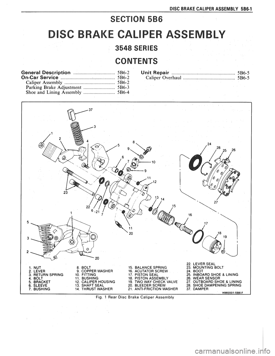
22 LEVER SEAL
1. NUT
2. LEVER
3. RETURN SPRING 4. BOLT 5. BRACKET 8.
BOLT 15.
BALANCE SPRING
23. MOUNT~NG BOLT 9. COPPER WASHER 16. ACUTATOR SCREW 24. BOOT
10 FITTING 17.
PISTON SEAL 25. INBOARD SHOE & LINING 11. BUSHING 18. PISTON ASSEMBLY 26. WEAR SENSOR
12. CALIPER HOUSING 19. TWO
WAY CHECK VALVE 27. OUTBOARD SHOE & LINING 6. SLEEVE 13. SHAFT SEAL 20. BLEEDER SCREW 28. SHOE DAMPENING SPRING 7. BUSHING 14. THRUST WASHER 21. ANTI.FRICTION WASHER 37. DAMPER HM0001-566-F
Fig. 1 Rear Disc Brake Caliper Assembly
Page 325 of 1825
e Remove lug nuts securing rotor to hub.
e Lower car.
o Torque lug nuts. See WHEELS AND
TIRES.
SHOE AND LINING ASSEMBLIES
Figures 5 thru 8
Remove or Disconnect
1. Caliper as previously described.
2 Outboard shoe and lining (27) (Figure 5).
Install or Connect
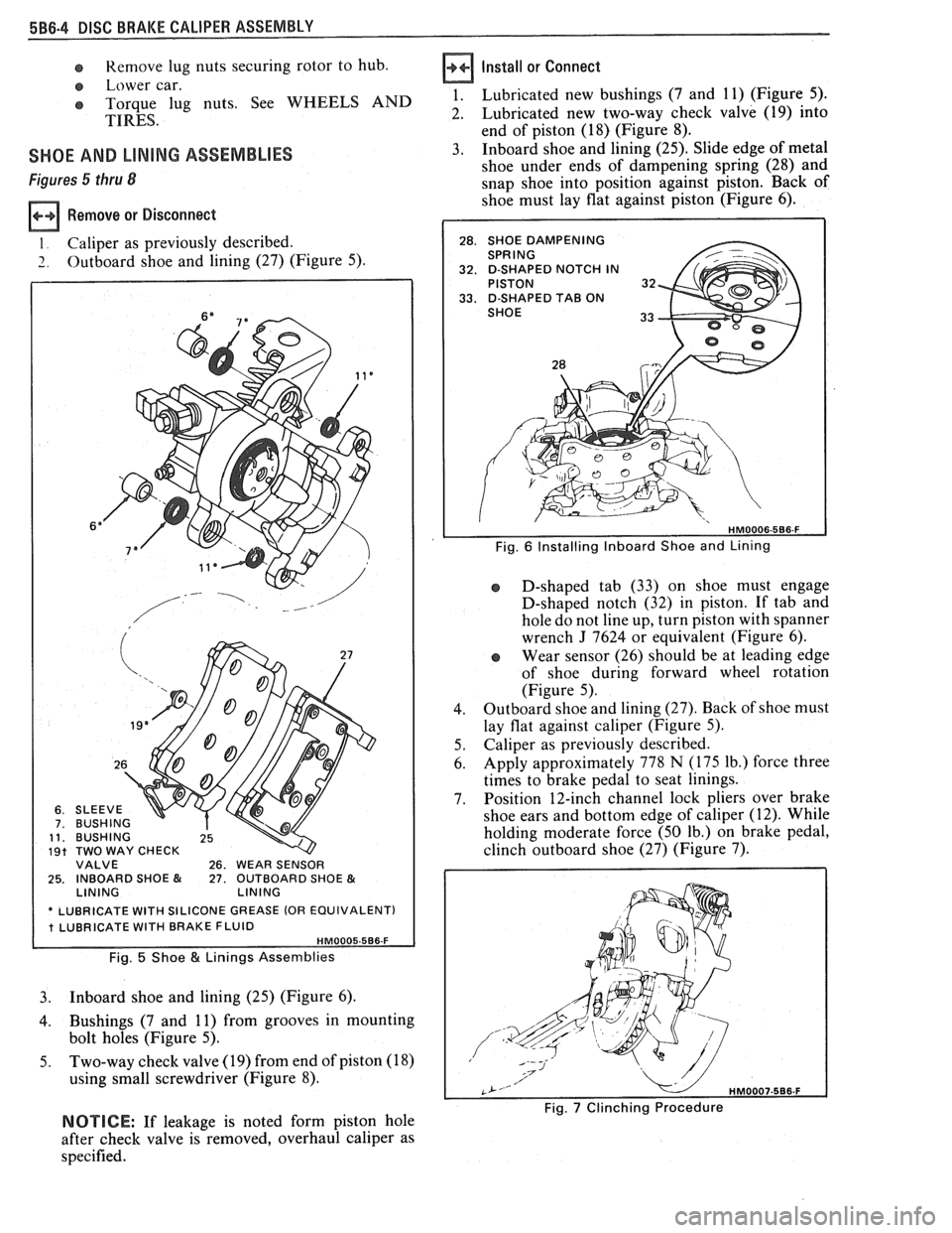
1. Lubricated new bushings (7 and 11) (Figure 5).
2. Lubricated new two-way check valve (19) into
end of piston (18) (Figure 8).
3. Inboard shoe and lining (25). Slide edge of metal
shoe under ends of dampening spring (28) and
snap shoe into position against piston. Back of
shoe must lay flat against piston (Figure 6).
Fig. 6 Installing Inboard Shoe and Lining
26. WEAR SENSOR 25. INBOARD SHOE & 27. OUTBOARD SHOE & LINING
ASE (OR EQUIVALENT)
Fig. 5 Shoe & Linings Assemblies
3. Inboard shoe and lining (25) (Figure 6).
4. Bushings (7 and 11) from grooves in mounting
bolt holes (Figure 5).
5. Two-way check valve (19) from end of piston (18)
using small screwdriver (Figure 8). D-shaped
tab (33) on shoe must engage
D-shaped notch (32) in piston. If tab and
hole do not line up, turn piston with spanner
wrench
J 7624 or equivalent (Figure 6).
r, Wear sensor (26) should be at leading edge
of shoe during forward wheel rotation
(Figure 5).
4. Outboard
shoe and lining (27). Back of shoe must
lay flat against caliper (Figure
5).
5. Caliper as previously described.
6. Apply approximately 778
N (175 lb.) force three
times to brake pedal to seat linings.
7. Position
12-inch channel lock pliers over brake
shoe ears and bottom edge of caliper (12). While
holding moderate force
(50 lb.) on brake pedal,
clinch outboard shoe (27) (Figure 7).
NOTICE: If leakage is noted form piston hole
after check valve is removed, overhaul caliper as
specified.
Page 626 of 1825
DRIVEABILITY AND EMISSIONS - 5.0L (VIM E) 6E2-C8-1
SECTION C8
"FRANSMISSIBN CONVERnEW CLUTCH (TCC) SYSTEM
CONTENTS
GENERAL DESCRIPTION ............... C8-1 RESULTS OF INCORRECT TCC
PURPOSE
........................ C8-1 OPERATION ..................... C8-2
......................... OPERATION ...................... C8-1 DIAGNOSIS CS-2
.................... CIRCUIT DESCRIPTION ....e.e..eea..e C8-1 ON-CAR SERVICE C8-2
................. PARTS INFORMATION C8-2
GENERAL DESCRIPTION
PURPOSE
The transmission converter clutch (TCC) system
is designed to eliminate power loss by the converter
(slippage) thus increasing fuel economy. By locking
the converter clutch,
a more effective coupling to the
flywheel is achieved. The converter clutch is operated
by an ECM controlled solenoid.
OPERATION
Engagement of the TCC is accomplished by a
solenoid operated valve within the transmission. The
solenoid is activated when an internal switch in the
ECM is grounded. Although the ECM may command
the TCC
"ON", the converter clutch will not apply
until internal transmission fluid pressure require-
ments are met. See Section
"7A".
Before the ECM activates the TCC apply solenoid,
several inputs must be monitored:
e Vehicle Speed. Must be above a certain value
before the TCC can be applied.
Coolant Temperature. The engine coolant
temperature must be above a certain value
before the TCC can be applied.
@ Throttle Position Sensor. After the TCC is
applied, during low engine load condition, the
ECM uses the information from the TPS to
release the clutch when the car is accelerating
or decelerating at a certain rate.
CIRCUIT DESCRIPTION
When the brake pedal is not depressed (switch
closed), battery voltage will be fed to the TCC
solenoid. If the ECM has determined that conditions
are correct, the circuit from the TCC solenoid will be
completed to ground through the ECM and the TCC
solenoid will be activated.
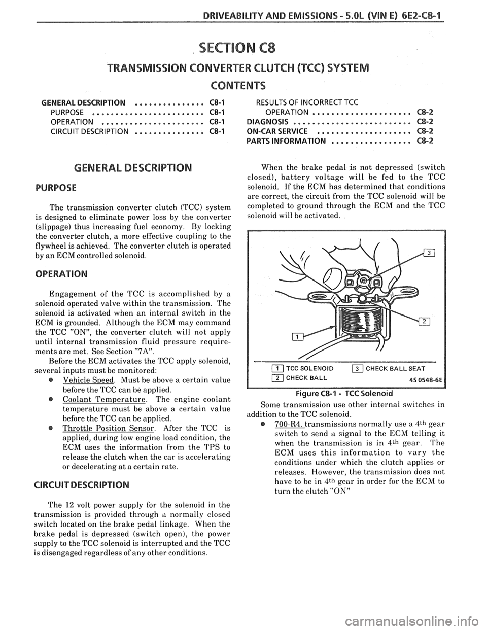
Figure C8-1 - TCC Solenoid
Some transmission use other internal switches in
addition to the TCC solenoid.
@ 700-R4. transmissions normally use a 4th gear
switch to send
a signal to the ECM telling it
when the transmission is in
4th gear. The
ECM uses this information to vary the
conditions under which the clutch applies or
releases. However, the transmission does not
have to be in
4th gear in order for the ECM to
turn the clutch
"ON"
The 12 volt power supply for the solenoid in the
transmission is provided through
a normally closed
switch located on the brake pedal linkage. When the
brake pedal is depressed (switch open), the power
supply to the TCC solenoid is interrupted and the TCC
is disengaged regardless of any other conditions.
Page 627 of 1825
6Ef-C8-2 BRlVEABlLlYV AND EMISSIONS - 5.OL (VIN E) ----
RESULTS OF INCORRECTTCC OPERATION
An engine stall will result if the converter clutch
remains applied at all times.
If the converter clutch does not apply, fuel
economy may be lower than expected.
The transmission converter clutch
(TCC) system
has different operating characteristics than an
automatic transmission without TCC.
If the driver
complains of a "chuggle" or "surge" condition, the car
should be road tested and compared to a similar car to
see if a real problem exists. Another TCC complaint
may be
a downshift felt when going up a grade,
especially with cruise control. This may not be
a
downshift, but a clutch disengagement due to the
change in TPS to maintain cruising speed. The
Owner's Manual section on TCC operation should be
reviewed with the driver.
DIAGNOSIS
The diagnosis of the TCC system is covered in
ClIART C-8. If the ECM detects a problem in the VSS
system, a Code
24 should set. In this case see Code 24
Chart.
If the ECM doesn't switch the TCC "ON" when
driving, but will turn it
"ON" when the "test"
terminal is grounded with ignition "ON" and engine
stopped, the sensors such as coolant, speed, and
throttle position should be checked.
ON-CAW SERVICE
@ See Section "7" for TCC Solenoid.
@ See Section "SH" for VSS (HP mounted) and brake
system.
PAR- SNFORMATBIQN
PART NAME GRQUQ
.......................... Sensor, VSS 9.761
........................ Solenoid, TCC 4.122
Page 629 of 1825
6EZ-C8-4 DRIVEABILITY AND EMISSIONS - 5.OL (VIN E)
I5 WAY (FRONT VIEW)
SPEED INPUT
4rH GEAR SIGNAL
422 TANIBLK
ALDL CONNECTOR
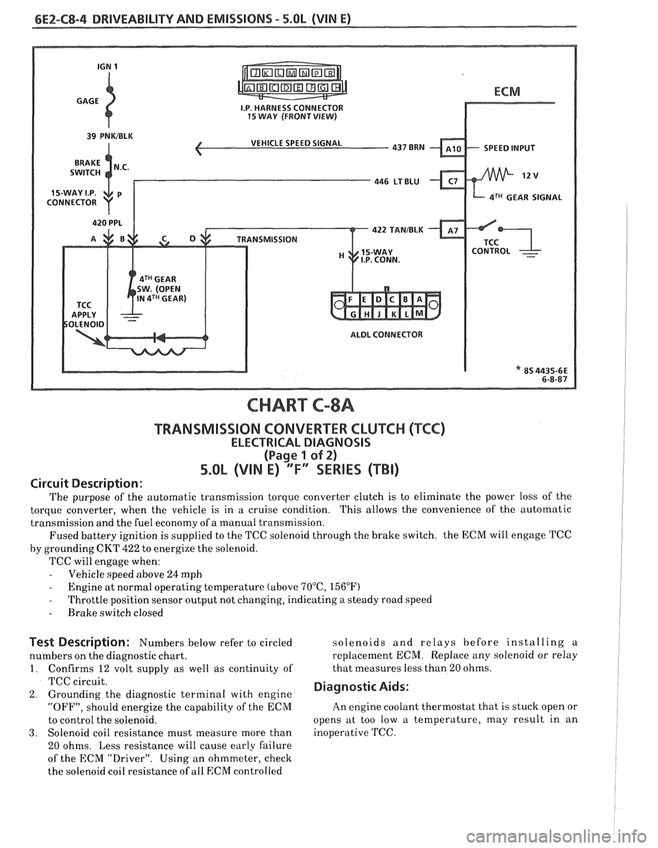
CHART C-8A
TRANSMISSION CONVERTER CLUTCH (TCC)
ELECTRICAL DIAGNOSIS
(Page 1 of 2)
5.OL (VIN E) "F" "SERIES (TBI)
Circuit Description:
The purpose of the automatic transmission torque converter clutch is to eliminate the power loss of the
torque converter, when the vehicle is in a cruise condition. This allows the convenience of the automatic
transmission and the fuel economy of a manual transmission.
Fused battery ignition is supplied to the TCC solenoid through the brake switch. the ECM will engage
TCC
by grounding CKT 422 to energize the solenoid.
TCC will engage when:
- Vehicle speed above 24 mph - Engine at normal operating temperature (above 70°C, 156°F)
- Throttle position sensor output not changing, indicating a steady road speed
- Brake switch closed
Test Description: Numbers below refer to circled solenoids
and relays before installing a
numbers on the diagnostic chart. replacement ECM. Replace
any solenoid or relay
1. Confirms 12 volt supply as well as continuity of that
measures less than 20 ohms.
TCC circuit.
2. Grounding the diagnostic terminal with engine Diagnostic Aids:
"OFF", should energize the capability of the ECM An
engine coolant thermostat that is stuck open or
to control the solenoid. opens
at too low a temperature, may result in an
3. Solenoid coil resistance must measure more than inoperative TCC.
20 ohms. Less resistance will cause early failure
of the ECM
drive^.". Using an ohmmeter, check
the solenoid coil resistance of
all ECM controlled
Page 727 of 1825
6E3-(31-8 2.8L (VIN S) DRIVEABILITY AND EMISSIONS
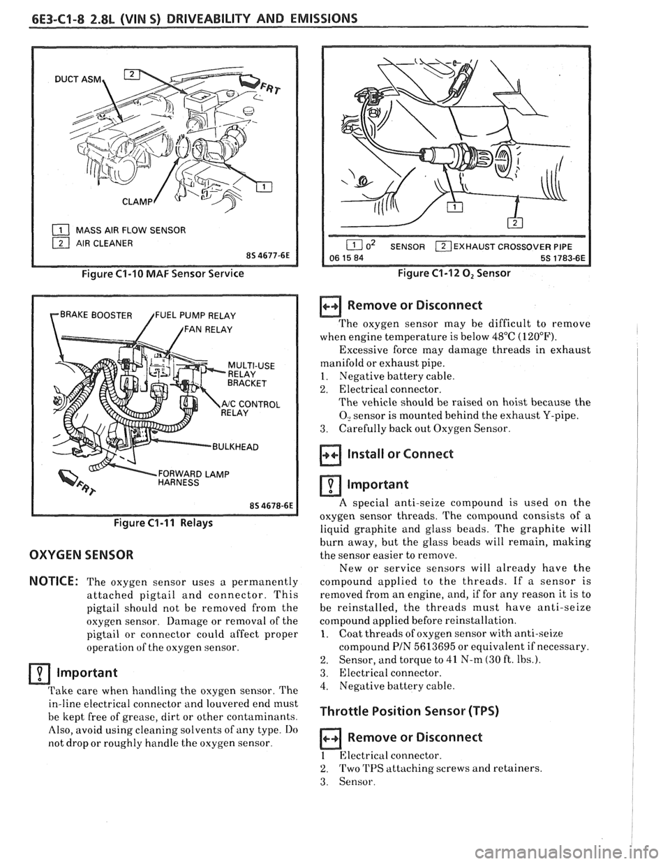
( MASS AIR FLOW SENSOR
Figure C1-10 MAF Sensor Service
BRAKE BOOSTER FUEL PUMP RELAY
/ /FAN RELAY
FORWARD LAMP
/ BULKHEAD
Figure C1-I I Relays
OXYGEN SENSOR
NOTICE:
The oxygen sensor uses a permanently
attached pigtail and connector. This
pigtail should not be removed from the
oxygen sensor. Damage or removal of the
pigtail or connector could affect proper
operation of the oxygen sensor.
Important
Take care when handling the oxygen sensor. The
in-line electrical connector and louvered end must
be kept free of grease, dirt or other contaminants.
Also, avoid using cleaning solvents of any type.
Do
not drop or roughly handle the oxygen sensor.
EXHAUST CROSSOVER PIPE
Figure C1-12 0, Sensor
Remove or Disconnect
The oxygen sensor may be difficult to remove
when engine temperature is below 48°C (120°F).
Excessive force may damage threads in exhaust
manifold or exhaust pipe.
~
1. Negative battery cable.
2. Electrical connector.
The vehicle should be raised on hoist because the
0, sensor is mounted behind the exhaust Y-pipe.
3. Carefully
back out Oxygen Sensor.
Install or Connect 1 i
Important I I
A special anti-seize compound is used on the
oxygen sensor threads. The compound consists
of a
liquid graphite and glass beads. The graphite will
burn away, but the glass beads will remain, making
the sensor easier to remove.
New or service sensors will already have the
compound applied to the threads. If a sensor is
removed from an engine, and, if for any reason it is to
be reinstalled, the threads must have anti-seize
compound applied before reinstallation.
1. Coat threads of oxygen sensor with anti-seize
compound
PIN 5613695 or equivalent if necessary.
2. Sensor, and torque to 41 N-m (30 ft. Ibs.).
3. Electrical connector.
4. Negative battery cable.
Throttle Position Sensor (TPS)
a Remove or Disconnect
1 Electrical connector.
2. Two 'I'PS attaching screws and retainers.
3. Sensor.
Page 786 of 1825
DRIVEABILITY AND EMlSSlONS 2.8L (VIN %I 6E3-C8-1
TRANSMISSION CONVERTER CLUTCH (KC) SYSTEM
AND MANUAL
TRANSMISSION SHIFT LIGHT
CONTENTS
GENERAL DESCRIPTION ................ C8-1 DIAGNOSIS ..........ee...ee....e.e. C8-1
PURPOSE ......................... C8-1 SHIFT LIGHT (MIT) DESCRIPTION ........ C8-1
OPERATION ....................... C8-1 DIAGNOSIS ....................... .. C8-1
ON-CAR SERVICE ...................*. C8-1
GENERAL DESCRIPTION
PURPOSE
The transmission converter clutch (TCC) svstem
uses a solenoid operated valve in the automatic
transmission to couple the engine flywheel to the
output shaft of the transmission thru the torque
converter. This reduces the slippage losses in the
converter, which increases fuel economy.
OPERATION
For the converter clutch to apply, two conditions
must be met:
o Internal transmission fluid pressure must be
correct. For information on internal transmission
operation, see Section
"7A". This section will cover
only the electrical operation of the TCC system.
@ The ECM grounds a switch internally to turn on a
solenoid in the transmission. This moves a check
ball, which will allow the converter clutch to
apply, if the hydraulic pressure is correct, as
described above.
The ECM controls the TCC apply solenoid by
looking at several sensors:
@ Speedo Buffer Sensor (also called vehicle speed
sensor
(VSS). Speed must be above a certain value
before the clutch can apply.
@ Coolant Temperature Sensor. Engine must be
warmed up before clutch can apply about
65OC
(149°F').
Throttle position sensor ('I'PS). After the
converter clutch applies, the
HCM uses the
information from the TPS to release thc clutch
when the car is accelerating or decelerating at a
certain rate.
@ 'I'he brake switch is also part of the 'I'CC circuit as
it will remove battery voltage to the 'KC solenoid
when the brake pedal is depressed.
@ Gear Select Switch. The 4th gear switch is used to
send a signal to the
ECM telling it when the
transmission is in 4th gear. The ECM uses this
information to vary the conditions under which
the clutch applies or releases.
IIowever, the
transmission does not have to be in fourth gear in
order for the ECM to turn the clutch on.
If the converter clutch is applied at all times. the
engine will stall immediately, just as in
u manual
transmission with the clutch applied.
If the converter clutch does not apply, fuel
ecomony
may be lower than expected. If the vehicle
speed sensor fails, the TCC will not apply. If the 4th
gear switch does not operate, the TCC may not apply
at the right time.
DIAGNOSIS
The diagnosis of the TCC system is covered in
CHART C-8
. If the ECM detects a problem in the
system,
a Code 24 should set. In this case see Code 24
CHART.
SHIFT LIGHT (MiT) DESCRIPTION
'The purpose of the shift light is to provide a
display which indicates the optimum fuel economy
point for up
shifling the manual transmission based
on engine speed
and load. 'I'he display is a lamp on the
instrument panel. Activation of the ECM driver turns
the lamp
on.
'I'he shift light circuit can he checlted using
CHAR?' C-8C.
ON-CAR SERVICE
@ See Section "8B" if the shift light bulb needs
replacement.
@ See Section "6E" to repair wiring problem.
@ See Section "6C" if ECM is to be replaced.