PONTIAC FIERO 1988 Service Repair Manual
Manufacturer: PONTIAC, Model Year: 1988, Model line: FIERO, Model: PONTIAC FIERO 1988Pages: 1825, PDF Size: 99.44 MB
Page 1061 of 1825
700-R4-10 AUTOMATIC TRANSMISSION
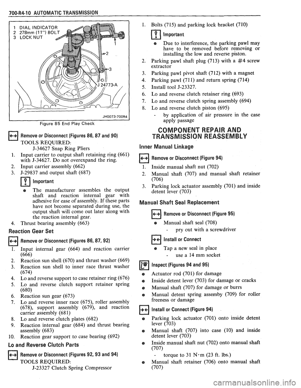
1 DIAL INDICATOR
2
278rnm (1 1") BOLT
3 LOCKNUT
Figure 85 End Play Check
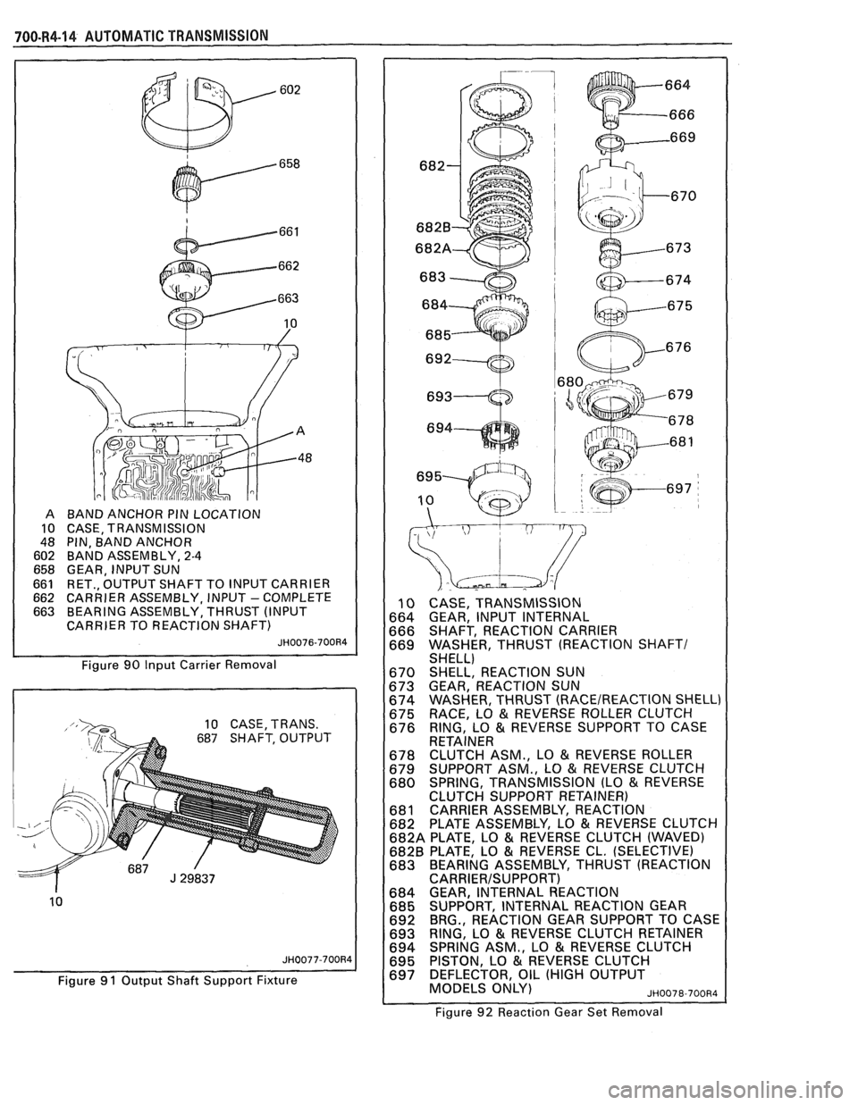
Remove or Disconnect (Figures 86,87 and 90)
TOOLS REQUIRED:
J-34627 Snap Ring Pliers
1. Input
carrier to output shaft retaining ring (661)
with
5-34627. Do not overexpand the ring.
2. Input carrier assembly (662)
3. J-29837
and output shaft (687)
lmportant
a The manufacturer assembles the output
shaft and reaction internal gear with
adhesive for ease of assembly. If these parts
have not become separated during use, the
output shaft will come out later along with
the reaction internal gear.
4. Thrust bearing assembly (663)
Reaction Gear Set
Remove or Disconnect (Figures 86.87.92)
1. Input internal gear (664) and reaction carrier
(666)
2. Reaction
sun shell (670) and thrust washer (669)
3. Reaction
sun shell to inner race thrust washer
(674)
4. Lo and reverse support to case retainer ring (676)
5. Lo and reverse clutch support retainer spring
(680)
6. Reaction sun gear (673)
7. Lo and reverse inner race
(675), roller assembly
(678), support assembly (679), and reaction
carrier assembly (68 1)
8. Lo and reverse clutch plates (682)
9. Reaction internal
gear (684) and thrust bearing
assembly (683)
10. Reaction
gear support to case bearing (692)
Lo and Reverse Clutch Parts
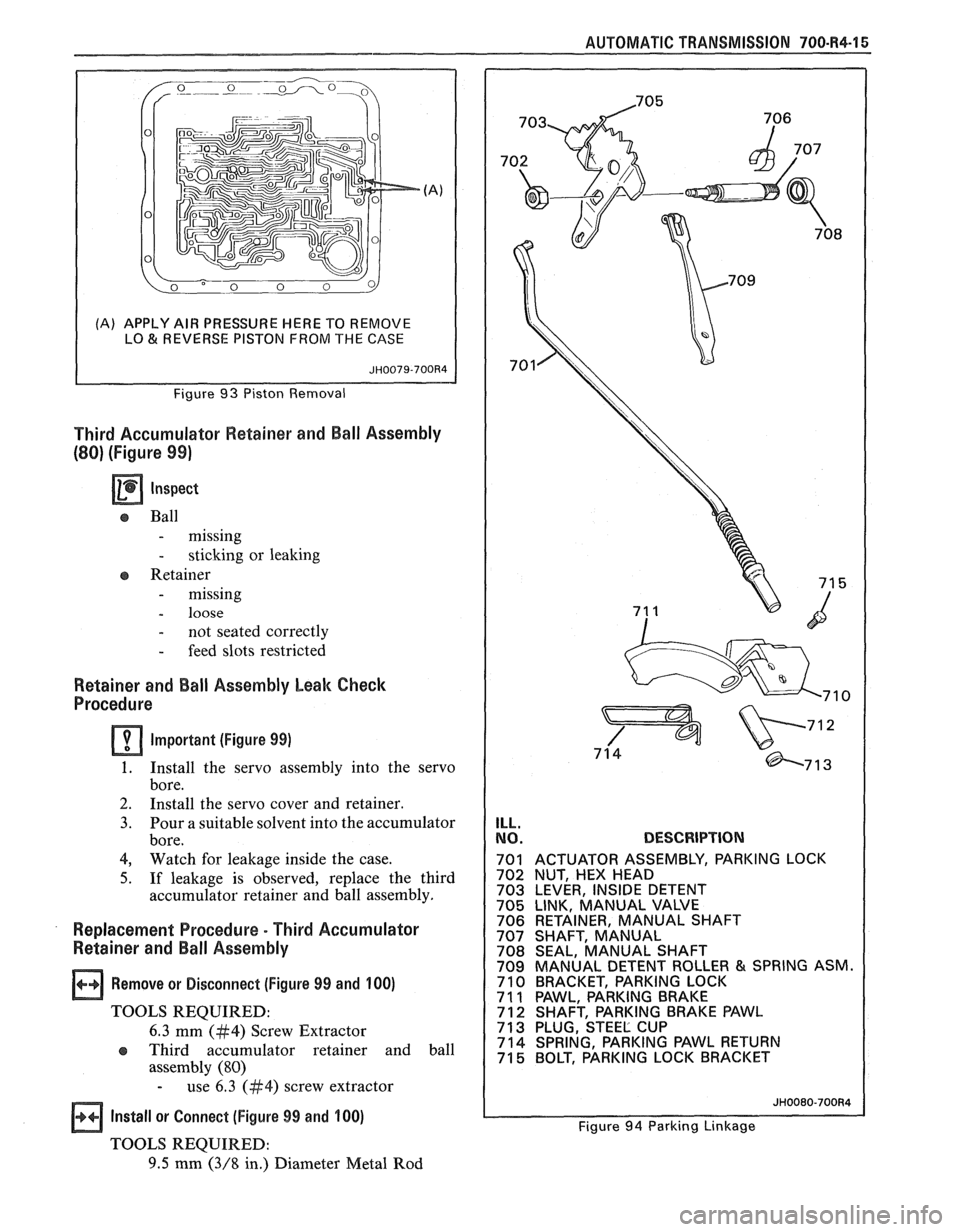
Remove or Disconnect (Figures 92,93 and 94)
TOOLS REQUIRED:
J-23327 Clutch Spring Compressor 1.
Bolts (715) and parking lock bracket (710)
Important
r Due to interference, the parking pawl may
have to be removed before removing or
installing the low and reverse piston.
2. Parking pawl shaft plug (713) with a
#4 screw
extractor
3. Parking pawl pivot shaft (712) with a magnet
4. Parking pawl (71 1) and return spring (714)
5. Install tool J-23327.
6. Lo
and reverse clutch retainer ring (693)
7. Lo
and reverse clutch spring assembly (694)
8. Lo and reverse clutch piston (695)
- by application of air pressure in the case
apply passage
COMPONENT REPAIR AND
TRANSMISSION REASSEMBLY
Inner Manual Linkage
Remove or Disconnect (Figure 94)
1. Inside manual shaft nut (702)
2. Manual shaft
(707) and manual shaft retainer
(706)
3. Parking
lock actuator assembly (701) and inside
detent lever (703)
Manual Shaft Seal Replacement
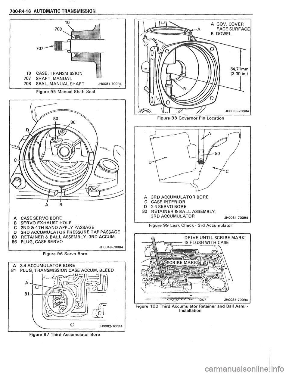
Remove or Disconnect (Figure 95)
a Manual shaft seal (708)
- pry out with a screwdriver
Install or Connect
Tap a new seal in place
- use a 14 mm socket
Inspect (Figures 94 and 95)
a Actuator rod (701) for damage
a Inside detent lever (703) for damage or cracks
e Manual shaft (707) for damage or burrs
Manual detent spring
assemby (709) for roller
freeness or damage
lnstall or Connect (Figure 94)
a Parking lock actuator (701) onto inside detent
lever (703)
a Manual shaft (707) into case (10) and inside
detent lever (703)
a Inside manual shaft nut (702) onto manual shaft
(707)
- torque to 31 N-m (23 ft. lbs.)
r Manual shaft retainer (706) onto manual shaft
(707)
Page 1062 of 1825
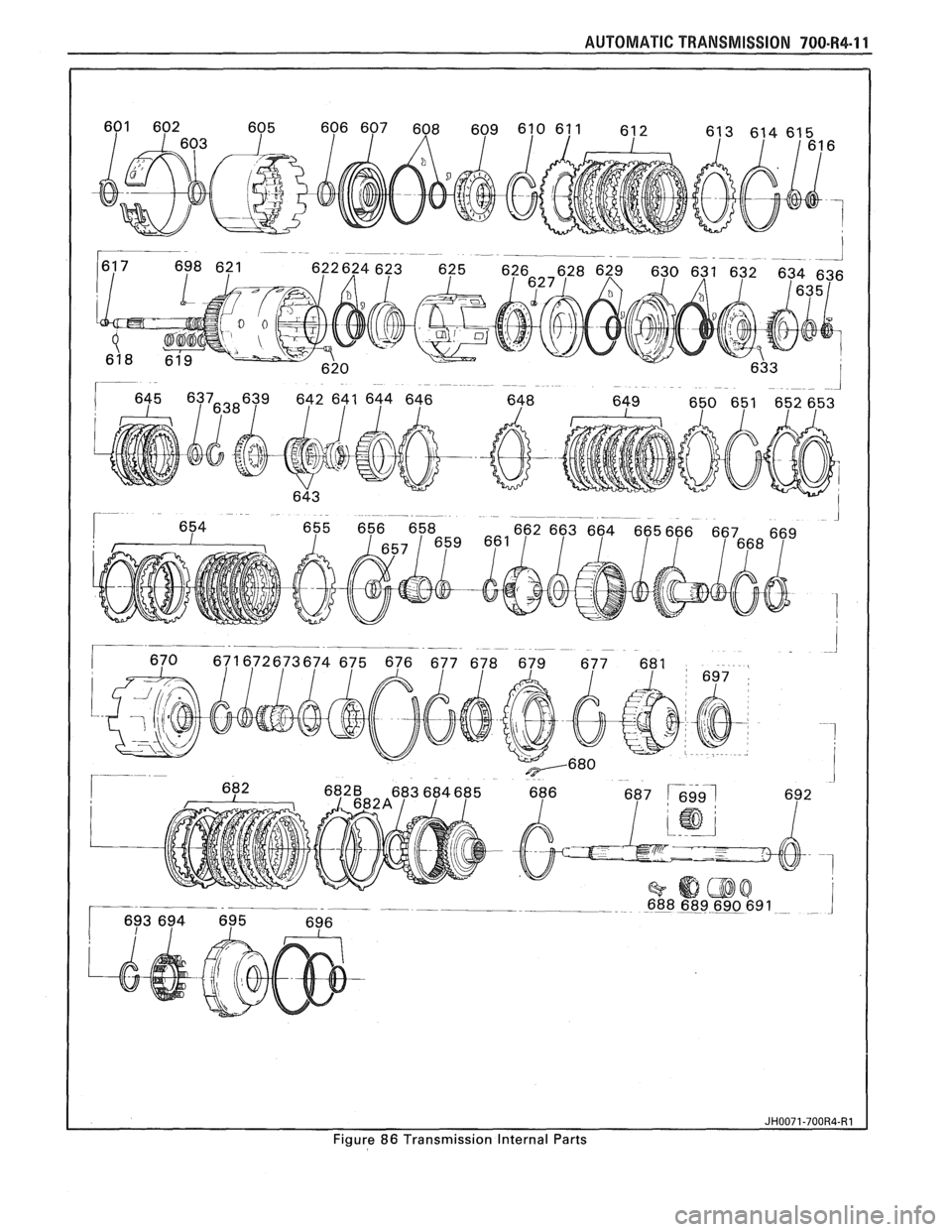
Figure 86 Transmission Internal Parts
Page 1063 of 1825
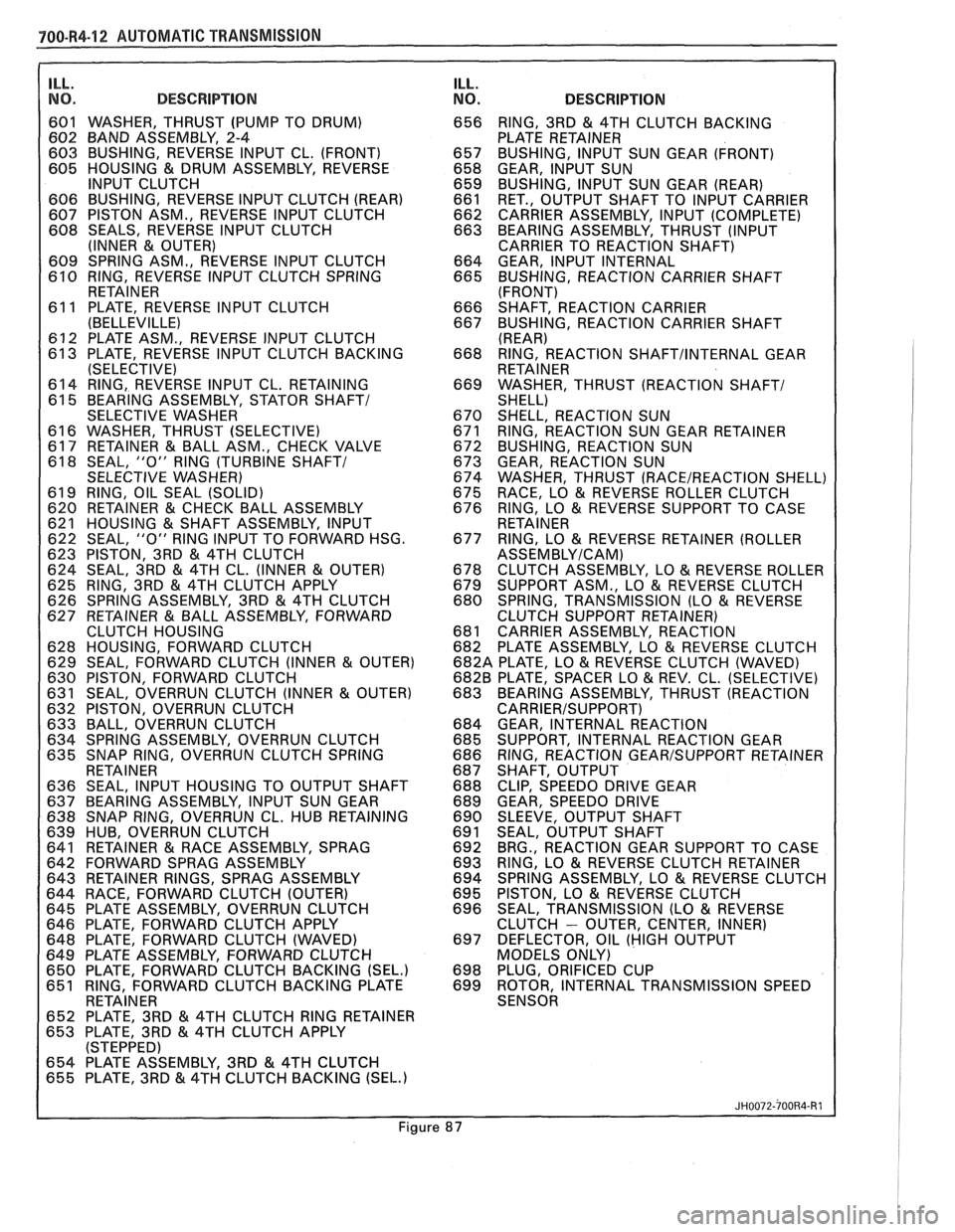
700-R4-12 AUTOMATIC TRANSMISSION
ILL.
I NO. DESCRIPTION
601 WASHER, THRUST (PUMP TO DRUM)
602 BAND ASSEMBLY, 2-4
603 BUSHING, REVERSE INPUT CL. (FRONT)
605 HOUSING
& DRUM ASSEMBLY, REVERSE
INPUT CLUTCH
606 BUSHING, REVERSE INPUT CLUTCH (REAR)
607 PISTON ASM., REVERSE INPUT CLUTCH
608 SEALS, REVERSE INPUT CLUTCH
(INNER
& OUTER)
609 SPRING ASM., REVERSE INPUT CLUTCH
610 RING, REVERSE INPUT CLUTCH SPRING
RETAINER
61 1 PLATE. REVERSE INPUT CLUTCH
(BELLEVILLEI
612 PLATE ASM., REVERSE INPUT CLUTCH
613 PLATE, REVERSE INPUT CLUTCH BACKING
(SELECTIVE)
614 RING, REVERSE INPUT CL. RETAINING
61 5 BEARING ASSEMBLY, STATOR
SHAFT1
SELECTIVE WASHER
61 6 WASHER, THRUST (SELECTIVE)
617 RETAINER
& BALL ASM., CHECK VALVE
61 8 SEAL, "0" RlNG (TURBINE SHAFT/
SELECTIVE WASHER)
61 9 RING, OIL SEAL (SOLID)
620 RETAINER
& CHECK BALL ASSEMBLY
621 HOUSING & SHAFT ASSEMBLY, INPUT
622 SEAL, "0" RlNG INPUT TO FORWARD HSG.
623 PISTON, 3RD
& 4TH CLUTCH
624 SEAL, 3RD & 4TH CL. (INNER & OUTER)
625 RING, 3RD
& 4TH CLUTCH APPLY
626 SPRING ASSEMBLY, 3RD & 4TH CLUTCH
627 RETAINER & BALL ASSEMBLY, FORWARD
CLUTCH HOUSING
628 HOUSING, FORWARD CLUTCH
629 SEAL, FORWARD CLUTCH (INNER
& OUTER)
630 PISTON, FORWARD CLUTCH
631 SEAL, OVERRUN CLUTCH (INNER
& OUTER)
632 PISTON, OVERRUN CLUTCH
633 BALL, OVERRUN CLUTCH
634 SPRING ASSEMBLY, OVERRUN CLUTCH
635 SNAP RING, OVERRUN CLUTCH SPRING
RETAINER
636 SEAL, INPUT HOUSING TO OUTPUT SHAFT
637 BEARING ASSEMBLY, INPUT SUN GEAR
638 SNAP RING, OVERRUN CL. HUB RETAINING
639 HUB, OVERRUN CLUTCH
641 RETAINER
& RACE ASSEMBLY, SPRAG
642 FORWARD SPRAG ASSEMBLY
643 RETAINER RINGS, SPRAG ASSEMBLY
644 RACE, FORWARD CLUTCH (OUTER)
645 PLATE ASSEMBLY, OVERRUN CLUTCH
646 PLATE, FORWARD CLUTCH APPLY
648 PLATE, FORWARD CLUTCH (WAVED)
649 PLATE ASSEMBLY, FORWARD CLUTCH
650 PLATE. FORWARD CLUTCH BACKING
(SEL.) 651 RING, FORWARD CLUTCH BACKING PLATE I RETAINER
I
. . - . . . . . . - . .
652 PLATE, 3RD & 4TH CLUTCH RlNG RETAINER
653 PLATE, 3RD & 4TH CLUTCH APPLY
(STEPPED)
654 PLATE ASSEMBLY, 3RD
& 4TH CLUTCH
655 PLATE, 3RD & 4TH CLUTCH BACKING (SEL.)
ILL.
NO. DESCRIPTION
656 RING, 3RD & 4TH CLUTCH BACKING
PLATE RETAINER
657 BUSHING, INPUT SUN GEAR (FRONT)
658 GEAR, INPUT SUN
659 BUSHING, INPUT SUN GEAR (REAR)
661 RET., OUTPUT SHAFT TO INPUT CARRIER
662 CARRIER ASSEMBLY, INPUT (COMPLETE)
663 BEARING ASSEMBLY, THRUST (INPUT
CARRIER TO REACTION SHAFT)
664 GEAR, INPUT INTERNAL
665 BUSHING, REACTION CARRIER SHAFT
(FRONT)
666 SHAFT, REACTION CARRIER
667 BUSHING, REACTION CARRIER SHAFT
(REAR)
668 RING, REACTION
SHAFTIINTERNAL GEAR
RETAINER
669 WASHER, THRUST (REACTION
SHAFT1 SHELL)
670 SHELL, REACTION SUN
671 RING, REACTION SUN GEAR RETAINER
672 BUSHING, REACTION SUN
673 GEAR, REACTION SUN
674 WASHER, THRUST
(RACE/REACTION SHELL)
675 RACE, LO & REVERSE ROLLER CLUTCH
676 RING, LO & REVERSE SUPPORT TO CASE
RETAINER
677 RING, LO
& REVERSE RETAINER (ROLLER
ASSEMBLYICAM)
678 CLUTCH ASSEMBLY, LO & REVERSE ROLLER
679 SUPPORT ASM., LO & REVERSE CLUTCH
680 SPRING, TRANSMISSION (LO & REVERSE
CLUTCH SUPPORT RETAINER)
681 CARRIER ASSEMBLY, REACTION
682 PLATE ASSEMBLY, LO
& REVERSE CLUTCH
682A PLATE, LO & REVERSE CLUTCH (WAVED)
682B PLATE, SPACER LO
& REV. CL. (SELECTIVE)
683 BEARING ASSEMBLY, THRUST (REACTION
CARRIERISUPPORT)
684 GEAR, INTERNAL REACTION
685 SUPPORT, INTERNAL REACTION GEAR
686 RING, REACTION
GEARISUPPORT RETAINER
687 SHAFT, OUTPUT
688 CLIP, SPEEDO DRIVE GEAR
689 GEAR, SPEEDO DRIVE
690 SLEEVE, OUTPUT SHAFT
691 SEAL, OUTPUT SHAFT
692 BRG., REACTION GEAR SUPPORT TO CASE
693 RING, LO
& REVERSE CLUTCH RETAINER
694 SPRING ASSEMBLY, LO & REVERSE CLUTCH
695 PISTON,
LO & REVERSE CLUTCH
696 SEAL,
TRANSMISSION (LO & REVERSE
CLUTCH - OUTER, CENTER, INNER)
697 DEFLECTOR, OIL (HIGH OUTPUT
MODELS ONLY)
698 PLUG.
ORIFICED CUP
699 ROTOR, INTERNAL TRANSMISSION SPEED
SENSOR
Figure
Page 1064 of 1825
AUTOMAnIC TRANSMISSION 700-R4-13
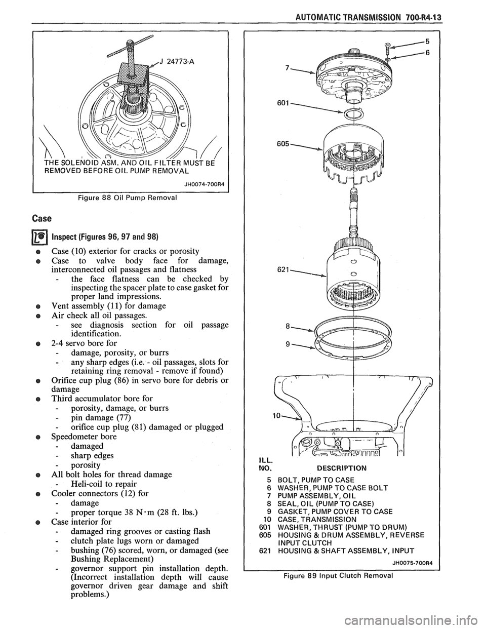
I REMOVED BEFORE OIL PUMP REMOVAL I
Figure 88 Oil Pump Removal
Case
Inspect (Figures 96.97 and 98)
Case (10) exterior for cracks or porosity
Case to valve body face for damage,
interconnected oil passages and flatness
- the face flatness can be checked by
inspecting the spacer plate to case gasket for
proper land impressions.
Vent assembly (1
1) for damage
Air check all oil passages.
- see diagnosis section for oil passage
identification.
2-4 servo bore for
- damage, porosity, or burrs - any sharp edges (i.e. - oil passages, slots for
retaining ring removal
- remove if found)
Orifice cup plug (86) in servo bore for debris or
damage
Third accumulator bore for
- porosity, damage, or burrs
- pin damage (77) - orifice cup plug (81) damaged or plugged
Speedometer bore
- damaged
- sharp edges
- porosity
All bolt holes for thread damage
- Heli-coil to repair
Cooler connectors
(12) for
- damage - proper torque 38 N.m (28 ft. lbs.)
Case interior for
- damaged ring grooves or casting flash - clutch plate lugs worn or damaged
- bushing (76) scored, worn, or damaged (see
Bushing Replacement)
- governor support pin installation depth.
(Incorrect
installation depth will cause
governor driven gear
clamage and shift
problems.)
NO. DESCRIPTION
5 BOLT, PUMP TO CASE
6 WASHER, PUMP TO CASE BOLT
7 PUMP ASSEMBLY, OIL
8 SEAL, OIL (PUMP TO CASE)
9 GASKET, PUMP COVER TO CASE
10 CASE, TRANSMISSION
601 WASHER, THRUST (PUMP TO DRUM)
605 HOUSING
& DRUM ASSEMBLY, REVERSE
INPUT CLUTCH
621 HOUSING &SHAFT ASSEMBLY, INPUT
JH0075-700R4
Figure 89 Input Clutch Removal
Page 1065 of 1825
700-R4-14 AUTOMATIC TRANSMISSION
BAND ANCHOR PIN LOCATION
CASE, TRANSMISSION
PIN, BAND ANCHOR
BAND ASSEMBLY,
2-4
GEAR, INPUT SUN
RET., OUTPUT SHAFT TO INPUT CARRIER
CARRIER ASSEMBLY, INPUT
- COMPLETE
BEARING ASSEMBLY, THRUST (INPUT
CARRIER TO REACTION SHAFT)
JH0076-700R4
Figure 90 Input Carrier Removal
10 CASE, TRANS.
687 SHAFT, OUTPUT
10
JH0077-700R4
Figure 91 Output Shaft Support Fixture
10 CASE, TRANSMISSION
664 GEAR, INPUT INTERNAL
666 SHAFT, REACTION CARRIER
669 WASHER, THRUST (REACTION
SHAFT/ SHELL)
670 SHELL, REACTION SUN
673 GEAR, REACTION SUN
674 WASHER, THRUST
(RACEIREACTION SHELL)
675 RACE, LO & REVERSE
ROLLER CLUTCH
676 RING, LO
& REVERSE SUPPORT
TO CASE
RETAINER
678 CLUTCH ASM.,
LO
& REVERSE ROLLER
679 SUPPORT
ASM., LO
& REVERSE CLUTCH
680 SPRING,
TRANSMISSION (LO & REVERSE
CLUTCH SUPPORT RETAINER)
681 CARRIER ASSEMBLY, REACTION
682 PLATE
ASSEMBLY, LO
& REVERSE CLUTCH
682A PLATE, LO
& REVERSE CLUTCH (WAVED)
682B PLATE, LO & REVERSE CL. (SELECTIVE)
683 BEARING ASSEMBLY, THRUST (REACTION
CARRIERISUPPORT) 684 GEAR, INTERNAL REACTION
685 SUPPORT, INTERNAL REACTION GEAR
692 BRG.,
REACTION GEAR SUPPORT TO CASE
693 RING, LO
& REVERSE
CLUTCH RETAINER
694 SPRING
ASM., LO & REVERSE CLUTCH
695 PISTON, LO & REVERSE
CLUTCH
697 DEFLECTOR, OIL (HIGH OUTPUT
MODELS ONLY)
~~0078-700~4
Figure 92 Reaction Gear Set Removal
Page 1066 of 1825
AUTOMATIC TRANSMISSION 700.84-1 5
(A) APPLY AIR PRESSURE WERE TO REMOVE
LO & REVERSE PISTON FROM THE CASE
Third Accumulator Retainer and Ball Assembly
(80) (Figure 99)
Ball
- missing
- sticking or leaking
Retainer
- missing
- loose
- not seated correctly
- feed slots restricted
Retainer and Ball Assembly Leak Check
Procedure
Important (Figure 99)
1. Install the servo assembly into the servo
bore.
2. Install the servo cover and retainer.
3. Pour a suitable solvent into the accumulator
bore.
DESCRIPTION
701 ACTUATOR ASSEMBLY, PARKING LOCK
Replacement Procedure - Third Accumulator 706 RETAINER, MANUAL SHAFT
707 SHAFT, MANUAL Retainer and Ball Assembly 708 SEAL, MANUAL SHAFT 709 MANUAL DETENT ROLLER & SPRING ASM.
1 Remove or Disconnect (Figure 99 and 100) 710 BRACKET, PARKING LOCK 7 1 1 PAWL, PARKING BRAKE TOOLS REQUIRED: 7 12 SHAFT, PARKING BRAKE PAWL
6.3 mm (#4) Screw Extractor 71 3 PLUG, STEEL CUP
assembly (80)
- use 6.3 (#4) screw extractor
1 Install or Connect (Figure 99 and 100) Figure 94 Parking Linkage
TOOLS REQUIRED:
9.5 mm (3/8 in.) Diameter Metal Rod
Page 1067 of 1825
700-R4-16 AUTOMATIC TRANSMISSION
707
10 CASE, TRANSMISSION
707 SHAFT, MANUAL
Figure
95 Manual Shaft Seal
~igu-r; 98 Governor Pin Location 1
A CASE SERVO BORE B SERVO EXHAUST HOLE
C 2ND
& 4TH BAND APPLY PASSAGE
D 3RD ACCUMULATOR PRESSURE TAP PASSAGE
80 RETAINER & BALL. ASSEMBLY, 3RD ACCUM.
86 PLUG, CASE SERVO
JH0049-700R4
Figure 96 Servo Bore
81 PLUG. TRANSMISSION CASE ACCUM. BLEED A
3RDACCUMULATOR BORE
C CASE INTERIOR
D
2-4 SERVO BORE
80 RETAINER & BALL ASSEMBLY,
3RD ACCUMULATOR
JH0084-700R4
Figure 99 Leak Check - 3rd Accumulator
Figure
100 Third Accumulator Retainer and Ball Asm. - Installation
~i~ure97Ttiird Aecumularor Bore
Page 1068 of 1825
AUTOMATIC TRANSMISSION 700-R4-17
A new third accumulator retainer and ball
assembly
oil feed slots in the retainer must line
up with oil passage in the servo bore.
To be certain of correct installation 653 in.) on the 9.5 mm (3/8")
diameter metal rod. Use it to seat the
third accumulator and ball assembly
as shown. When the scribed line is
flush with the case face, installation
depth is correct.
depth, scribe a mark at
42.0 mm (1.
Page 1069 of 1825
700-R4.18 AUTOMATIC TRANSMISSION
Case Assembly
a Clean
o Thoroughly with solvent
a Air dry
- do not wipe with cloth
Lo and Reverse Clutch Assembly
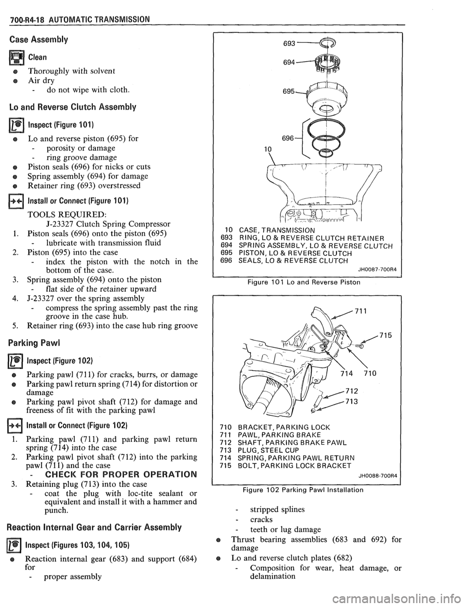
lnspect (Figure 101)
s Lo and reverse piston (695) for
- porosity or damage
- ring groove damage
e Piston seals (696) for nicks or cuts
o Spring assembly (694) for damage
Retainer ring (693) overstressed
Install or Connect (Figure 101)
TOOLS REQUIRED:
J-23327 Clutch Spring Compressor
1. Piston seals (696) onto the piston (695)
- lubricate with transmission fluid
2. Piston (695) into the case
- index the piston with the notch in the
bottom of the case.
3. Spring
assembly (694) onto the piston
- flat side of the retainer upward
4. J-23327 over
the spring assembly
- compress the spring assembly past the ring
groove in the case hub.
5. Retainer ring (693) into the case hub ring groove
Parking Pawl
Inspect (Figure 102)
a Parking pawl (71 1) for cracks, burrs, or damage
o Parking pawl return spring (714) for distortion or
damage
e Parking pawl pivot shaft (712) for damage and
freeness of fit with the parking pawl
Install or Connect (Figure 102)
1. Parking pawl (71 1) and parking pawl return
spring (714) into the case
2. Parking pawl pivot shaft (712) into the parking
pawl (71
1) and the case
- CHECK FOR PROPER OPERATION
3. Retaining plug (713) into the case
- coat the plug with loc-tite sealant or
equivalent and install it with a hammer and
punch.
Reaction Internal Gear and Carrier Assembly
Inspect (Figures 103, 104, 105)
e Reaction internal gear (683) and support (684)
for
- proper assembly
10 CASE, TRANSMISSION
693 RING, LO
& REVERSE CLUTCH RETAINER
694 SPRING ASSEMBLY, LO & REVERSE CLUTCH
695 PISTON, LO & REVERSE CLUTCH
696 SEALS, LO & REVERSE CLUTCH
JH0087-700R4
Figure 101 Lo and Reverse Piston
710 BRACKET, PARKING LOCK
71
1 PAWL, PARKING BRAKE
712 SHAFT, PARKING BRAKE PAWL
713 PLUG, STEEL CUP
714 SPRING, PARKING PAWL RETURN
715 BOLT, PARKING LOCK BRACKET
JH0088-700R4
Figure 102 Parking Pawl Installation
- stripped splines
- cracks
- teeth or lug damage
e Thrust bearing assemblies (683 and 692) for
damage
e Lo and reverse clutch plates (682)
- Composition for wear, heat damage, or
delamination
Page 1070 of 1825
AUTOMATIC TRANSMISSION 700-R4-19
- Steel for heat damage or surface finish
damage
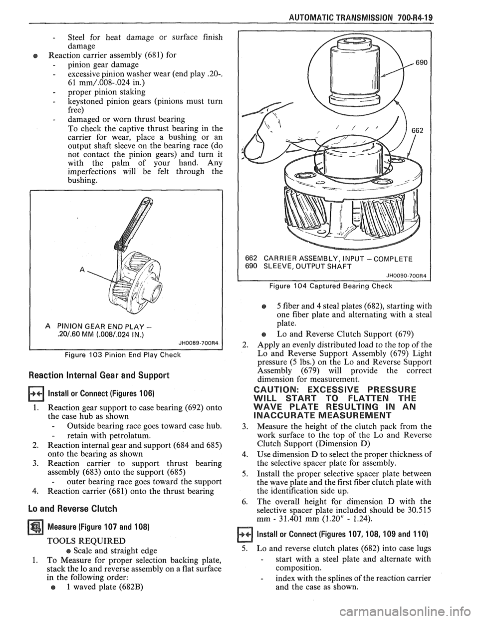
Reaction carrier assembly (681) for
- pinion gear damage
- excessive pinion washer wear (end play -20-.
61 mm/.008-.024 in.)
- proper pinion staking
- keystoned pinion gears (pinions must turn
free)
- damaged or worn thrust bearing
To check the captive thrust bearing in the
carrier for wear, place a bushing or an
output shaft sleeve on the bearing race (do
not contact the pinion gears) and turn it
with the palm of your hand. Any
imperfections will be felt through the
bushing.
A PINION GEAR END PLAY -
.20/.60 MM (.008/.024 IN .)
Figure 103 Pinion End Play Check
Reaction Internal Gear and Support
lnstall or Connect (Figures 106)
1. Reaction gear support to case bearing (692) onto
the case hub as shown
- Outside bearing race goes toward case hub.
- retain with petrolatum.
2. Reaction internal gear and support (684 and 685)
onto the bearing as shown
3. Reaction carrier to support thrust bearing
assembly (683) onto the support (685)
- outer bearing race goes toward the support
4. Reaction carrier (681) onto the thrust bearing
Lo and Reverse Clutch
Measure (Figure 107 and 108)
TOOLS REQUIRED
e Scale and straight edge
1. To Measure for proper selection backing plate,
stack the lo and reverse assembly on a flat surface
in the following order:
o 1 waved plate (682B)
662
CARRIER ASSEMBLY, I NPU'T - COMPLETE
690 SLEEVE, OUTPUT SHAFT
JH0090-700R4
Figure 104 Captured Bearing Check
5 fiber and 4 steal plates (682), starting with
one fiber plate and alternating with a steal
plate.
Lo and Reverse Clutch Support (679)
2. Apply an evenly distributed load to the top of the
Lo and Reverse Support Assembly (679) Light
pressure (5 lbs.) on the Lo and Reverse Support
Assembly (679) will provide the correct
dimension for measurement.
CAUTION: EXCESSIVE PRESSURE
WILL START TO FLATTEN THE
WAVE PLATE RESULTING IN AN
INACCURATE MEASUREMENT
3. Measure
the height of the clutch pack from the
work surface to the top of the Lo and Reverse
Clutch Support (Dimension D)
4. Use dimension D to select the proper thickness of
the selective spacer plate for assembly.
5. Install the proper selective spacer plate between
the wave plate and the first fiber clutch plate with
the identification side up.
6. The
overall height for dimension D with the
selective spacer plate included should be 30.515
mm
- 31.401 mm (1.20" - 1.24).
Install or Connect (Figures 107, 108, 109 and 110)
5. Lo and reverse clutch plates (682) into case lugs
- start with a steel plate and alternate with
composition.
- index with the splines of the reaction carrier
and the case as shown.