PONTIAC FIERO 1988 Service Repair Manual
Manufacturer: PONTIAC, Model Year: 1988, Model line: FIERO, Model: PONTIAC FIERO 1988Pages: 1825, PDF Size: 99.44 MB
Page 1091 of 1825
700-W4-40 AUTOMATIC TRANSMISSION
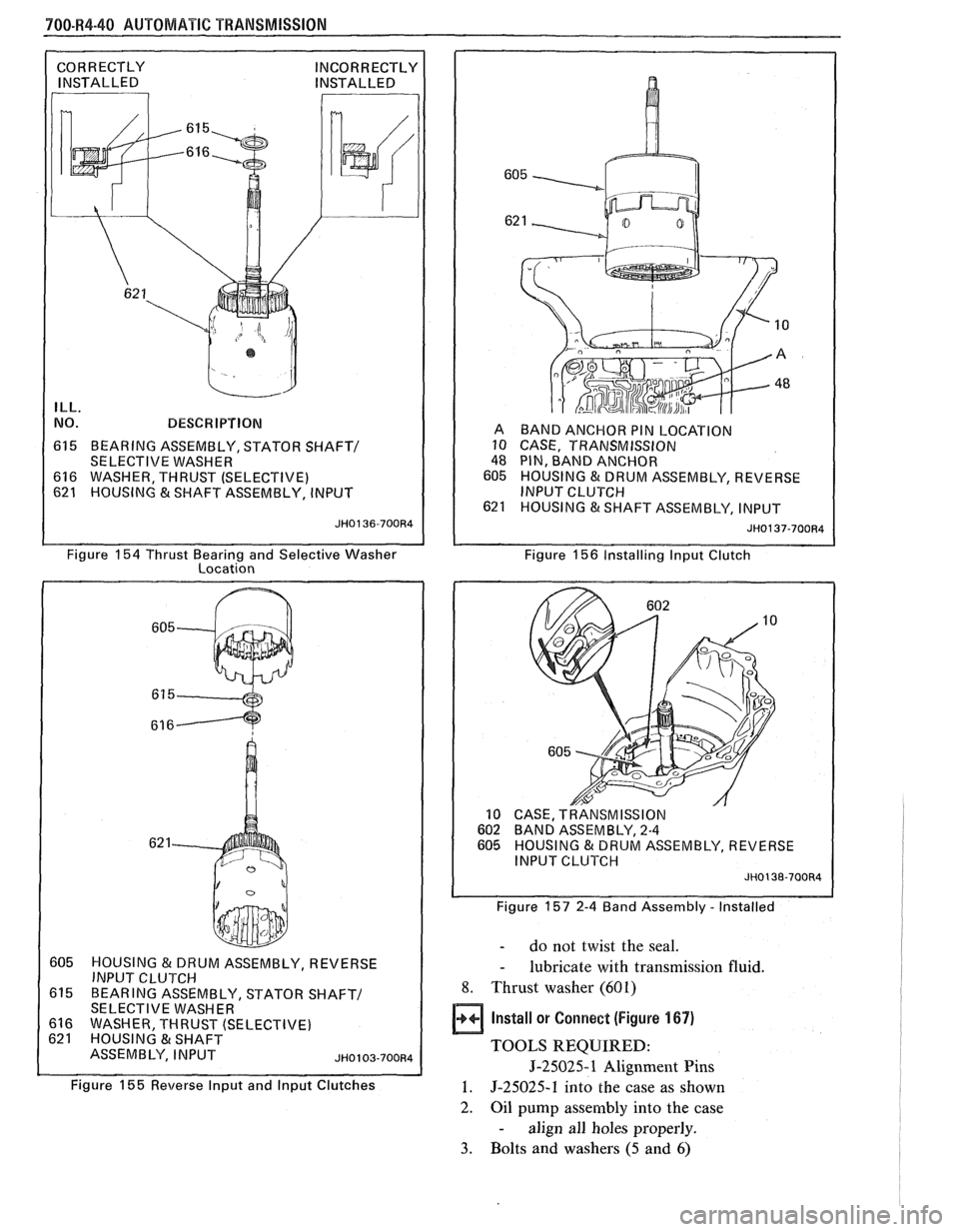
ILL.
NO. BESCW IPTIBN
615 BEARING ASSEMBLY, STATOR SHAFT/
SELECTIVE WASHER
616 WASHER, THRUST (SELECTIVE)
621 HOUSING & SHAFT ASSEMBLY, INPUT A
BAND ANCHOR PIN LOCATION
10 CASE, TRANSMISSION
48 PIN, BAND ANCHOR
605 HOUSING & DRUM ASSEMBLY, REVERSE
INPUT CLUTCH
621 HOUSING &SHAFT ASSEMBLY, INPUT
JH0137-700R4
Figure 154 Thrust Bearing and Selective Washer
Location Figure 156 Installirlg lnput
Clutch
605 HOUSING & DRUM ASSEMBLY, REVERSE I INPUT Cl-VTCH I
615 BEARING ASSEMBLY, STATOR SHAFT/ 1 SELECTIVE WASHER
616 WASHER THRUST (SELECTIVE)
Figure
155 Reverse lnput and lnput Clutches
CASE, TRANSMISSION BAND ASSEMBLY, 2-4
HOUSING & DRUM ASSEMBLY, REVERSE
I
INPUT CLUTCH JH0138-700R4 I
Figure 157 2-4 Band Assembly - Installed
- do not twist the seal.
- lubricate with transmission fluid.
8. Thrust washer (601)
Install or Connect (Figure 167)
TOOLS REQUIRED:
5-25025-1 Alignment Pins
1. 5-25025-1 into the case as shown
2.
Oil pump assembly into the case
- align all holes properly.
3. Bolts and washers (5 and 6)
Page 1092 of 1825
AUTQMATIC TRANSMISSION 700-R4-41
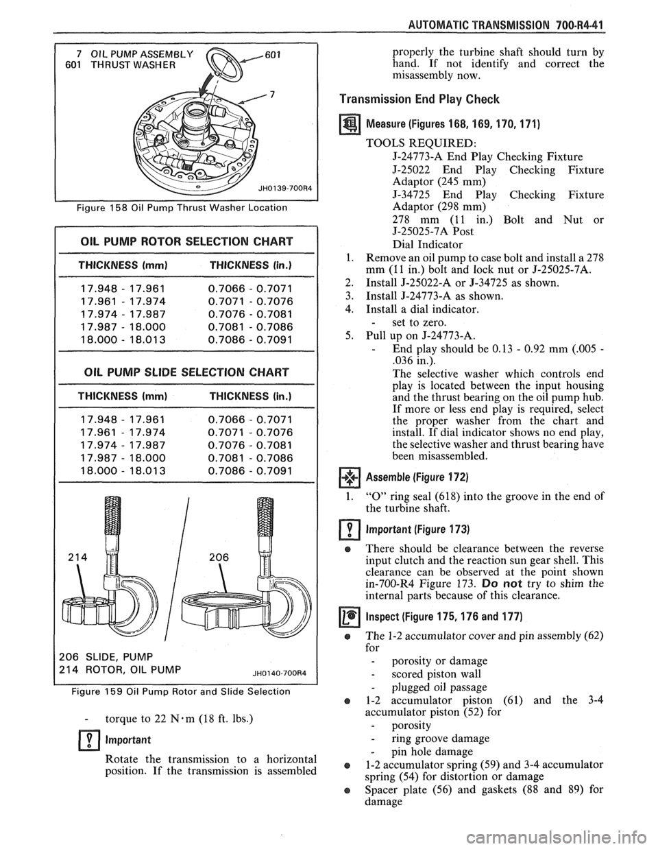
Figure 158 Oil Pump Thrust Washer Location
I OIL PUMP ROTOR SELECTION CHART I
I THICKNESS (mml THICKNESS (in.)
17.948 - 17.961
0.7066 - 0.7071
17.961
- 17.974 0.7071 - 0.7076
17.974
- 17.987 0.7076 - 0.7081
17.987
- 18.000 0.7081 - 0.7086
18.000
- 18.01 3 0.7086 - 0.7091
OIL PUMP SLlDE SELECTION CHART
THICKNESS (mm) THICKNESS (in.)
206 SLIDE, PUMP
214 ROTOR OIL PUMP
Figure 159 Oil Pump Rotor and Slide Selection
- torque to 22 N-m (18 ft. lbs.)
lmportant
Rotate the transmission to a horizontal
position. If the transmission is assembled properly
the turbine shaft should turn by
hand. If not identify and correct the
misassembly now.
Transmission End Play Checlc
a Measure (Figures 168, 169, 170. 171)
TOOLS REQUIRED:
5-24773-A End Play Checking Fixture
J-25022 End Play Checking Fixture
Adaptor (245 mm)
5-34725 End Play Checking Fixture
Adaptor (298 mm)
278 mm (11 in.) Bolt and Nut or
J-25025-7A
Post
Dial Indicator
1. Remove an oil pump to case bolt and install a 278
mm (11 in.) bolt and
lock nut or J-25025-7A.
2. Install 5-25022-A or
5-34725 as shown.
3. Install
J-24773-A as shown.
4. Install a dial indicator.
- set to zero.
5. Pull up on J-24773-A.
- End play should be 0.13 - 0.92 mm (.005 -
,036 in.).
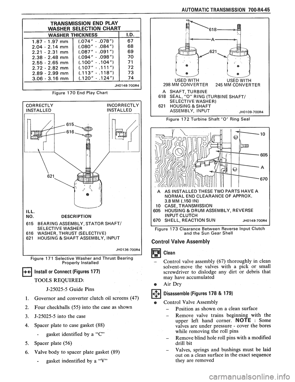
The selective washer which controls end
play is located between the input housing
and the thrust bearing on the oil pump hub.
If more or less end play is required, select
the proper washer from the chart and
install. If dial indicator shows no end play,
the selective washer and thrust bearing have
been misassembled.
Assemble (Figure 172)
1. "0" ring seal (618) into the groove in the end of
the turbine shaft.
lmportant (Figure 173)
e There should be clearance between the reverse
input clutch and the reaction sun gear shell. This
clearance can be observed at the point shown
in-700-R4 Figure 173.
Do not try to shim the
internal parts because of this clearance.
Inspect (Figure 175,176 and 177) -
e The 1-2 accumulator cover and pin assembly (62)
for
- porosity or damage
- scored piston wall
- plugged oil passage
e 1-2 accumulator piston (61) and the 3-4
accumulator piston (52) for
- porosity
- ring groove damage
- pin hole damage
e 1-2 accumulator spring (59) and 3-4 accumulator
spring (54) for distortion or damage
e Spacer plate (56) and gaskets (88 and 89) for
damage
Page 1093 of 1825
700-R4-42 AUTOMATIC TRANSMISSION
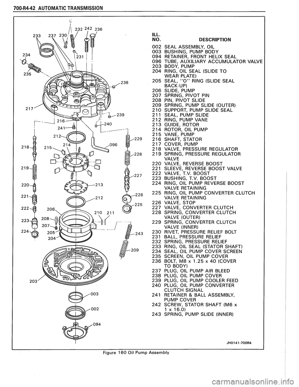
ILL.
NO.
Figure 160 Oil Puml
DESCRIPTION
SEAL ASSEMBLY, OIL
BUSHING, PUMP BODY
RETAINER, FRONT HELIX SEAL
TUBE, AUXILIARY ACCUMULATOR VAI
BODY, PUMP
RING, OIL SEAL (SLIDE TO
WEAR PLATE)
SEAL,
"0" RING (SLIDE SEAL
BACK-UP)
SLIDE, PUMP
SPRING, PIVOT PIN
PIN, PIVOT SLlDE
SPRING, PUMP SLlDE (OUTER)
SUPPORT, PUMP SLlDE SEAL
SEAL, PUMP SLlDE
RING, PUMP VANE
GUIDE, ROTOR
ROTOR, OIL PUMP
VANE, PUMP
SHAFT, STATOR
COVER, PUMP
VALVE, PRESSURE REGULATOR
SPRING, PRESSURE REGULATOR
VALVE
VALVE, REVERSE BOOST
SLEEVE, REVERSE BOOST VALVE
VALVE, T.V. BOOST
BUSHING, T.V. BOOST
RING, OIL PUMP REVERSE BOOST
VALVE RETAINING
RING, OIL PUMP CONVERTER CLUTCH
VALVE RETAINING
VALVE, STOP
VALVE. CONVERTER CLUTCH
SPRING,
CONVERTER CLUTCH
VALVE (OUTER)
SPRING, CONVERTER CLUTCH
VALVE (INNER)
RIVET, PRESSURE RELIEF BOLT
BALL, PRESSURE RELIEF
SPRING, PRESSURE RELIEF
RING, OIL SEAL (STATOR SHAFT)
SEAL, OIL PUMP COVER SCREEN
SCREEN, OIL PUMP COVER
BOLT,
M8 x 1.25 x 40 (COVER
TO BODY)
PLUG, OIL PUMP AIR BLEED
PLUG, OIL PUMP COVER
PLUG, OIL PUMP COOLER FEED
PLUG, OIL PUMP CONVERTER
CLUTCH SIGNAL
RETAINER
& BALL ASSEMBLY,
PUMP COVER
SCREW, STATOR SHAFT (M6
x 1 x 16.0)
SPRING, PUMP SLlDE (INNER)
Page 1094 of 1825
AUTOMATIC TRANSMISSION 700-R4-43
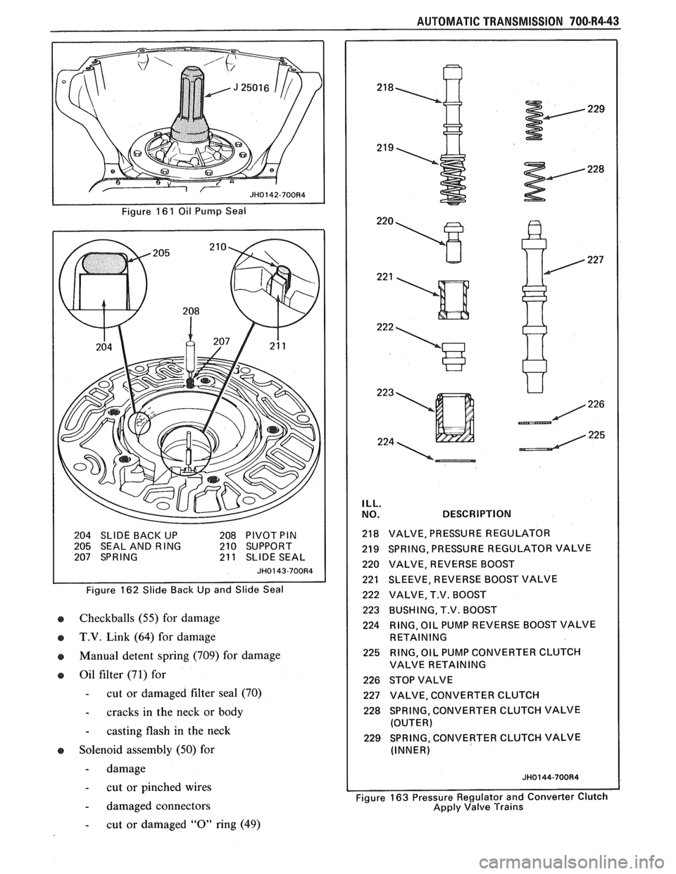
Figure 16 1 Oil Pump Seal
204 SLIDE
BACI< UP 208 PIVOT PIN 205 SEAL AND RING 210 SUPPORT
207 SPRING 21 1 SLIDE SEAL
JH0143-700R4
Figure 162 Slide Back Up and Slide Seal
o Checkballs (55) for damage
IB T.V. Link (64) for damage
IB Manual detent spring (709) for damage
o Oil filter (71) for
- cut or damaged filter seal (70)
- cracks in the neck or body
- casting flash in the neck
IB Solenoid assembly (50) for
- damage
- cut or pinched wires
- damaged connectors
ILL.
NO. DESCRIPTION
218 VALVE, PRESSURE REGULATOR
219 SPRING, PRESSURE REGULATOR VALVE
220 VALVE, REVERSE BOOST
221 SLEEVE, REVERSE BOOST VALVE
222 VALVE, T.V. BOOST
223 BUSHING, T.V. BOOST
224 RING,
OIL PUMP REVERSE BOOST VALVE
RETAINING
225 RING, OIL PUMP CONVERTER CLUTCH
VALVE RETAINING
226 STOP VALVE
227 VALVE, CONVERTER CLUTCH
228 SPRING, CONVERTER CLUTCH VALVE
(OUTER)
229 SPRING, CONVERTER CLUTCH VALVE
(INNER)
I Figure 163 Pressure Regulator and Converter Clutch
Apply Valve Trains
- cut or damaged "0" ring (49)
Page 1095 of 1825
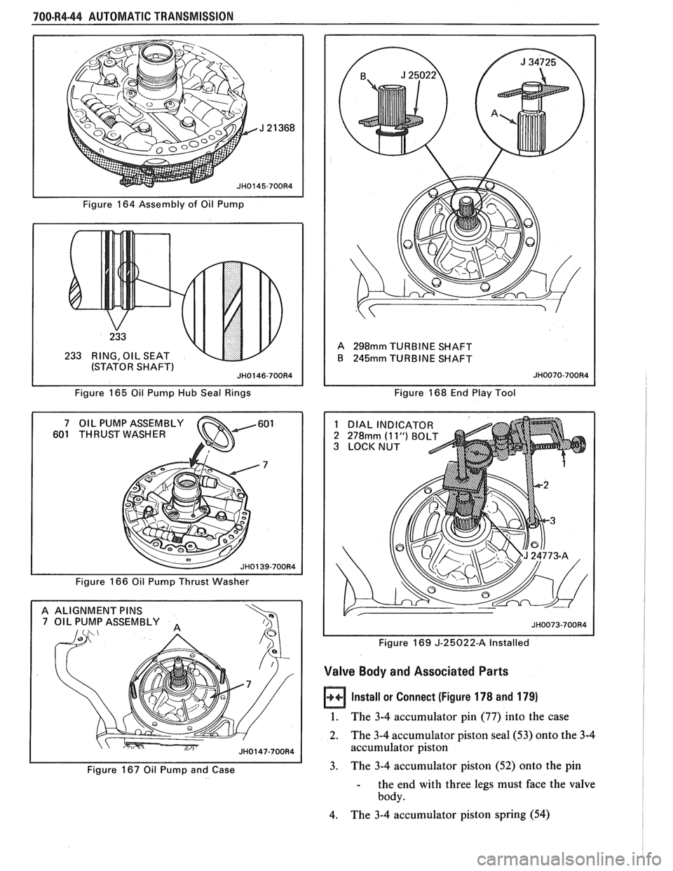
700-R4-44 AUTOMATIC TRANSMISSION
Figure 164 Assembly of Oil Pump
233 RING, OIL SEAT
(STATOR SHAFT
Figure 165 Oil Pump Hub Seal Rings
601 THRUST WASHER
Figure 166 Oil Pump Thrust Washer
A ALIGNMENT
PINS 7 OIL PUMP ASSEMBLY
Figure 167 Oil Pump and Case A
298mm TURBINE
SHAFT
B
245mm TURBINE SHAFT
Figure 168 End Play Tool
1 DIAL INDICATOR
2
278mm (1 1") BO 3 LOCKNUT
Figure 169
J-25022-A Installed
Valve Body and Associated Parts
Install or Connect (Figure 178 and 179)
1. The 3-4 accumulator pin (77) into the case
2. The
3-4 accumulator piston
sea1 (53) onto the 3-4
accumulator piston
3. The 3-4 accumulator piston (52) onto the pin
- the end with three legs must face the valve
body.
4. The 3-4 accumulator piston spring (54)
Page 1096 of 1825
AUTOMATIC TRANSMISSION 700-84-45
TRANSMISSION END PLAY
WASHER SELECTION
CI-IART
6 8
6 9
70
7 1
7 2
73
7 4
JH0148-700R4
Figure 170 End Play Chart
CORRECTLY INSTALLED INCORRECTLY
INSTALLED
,
ILL.
LY
NO. DESCRIPTION
615 BEARING ASSEMBLY, STATOR SHAFT/ SELECTIVE WASHER
616 WASHER, THRUST (SELECTIVE)
621 HOUSING & SHAFT ASSEMBLY, INPUT
Figure
17 1 Selective Washer and Thrust Bearing
Properly Installed
Install or Connect (Figures 177)
TOOLS REQUIRED:
J-25025-5 Guide Pins
1. Governor and converter clutch oil screens (47)
2. Four checkballs (55) into the case as shown
3. J-25025-5 into the case
4. Spacer plate to case gasket (88)
- gasket identified by a "C"
5. Spacer plate (56)
6.
Valve body to spacer plate gasket (89)
- gasket indentified by a "V"
USED WITH USED WITH 298 MM CONVERTER 245 MM CONVERTER
A SHAFT, TURBINE
618 SEAL,"O"RlNG(TURBINESHAFT/
SELECTIVE WASHER) 621 HOUSING & SHAFT
ASSEMBLY, INPUT
JH0109-700R4
Figure 172 Turbine Shaft "0" Ring Seal
A AS INSTALLED THESE TWO PARTS HAVE A
NORMAL END CLEARANCE OF APPROX.
3.8 MM
(.I50 IN) 10 CASE, TRANSMISSION 605 HOUSING & DRUM ASSEMBLY, REVERSE
INPUT CLUTCH
670 SHELL, REACTION SUN ~~0149-700~4
Figure 173 Clearance Between Reverse Input Clutch
and the Sun Gear Shell
Control Valve Assembly
Clean
- Control valve assembly (67) thoroughly in clean
solvent-move the valves with a pick or small
screwdriver to dislodge any dirt
br debris that
may have accumulated
e Air Dry
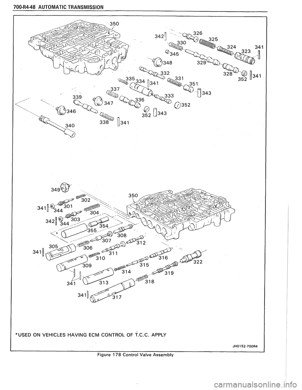
Disassemble (Figures 178 & 179)
e Control Valve Assembly
- Position as shown on a clean surface
- Remove valve trains beginning with the
upper left hand corner.
NOTE : Some
valves are under pressure
- cover the bores
while removing the roll pins
- Remove blind hole roll pins with a modified
drill bit
- Valves, springs and bushings must be laid
out on a clean surface in the exact sequence
they are removed
Page 1097 of 1825
700.R4.46 AUTOMATIC TRANSMISSION
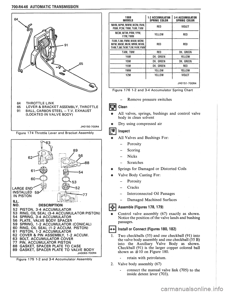
64 THROTTLE LINK
65 LEVER & BRACKET
ASSEMBLY, THROTTLE
91 BALL, CARBON STEEL - T.V. EXHAUST
(LOCATED IN VALVE BODY)
Figure 174 Throttle Lever and Bracket Assembly
h
LARGE END
INSTALLED 59
IN PISTON
I ILL.
NO. DESCRIPTION
52 PISTON, 3-4 ACCUMULATOR
53 RING, OIL SEAL
(3-4 ACCUMULATOR PISTON)
54 SPRING, 3-4 ACCUMULATOR
56 PLATE, VALVE BODY SPACER
59 SPRING,
1-2 ACCUMULATOR (CONICAL) 60 RING, OIL SEAL (1-2 ACCUM. PISTON) 61 PISTON, 1-2 ACCUMULATOR
62 COVER & PIN ASSEMBLY, 1-2 ACCUM. 63 BOLT, ACCUMULATOR COVER 77 PIN, ACCUMULATOR PISTON
88 GASKET, SPACER PLATE TO CASE
89 GASKET, SPACER PLATE TO VALVE BODY
JH0063-700R4
Figure 175 1-2 and 3-4 Accumulator Assembly
PBM, PCM,TNM,TUM,TXM
FAM,FJM, FMM,MAM, MOM, MFM, MKM, MLM,MRM,MXM, 1 RED I RED THM,TJM,TKM,TLM,YKM,YNM
Figure 176 1-2 and 3-4 Accumulator Spring Chart
- Remove pressure switches
Clean
o All valves, springs, bushings and control valve
body in clean solvent
o Dry using compressed air
o All Valves and Bushings For:
- Porosity
- Scoring
- Nicks
- Scratches
e Springs for Damaged or Distorted Coils
e Valve Body Casting For:
- Porosity
- Cracks
- Interconnected Oil Passages
- Damaged Machined Surfaces
Assemble (Figures 178, 179)
e Control valve assembly (67) exactly as shown.
Notice the
positiori of the valve lands and bushing
passages.
Install or Connect (Figures 180, 182)
1. Two checkballs (55) and one checkball (9 1) into
the valve body assembly and one checkball (55
B)
into the Auxiliary Valve Body as shown.
Checkball (91) is the larger copper colored ball
shown as
# 10 on Figure 180.
- retain with petrolatum.
2. Valve body assembly (67)
- connect the manual valve link (705) to the
inside detent lever (703).
Page 1098 of 1825
AUTOMATIC TRANSMISSION 700-R4-47
Auxiliary Accumulator Valve Body Assembly
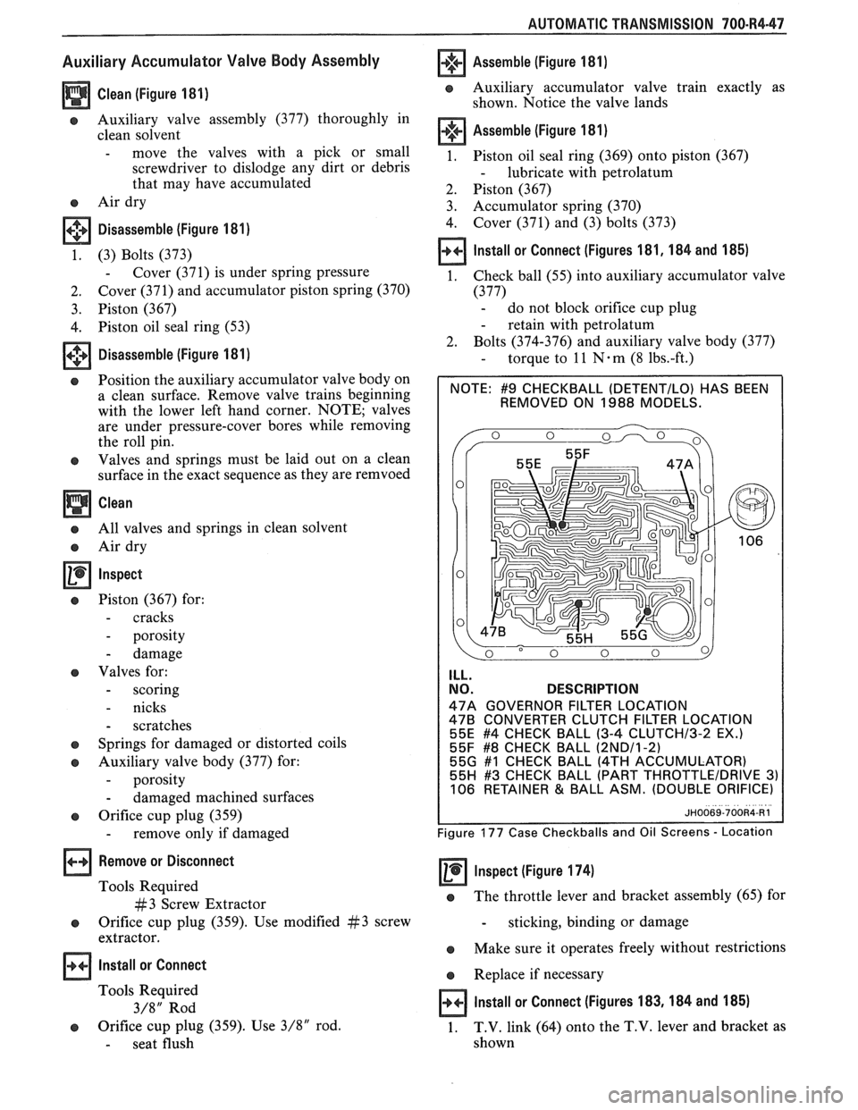
Clean (Figure 181)
e Auxiliary valve assembly (377) thoroughly in
clean solvent
- move the valves with a pick or small
screwdriver to dislodge any dirt or debris
that may have accumulated
e Air dry
+*+ Disassemble (Figure 181) m
1. (3) Bolts (373)
- Cover (371) is under spring pressure
2. Cover (371) and accumulator piston spring (370)
3. Piston (367)
4. Piston oil seal ring (53)
Disassemble (Figure 181)
e Position the auxiliary accumulator valve body on
a clean surface. Remove valve trains beginning
with the lower left hand corner. NOTE; valves
are under pressure-cover bores while removing
the roll pin.
e Valves and springs must be laid out on a clean
surface in the exact sequence as they are remvoed
Clean
a All valves and springs in clean solvent
e Air dry
Inspect
e Piston (367) for:
- cracks
- porosity
- damage
e Valves for:
- scoring
- nicks
- scratches
e Springs for damaged or distorted coils
a Auxiliary valve body (377) for:
- porosity
- damaged machined surfaces
e Orifice cup plug (359)
- remove only if damaged
Remove or Disconnect
Tools Required
#3 Screw Extractor
e Orifice cup plug (359). Use modified #3 screw
extractor.
Install or Connect
Tools Required
3/8" Rod
e Orifice cup plug (359). Use 3/8" rod.
- seat flush
Assemble (Figure 181)
e Auxiliary accumulator valve train exactly as
shown. Notice the valve lands
Assemble (Figure 181)
1. Piston oil seal ring (369) onto piston (367)
- lubricate with petrolatum
2. Piston (367)
3. Accumulator spring (370)
4. Cover
(371) and (3) bolts (373)
Install or Connect (Figures 181,184 and 185)
1. Check ball (55) into auxiliary accumulator valve
(377) - do not block orifice cup plug
- retain with petrolatum
2. Bolts (374-376) and auxiliary valve body (377)
- torque to 11 N-m (8 1bs.-ft.)
(DETENTILO) HAS BEEN
REMOVED ON 1988 MODELS.
ILL.
NO. DESCRIPTION
47A GOVERNOR FILTER LOCATION 478 CONVERTER CLUTCH FILTER LOCATION
55E #4 CHECK BALL (3-4 CLUTCHl3-2 EX.) 55F #8 CHECK BALL (2NDl1-2) 55G #I CHECK BALL (4TH ACCUMULATOR)
55H #3 CHECK BALL (PART THROTTLEIDRIVE 3) 106 RETAINER & BALL ASM. (DOUBLE ORIFICE)
Figure 177 Case Checkballs and Oil Screens - Location
Inspect (Figure 174) -
e The throttle lever and bracket assembly (65) for
- sticking, binding or damage
e Make sure it operates freely without restrictions
e Replace if necessary
Install or Connect (Figures 183,184 and 185)
1. T.V. link
(64) onto the T.V. lever and bracket as
shown
Page 1099 of 1825
Page 1100 of 1825
AUTOMATIC TRANSMISSION 700-R4-49
--
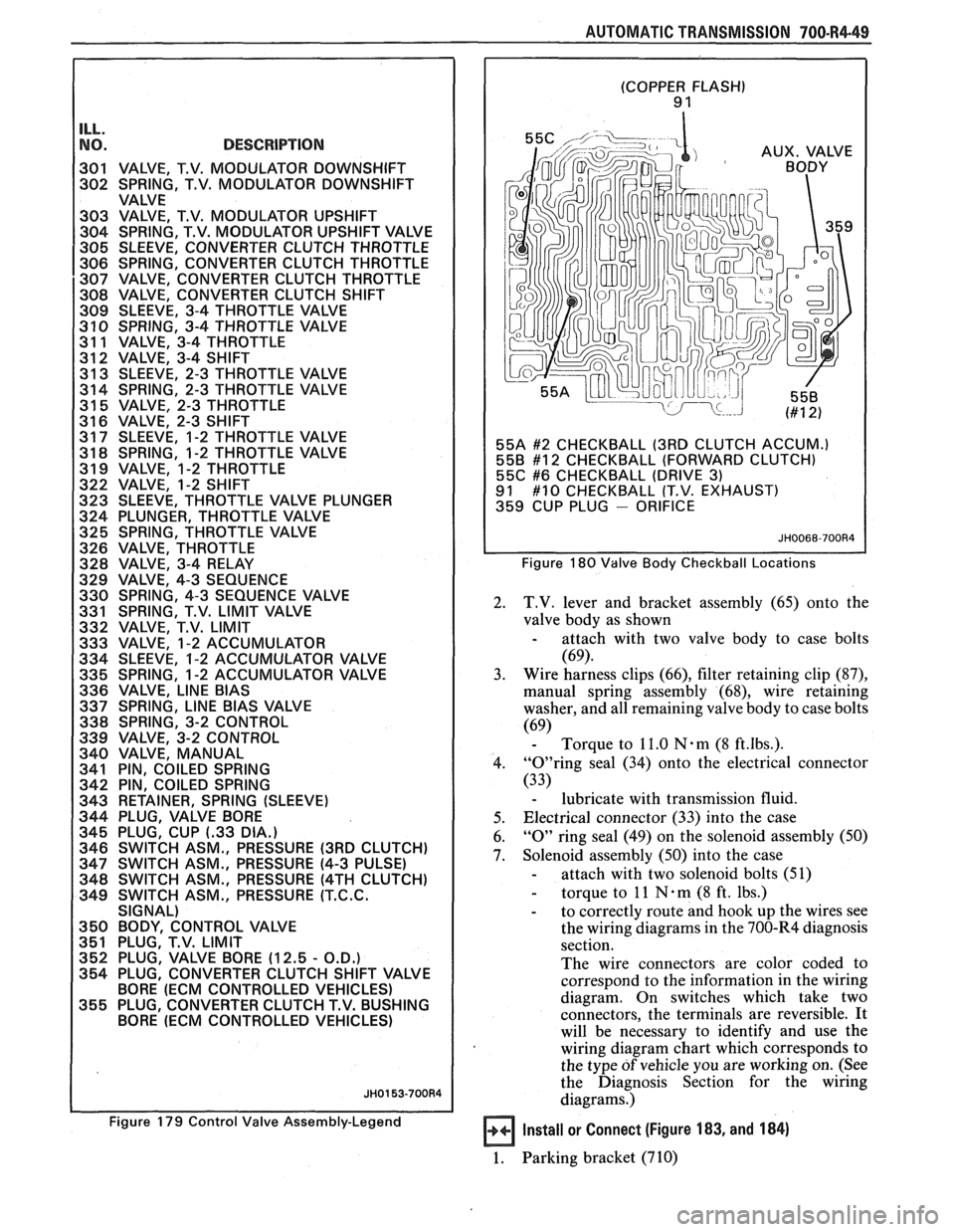
NO. DESCRIPTION I 301 VALVE, T.V. MODULATOR DOWNSHIFT
302 SPRING, T.V. MODULATOR DOWNSHIFT
VALVE
303 VALVE, T.V. MODULATOR UPSHIFT
304 SPRING, T.V. MODULATOR UPSHIFT VALVE
305 SLEEVE, CONVERTER CLUTCH THROTTLE
306 SPRING, CONVERTER CLUTCH THROTTLE
307 VALVE, CONVERTER CLUTCH THROTTLE
308 VALVE, CONVERTER CLUTCH SHlFT
309 SLEEVE, 3-4 THROTTLE VALVE
3 10 SPRING, 3-4 THROTTLE VALVE
31 1 VALVE, 3-4 THROTTLE
312 VALVE, 3-4 SHlFT
31 3 SLEEVE, 2-3 THROTTLE VALVE
314 SPRING, 2-3 THROTTLE VALVE
31
5 VALVE, 2-3 THROTTLE
31 6 VALVE, 2-3 SHlFT
31 7 SLEEVE, 1-2 THROTTLE VALVE
31
8 SPRING, 1-2 THROTTLE VALVE
31 9 VALVE, 1-2 THROTTLE
322 VALVE, 1-2 SHlFT
323 SLEEVE, THROTTLE VALVE PLUNGER
324 PLUNGER, THROTTLE VALVE
325 SPRING, THROTTLE VALVE
326 VALVE, THROTTLE
328 VALVE, 3-4 RELAY
329 VALVE, 4-3 SEQUENCE
330 SPRING, 4-3 SEQUENCE VALVE
331 SPRING, T.V.
LIMIT VALVE
332 VALVE, T.V.
LIMIT
333 VALVE, 1-2 ACCUMULATOR
334 SLEEVE, 1-2 ACCUMULATOR VALVE
335 SPRING, 1-2 ACCUMULATOR VALVE
336 VALVE,
LlNE BlAS
337 SPRING, LlNE BlAS VALVE
338 SPRING, 3-2 CONTROL
339 VALVE, 3-2 CONTROL
340 VALVE, MANUAL
341 PIN, COILED SPRING
342 PIN, COILED SPRING
343 RETAINER, SPRING (SLEEVE)
344 PLUG, VALVE BORE
345 PLUG, CUP
(-33 DIA.)
346 SWITCH ASM., PRESSURE (3RD CLUTCH)
347 SWITCH ASM., PRESSURE (4-3 PULSE)
348 SWITCH ASM., PRESSURE
(4TH CLUTCH)
349 SWITCH ASM., PRESSURE
(T.C.C.
SIGNAL)
350 BODY, CONTROL VALVE
351 PLUG, T.V. LIMIT
352 PLUG, VALVE BORE (12.5
- O.D.)
354 PLUG, CONVERTER CLUTCH SHlFT VALVE
BORE
(ECM CONTROLLED VEHICLES)
355 PLUG, CONVERTER CLUTCH T.V. BUSHING
BORE
(ECM CONTROLLED VEHICLES)
Figure 179 Control Valve Assembly-Legend
(COPPER FLASH) 9 1
55A
#2 CHECKBALL (3RD CLUTCH ACCUM.)
558 #12 CHECKBALL (FORWARD CLUTCH)
55C #6 CHECKBALL (DRIVE 3) 91 #10 CHECKBALL (T.V. EXHAUST)
359 CUP PLUG - ORIFICE
Figure 180 Valve Body Checkball Locations
2. T.V. lever and bracket assembly (65) onto the
valve body as shown
- attach with two valve body to case bolts
(69).
3. Wire harness
clips (66), filter retaining clip (87),
manual spring assembly (68), wire retaining
washer, and all remaining valve body to case bolts
(69) - Torque to 11.0 Nam (8 ft.lbs.).
4. "0"ring seal (34) onto the electrical connector
(33)
- lubricate with transmission fluid.
5. Electrical connector
(33) into the case
6.
"0" ring seal (49) on the solenoid assembly (50)
7. Solenoid assembly (50) into the case
- attach with two solenoid bolts (51)
- torque to 11 N . m (8 ft. lbs.)
- to correctly route and hook up the wires see
the wiring diagrams in the 700-R4 diagnosis
section.
The wire connectors are color coded to
correspond to the information in the wiring
diagram. On switches which take two
connectors, the terminals are reversible.
It
will be necessary to identify and use the
wiring diagram chart which corresponds to
the type
of vehicle you are working on. (See
the Diagnosis Section for the wiring
diagrams.)
Install or Connect (Figure 183, and 184)
1. Parking bracket (710)