PONTIAC FIERO 1988 Service Repair Manual
Manufacturer: PONTIAC, Model Year: 1988, Model line: FIERO, Model: PONTIAC FIERO 1988Pages: 1825, PDF Size: 99.44 MB
Page 1451 of 1825
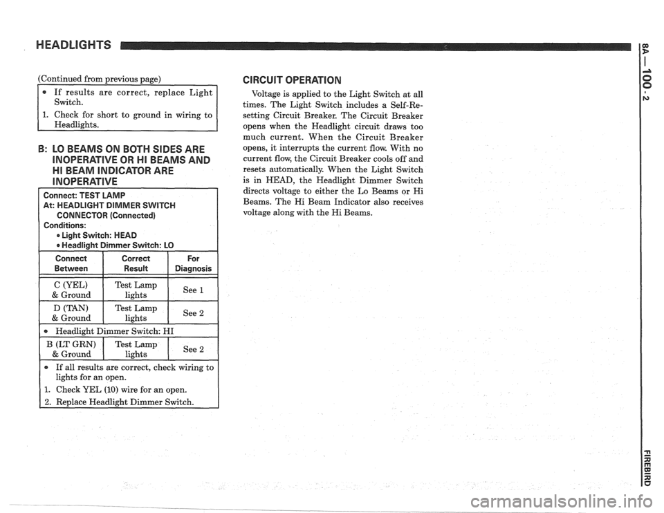
HEADLIGHTS
(Continued from previous page)
If results are correct, replace Light
Switch.
short to ground in wiring to
B: LO BEAMS ON BOTH SIDES ARE
INOPERATIVE OR HI BEAMS AND
Ell BEAM INDICATOR ARE
Connect: TEST LAMP
At: HEADLIGHT DIMMER SWITCH
CONNECTOR (Connected)
Conditions:
0 Light Switch: HEAD
0 Headlight Dimmer Switch: LO
Connect Correct For
0 If all results are correct, check wiring to
lights for an open.
1. Check YEL (10) wire for an open.
2. Replace Headlight Dimmer Switch.
CIRCUIT OPERATION
Voltage is applied to the Light Switch at all
times. The Light Switch includes a Self-Re-
setting Circuit Breaker. The Circuit Breaker
opens when the Headlight circuit draws too
much current. When the Circuit Breaker
opens, it interrupts the current flow. With no
current flow, the Circuit Breaker cools off and
resets automatically. When the Light Switch
is in
HEAD, the Headlight Dimmer Switch
directs voltage to either the Lo Beams or
Hi
Beams. The Hi Beam Indicator also receives
voltage along with the
Hi Beams.
Page 1452 of 1825
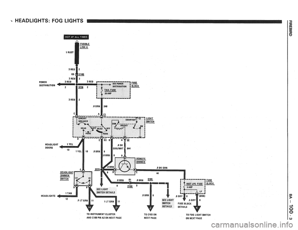
HEADLIGHTS: FOG LlGHTS
DISTRIBUTION
FUSE
- BLOCK -
TO INSTRUMENT CLUSTER
TO C103 ON AND ClOO PIN A2 ON NEXT PAGE
NEXT PAGE TO
FOG LIGHT SWITCH
ON NEXT PAGE
Page 1453 of 1825
Page 1454 of 1825
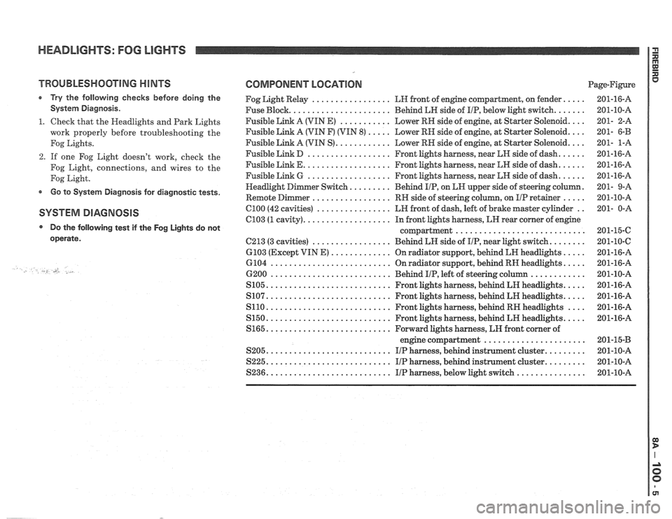
HEADLIGHTS: FOG LIGHTS
TROUBLESHOOTING HINTS
r Try the following checks before doing the
System Diagnosis
.
1 . Check that the Headlights and Park Lights
work properly before troubleshooting the
Fog Lights
.
2 . If one Fog Light doesn't work, check the
Fog Light. connections. and wires to the
Fog Light
.
Go to System Diagnosis for diagnostic tests .
SYSTEM DIAGNOSIS
Do the following test if the
operate
.
-., U .
Fog Lights do not
COMPONENT LOCATION Page-Figure
Fog Light Relay
................. LH front of engine compartment. on fender .....
Fuse Block ...................... Behind LH side of IIP. below light switch .......
Fusible Link A (VIN E) ........... Lower RN side of engine. at Starter Solenoid ....
Fusible Link A (VIN F) (VIN 8) ..... Lower RH side of engine. at Starter Solenoid ....
Fusible Link A (VIN S) ............ Lower RH side of engine. at Starter Solenoid ....
Fusible Link D .................. Front lights harness. near kH side of dash ......
Fusible Link E ................... Front lights harness. near LH side of dash ......
Fusible Link 6 .................. Front lights harness. near LN side of dash ......
......... . er Switch Behind IIP. on EN upper side
of steering column
Remote
Dimmer ................. RH side of steering column. on IIP retainer ..... .
C100 (42 cavities) ................ LH front of dash. left of brake master cylinder ..
C103 (1 cavity) ................... In front lights harness. LH rear corner of engine
compartment
............................
C213 (3 cavities) ................. Behind LH side of IIP. near Light switch ........
6103 (Except VIN E) ............. On radiator support. behind LR headlights .....
6104 .......................... On radiator support. behind RN headlights .....
6200 .......................... Behind IIP. left of steering column ............
S105 ........................... Front lights harness. behind LH headlights .....
S107 ........................... Front lights harness. behind LH headlights .....
S110 ........................... Front lights harness. behind RH headlights ....
S150 ........................... Front lights harness. behind LH headlights .....
S165 ........................... Forward lights harness. LH front corner of
engine compartment
......................
S205 ........................... I/P harness. behind instrument cluster .........
S225 ........................... I/P harness. behind instrument cluster .........
S236 ........................... IIP harness. below light switch ...............
Page 1455 of 1825
HEADLIGHTS: FOG LIGHTS
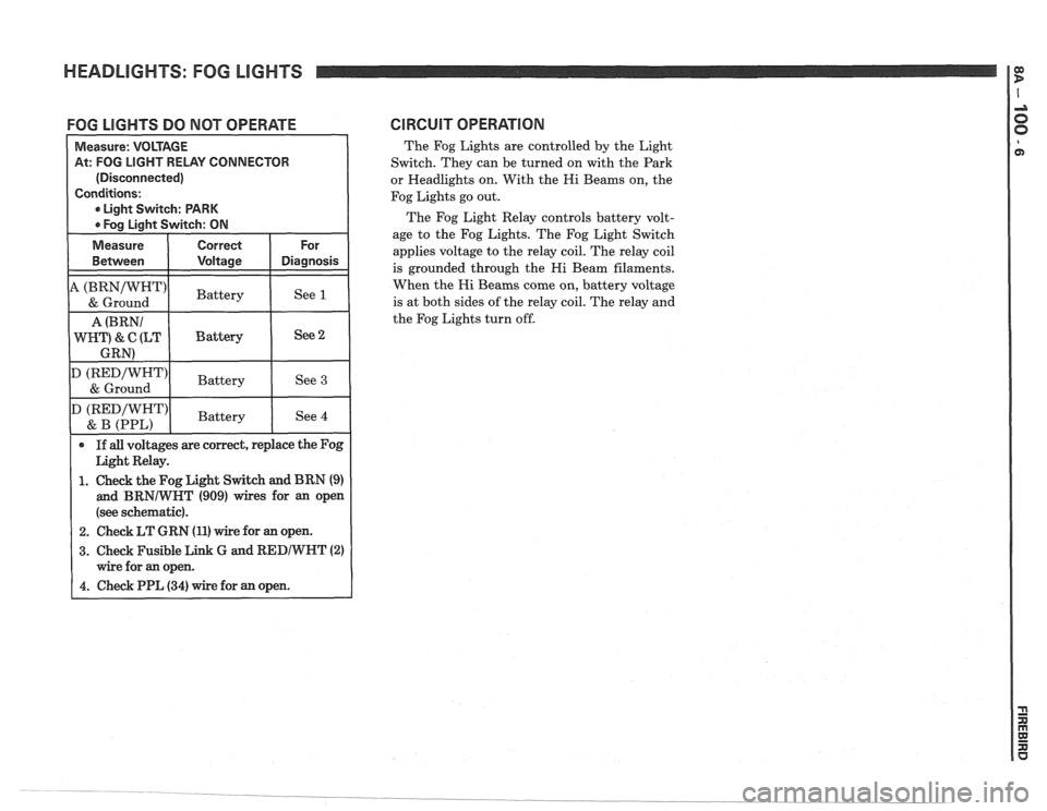
FOG LIGHTS DO NOT OPERATE CIRCUIT OPERATlON
The Fog Lights are controlled by the Light
Switch. They can be turned on with the Park
or Headlights on. With the Hi Beams on, the
Fog Lights go out.
The Fog Light Relay controls battery volt-
age to the Fog Lights. The Fog Light Switch
applies voltage to the relay coil. The relay coil
is grounded through the Hi Beam filaments.
When the Hi Beams come on, battery voltage
is at both sides of the relay coil. The relay and
the Fog Lights turn off.
At: FOG LIGHT RELAY CONNECTOR
(Disconnected)
1. Check the Fog Light Switch and BRN (9)
and BRNIWNT (909) wires for an open
(see schematic).
2. Check LT GRN (11) wire for an open.
3. Check Fusible Link G and RED/WNT (2)
Page 1456 of 1825

Page 1457 of 1825
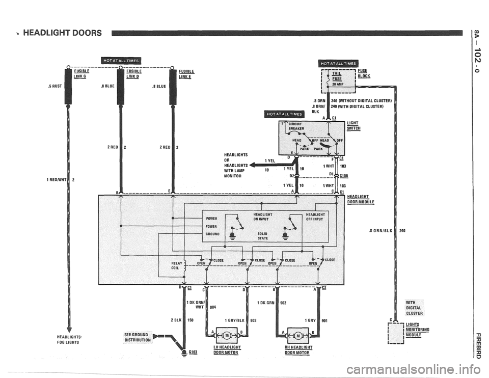
a HEADLIGHT DOORS l e
----- FUSIBLE
HEADLIGHTS: FOG LIGHTS
Page 1458 of 1825
HEADLIGHT DOORS
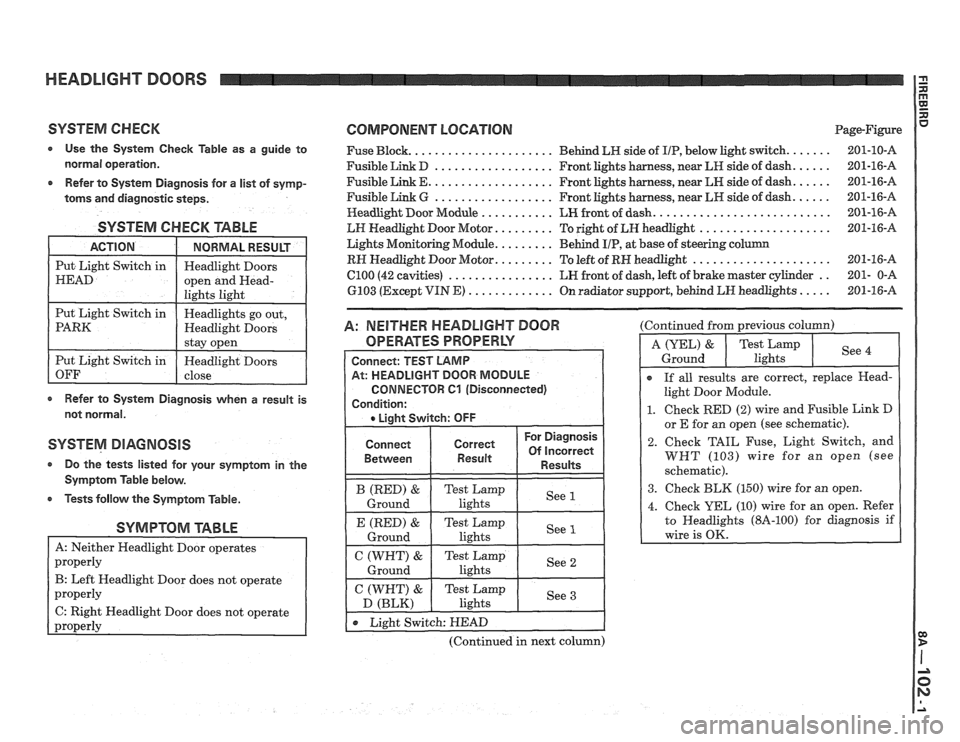
SYSTEM CHECK COMPONENT LOCATION Page-Figure
Use the System Check Table as a guide to Fuse Block. ..................... Behind LN side of IIP, below light switch. ...... 201-10-A
normal operation. Fusible Link D .................. Front lights harness, near LR side of dash. ..... 201-16-A
..... .................. Refer to System Diagnosis for a list of symp- Fusible Link E. Front lights harness, near LN side of dash. 201-16-A
..... .................. toms and
diagnostic steps. Fusible Link G Front lights harness, near LH side of dash. 201-16-A
.......................... Headlight
Door Module ........... LH front of dash. 201-16-A
SYSTEM CHECK TABLE
Refer to System Diagnosis when a result is
not normal.
SYSTEM DIAGNOSIS
a Do the tests listed for your symptom in the
Symptom Table below.
Tests follow the Symptom Table.
SYMPTOM TABLE
B: Left Headlight Door does not operate
C: Right Headlight Door does not operate
-
LH Headlight Door Motor. ........ To right of LH headlight .................... 201-16-A
Lights Monitoring Module.
........ Behind UP, at base of steering column
RH Headlight Door Motor. ........ To left of RN headlight ..................... 201-16-A
C100 (42 cavities) ................ LH front of dash, left of brake master cylinder .. 201- 0-A
6103 (Except VIN
E) ............. On radiator support, behind LN headlights ..... 201-16-A
A: NEITHER HEADLIGHT DOOR
OPERATES PROPERLY
Connect
Between
(Continued in next column) (Continued
from previous column)
I
r If all results are correct, replace Head-
light Door Module.
1. Check RED (2) wire and Fusible Link D
or E for an owen (see schematic).
2. Check TAIL Fuse, Light Switch, and
WHT (103) wire for an open (see
schematic).
3. Check BLK (150) wire for an open.
Page 1459 of 1825
HEADLIGHT DOORS
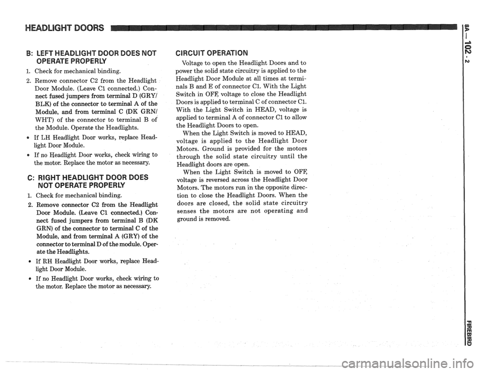
B: LEFT HEADLIGHT DOOR DOES NOT
OPERATE PROPERLY
1. Check for mechanical binding.
2. Remove connector C2 from the Headlight
Door Module. (Leave
C1 connected.) Con-
nect fused jumpers from terminal D
(GRYI
BLK) of the connector to terminal A of the
Module, and from terminal C (DK GRNI
WHT) of the connector to terminal
B of
the Module. Operate the Headlights.
0 If LH Headlight Door works, replace Head-
light Door Module.
0 If no Headlight Door works, check wiring to
the motor. Replace the motor as necessary.
6: RIGHT HEADLIGHT DOOR DOES
NOT OPERATE PROPERLY
1. Check for mechanical binding.
2. Remove connector C2 from the Headlight
Door Module. (Leave
C1 connected.) Con-
nect fused jumpers from terminal B (DK
GRN) of the connector to terminal
C of the
Module, and from terminal
A (GRY) of the
connector to terminal D of the module. Oper-
ate the Headlights.
If RH Headlight Door works, replace Head-
light Door Module.
0 If no Headlight Door works, check wiring to
the motor. Replace the motor as necessary.
GlRGUlT OPERATION
Voltage to open the Headlight Doors and to
power the solid state circuitry is applied to the
Headlight Door Module at all times at termi-
nals
B and E of connector 61. With the Light
Switch in OFF, voltage to close the Headlight
Doors is applied to terminal C of connector
C1.
With the Light Switch in HEAD, voltage is
applied to terminal A of connector
C1 to allow
the Headlight Doors to open.
When the Light Switch is moved to HEAD,
voltage is applied to the Headlight Door
Motors. Ground is provided for the motors
through the solid state circuitry until the
Headlight doors are open.
When the Light Switch is moved to OFF,
voltage is reversed across the Headlight Door
Motors. The motors run in the opposite direc-
tion to close the Headlight Doors. When the
doors are closed, the solid state circuitry
senses the motors are not operating and
ground is removed.
Page 1460 of 1825
