PONTIAC FIERO 1988 Service Repair Manual
Manufacturer: PONTIAC, Model Year: 1988, Model line: FIERO, Model: PONTIAC FIERO 1988Pages: 1825, PDF Size: 99.44 MB
Page 1411 of 1825
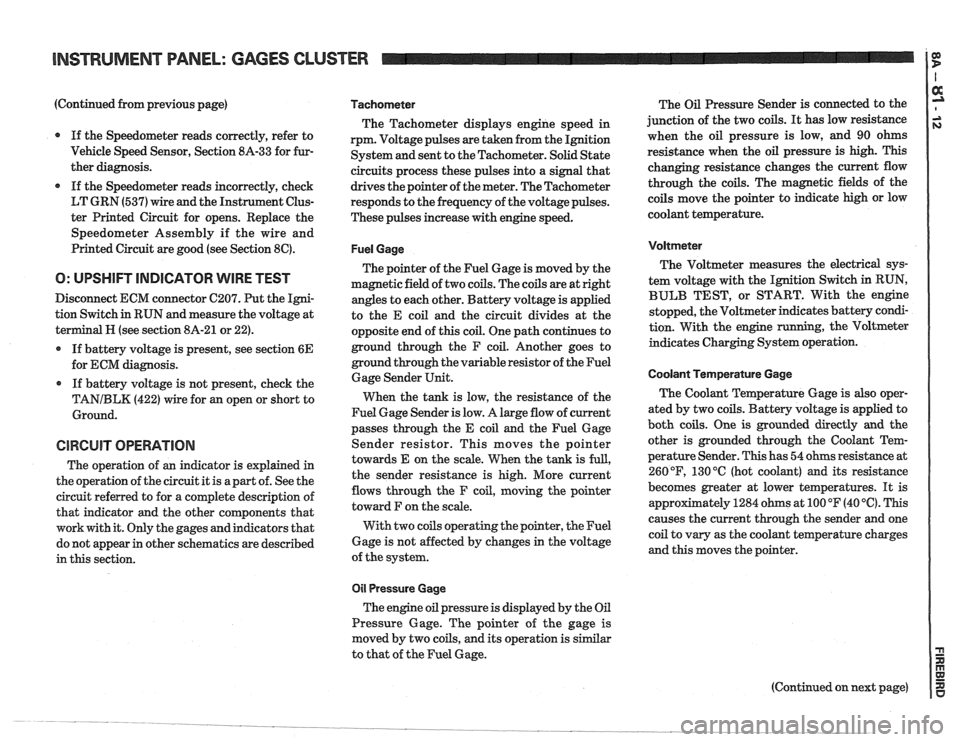
(Continued from previous page)
If the Speedometer reads correctly, refer to
Vehicle Speed Sensor, Section
8A-33 for fur-
ther diagnosis.
If the Speedometer reads incorrectly, check
LT GRN (537) wire and the Instrument Clus-
ter Printed Circuit for opens. Replace the
Speedometer Assembly if the wire and
Printed Circuit are good (see Section
8C).
O: UPSHIFT INDICATOR WIRE TEST
Disconnect ECM connector C207. Put the Igni-
tion Switch in RUN and measure the voltage at
terminal
H (see section 8A-21 or 22).
If battery voltage is present, see section
6E
for ECM diagnosis.
If battery voltage is not present, check the
TANIBLK (422) wire for an open or short to
Ground.
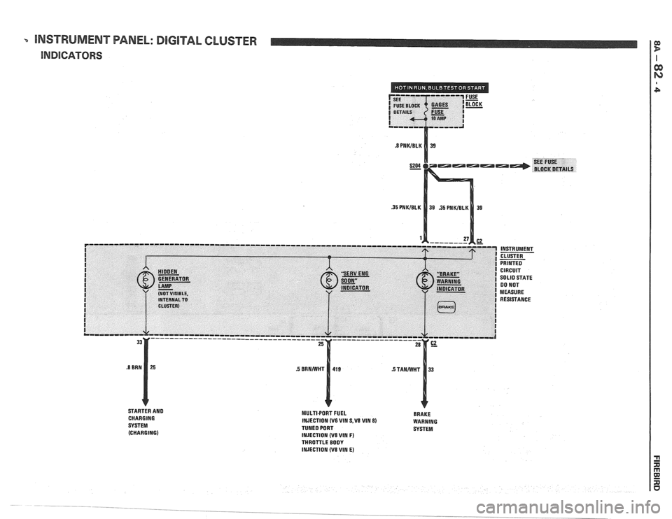
CIRCUIT OPERATION
The operation of an indicator is explained in
the operation of the circuit it is apart of. See the
circuit referred to for a complete description of
that indicator and the other components that
work with it. Only the gages and indicators that
do not appear in other schematics are described
in this section.
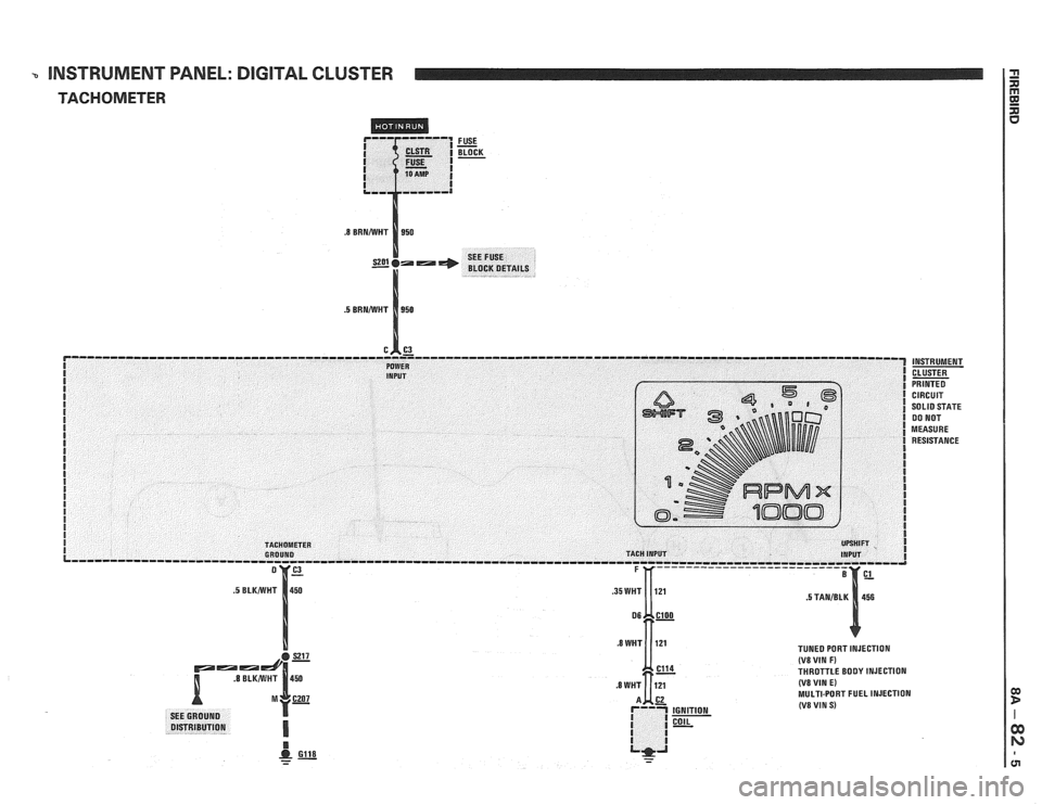
Tachometer
The Tachometer displays engine speed in
rpm. Voltage pulses are taken from the Ignition
System and sent to the Tachometer. Solid State
circuits process these pulses into a signal that
drives the pointer of the meter. The Tachometer
responds to the frequency of the voltage pulses.
These pulses increase with engine speed.
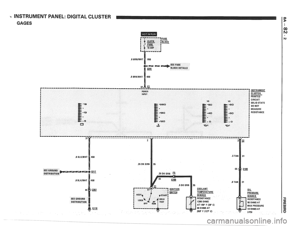
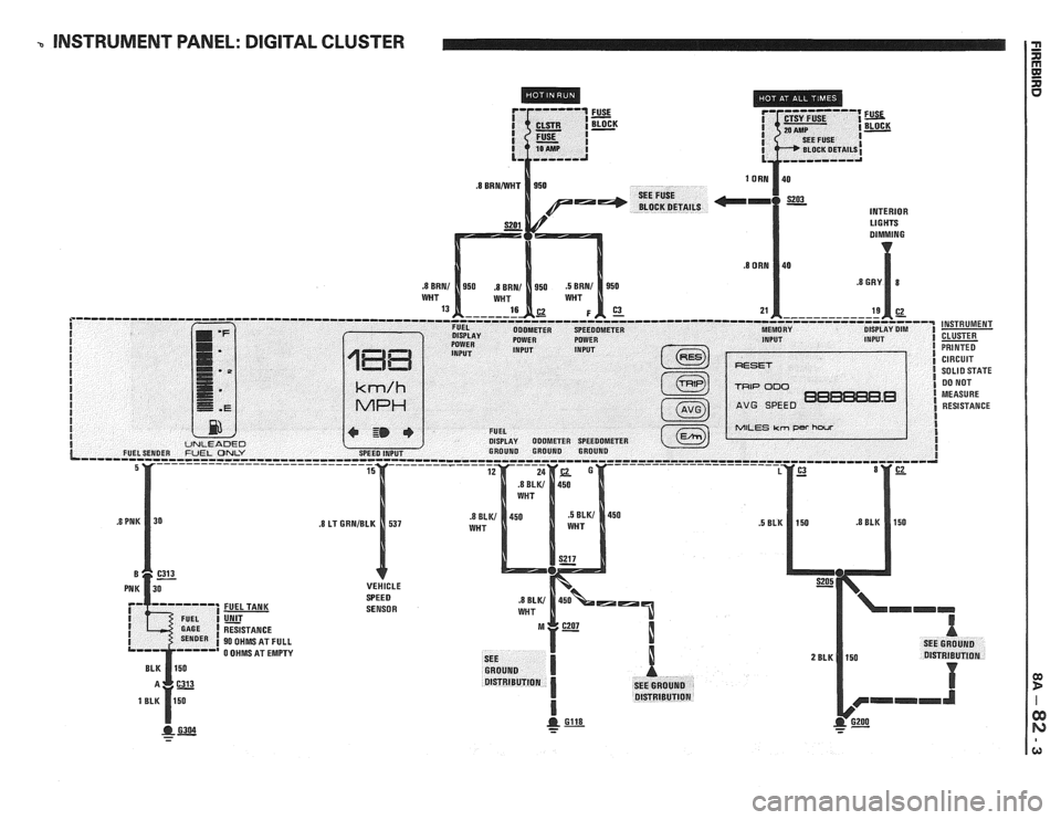
Fuel Gage
The pointer of the Fuel Gage is moved by the
magnetic field of two coils. The coils are at right
angles to each other. Battery voltage is applied
to the E coil and the circuit divides at the
opposite end of this coil. One path continues to
ground through the F coil. Another goes to
ground through the variable resistor of the Fuel
Gage Sender Unit.
When the tank is low, the resistance of the
Fuel Gage Sender is low. A large flow of current
passes through the E coil and the Fuel Gage
Sender resistor. This moves the pointer
towards E on the scale. When the tank is
full,
the sender resistance is high. More current
flows through the F coil, moving the pointer
toward F on the scale.
With two coils operating the pointer, the Fuel
Gage is not affected by changes in the voltage
of the system.
011 Pressure Gage
The engine oil pressure is displayed by the Oil
Pressure Gage. The pointer of the gage is
moved by two coils, and its operation is similar
to that of the Fuel Gage. The
Oil Pressure Sender is connected to the
junction of the two coils.
It has low resistance
when the oil pressure is low, and 90 ohms
resistance when the oil pressure is high. This
changing resistance changes the current flow
through the coils. The magnetic fields of the
coils move the pointer to indicate high or low
coolant temperature.
Voltmeter
The Voltmeter measures the electrical sys-
tem voltage with the Ignition Switch in RUN,
BULB TEST, or START. With the engine
stopped, the Voltmeter indicates battery condi-
tion. With the engine
running, the Voltmeter
indicates Charging System operation.
Coolant Temperature Gage
The Coolant Temperature Gage is also oper-
ated by two coils. Battery voltage is applied to
both coils. One is grounded directly
and the
other is grounded through the Coolant Tem-
perature Sender. This has 54 ohms resistance at
260
OF, 130 "C (hot coolant) and its resistance
becomes greater at lower temperatures. It is
appr~ximately 1284 ohms at 100 OF (40 '6). This
causes the current through the sender and one
coil to vary as the coolant temperature charges
and this moves the pointer.
Page 1412 of 1825
INSTRUMENT PANEL: GAGES CLUSTER
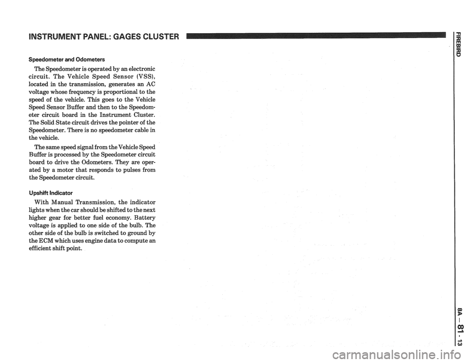
Speedorneter and Odometers
The Speedometer is operated by an electronic
circuit. The Vehicle Speed Sensor (VSS),
located in the transmission, generates an AC
voltage whose frequency is proportional to the
speed of the vehicle. This goes to the Vehicle
Speed Sensor Buffer and then to the Speedom-
eter circuit board in the Instrument Cluster.
The Solid State circuit drives the pointer of the
Speedometer. There is no speedometer cable
in
the vehicle.
The same speed signal from the Vehicle Speed
Buffer is processed by the Speedometer circuit
board to drive the Odometers. They are oper-
ated by a motor that responds to pulses from
the Speedometer circuit.
UpshiN Indicator
With Manual Transmission, the indicator
lights when the car should be shifted to the next
higher gear for better fuel economy. Battery
voltage is applied to one side of the bulb. The
other side of the bulb is switched to ground by
the ECM which uses engine data to compute an
efficient shift point.
Page 1413 of 1825
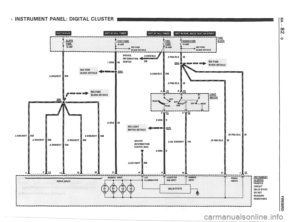
INSTRUMENT PANEL: DIGITAL CLUSTER
I
I
I I SEE FUSE 20 AMP SEE FUSE I
BLOCK DETAILS
CIRCUIT SOLID STATE 00 NOT
MEASURE RESISTANCE
Page 1414 of 1825
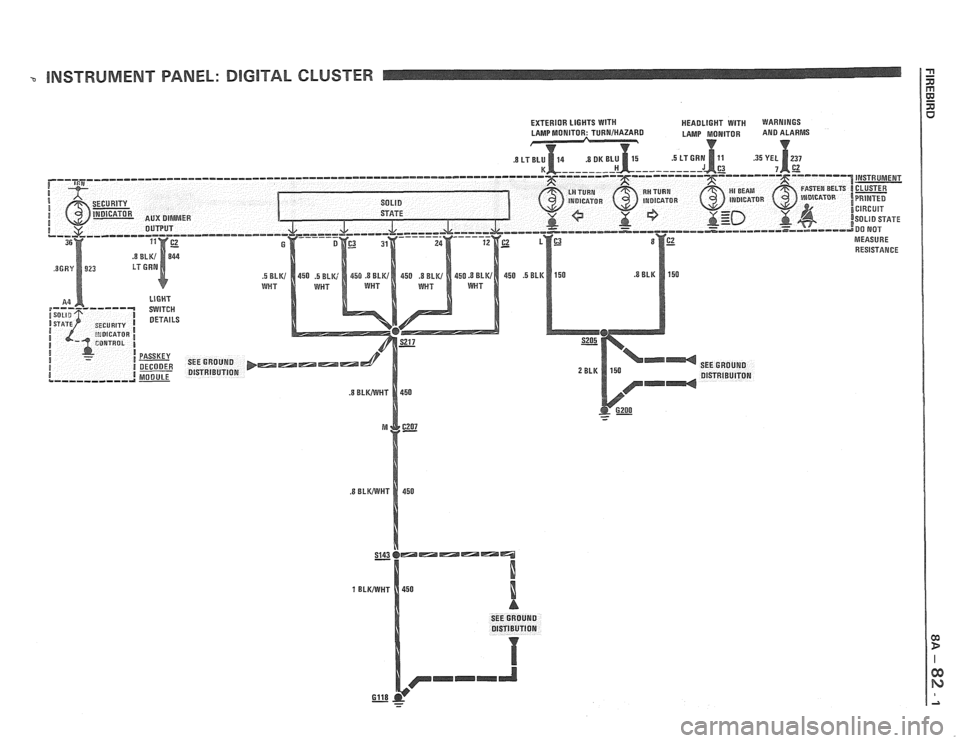
- INSTRUMENT PANEL: DlGlTAL CLUSTER
SEE GROUND
Gll8 - - -
Page 1415 of 1825
INSTRUMENT PANEL: DIGITAL CLUSTER
GAGES
MAX PRESSURE
Page 1416 of 1825
b INSTRUMENT PANEL: DIGITAL CLUSTER
INTERIOR Ll G HTS
SENSOR
- - -
Page 1417 of 1825
-. INSTRUMENT PANEL: DIGlTAL CLUSTER
INDICATORS
STARTER AND
CHARGING
SYSTEM (CHARGING) MULTIPORT FUEL BRAKE
INJECTION (V6 WIN S,V8 VIM 8) WARNING
TUNED PORT SYSTEM
INJECTION
(V8 VIN F) THROTTLE BODY
INJECTION (V8 WIN E)
Page 1418 of 1825
3 INSTRUMENT PANEL: DIGITAL CLUSTER
TACHOMETER
FUSE - BLOCK -
INSTRUMENT
CLUSTER
PRINTED CIRCUIT
SO
LID STATE 00 NOT
MEASURE RESISTANCE
TUNED PORT INJECTION (V8 VIN F) THROTTLE BODY INJECTION (VB VIN E) MULTI-PORT FUEL INJECTION (V8 VIN S)
Page 1419 of 1825
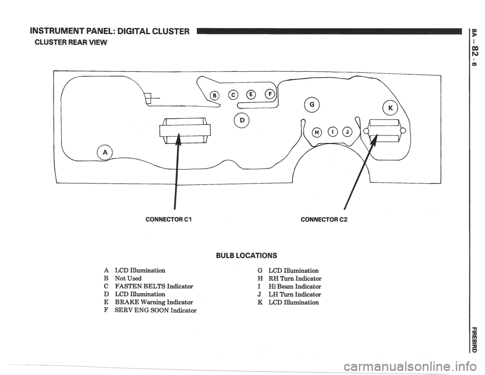
[NSTRUMENT WNEL: DIGITAL CLUSTER
CLUSTER REAR VlEW
CONNECTOR 61 CONNECTOR 62
BULB LOCATIONS
A LCD Illurnination
B Not Used
C FASTEN BELTS Indicator
D LCD Illumination
E BRAKE Warning Indicator
F SERV ENG SOON Indicator G
LCD Illumination
Indicator
Indicator
Indicator
K LCD Illumination
Page 1420 of 1825
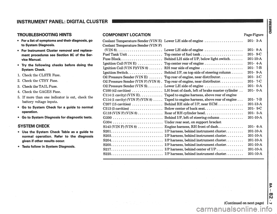
INSTRUMENT PANEL: DIGITAL CLUSTER a
TROUBLESHOOTING HINTS COMPONENT LOCATION u Page-Figure
0 For a list of symptoms and their diagnosis. go
to System Diagnosis
.
0 For Instrument Cluster removal and replace-
ment procedures see Section
86 of the Ser-
vice Manual
.
* Try the following checks before doing the
System Check
.
1 . Check the CLSTR Fuse .
2 . Check the CTSY Fuse .
3 . Check the TAIL Fuse .
Coolant Temperature Sender (VIN E) Lower LH side of engine ....................
Coolant Temperature Sender (VIN F)
(VIN 8)
........................ Lower LH side of engine ....................
Fuel Tank Unit .................. Top center of fuel tank ......................
Fuse Block ...................... Behind LH side of IIP. below light switch .......
Ignition Coil (VIN E) ............. Top center rear of engine ....................
Ignition Coil (VIN F)(VIN 8) ....... RH rear side of engine ......................
Ignition Switch .................. Behind IIP. on top side of steering column ......
Oil Pressure Sender (VIN E) ....... Top rear of engine. near distributor ............
Oil Pressure Sender (VIN F) (VIN 8) . Top rear of engine. near distributor ............
Oil Pressure Sender (VIN S) ........ Lower LH side of engine ....................
................ .. 4 . Check the GAGES Fuse . el00 (42 cavities) LH
front of dash. left of brake master cylinder 201- 0-A
C114
(1 cavity) (VIN E) ............ Taped to engine harness. above rear of engine
5 . If more than one indicator is out. check the C114 (1 cavity) (VIN F) (VIN 8) ..... Taped to engine harness. above rear of engine ... 201- 7-B
battery voltage inputs . . C207 (15 cavities) ................ Behind RH side of IIP near ECM ............. 201-13-A
................. .................... * Go to System Check for a guide to C313 (3 cavities) Below
center of back seat 201- 9-C operation . 6118 (VIN F) (VIN 8) ............. Rear of RH cylinder head .................... 201- 5-A
0 Go to System Diagnosis for diagnostic tests . 6200 .......................... Behind IIP. left of steering column ............ 201-10-A
6304
.......................... Under rear seat. on support bracket
SYSTEM CHECK S143 (VIN F) (VIN 8) ............. Engine harness. RH front of dash ............. 201- 6-A
0 Use the System Check able as a guide to S201 ........................... IIP harness. behind instrument cluster ......... 201-10-A
normal operation . Refer to the diagnosis S203 ........................... I/P harness. behind instrument cluster ......... 201-10-A
........................... ......... given if other results occur . S204 IIP harness. behind instrument cluster 201-10-A
........................... ......... Tests follow in System Diagnosis . S205 IIP harness. behind instrument cluster 201-10-A
S217 ........................... IIP harness. behind center of IIP .............. 201-10-A
S225 ........................... IIP harness. behind instrument cluster ......... 201-10-A
(Continued on next page)