bulb PONTIAC FIERO 1988 Service User Guide
[x] Cancel search | Manufacturer: PONTIAC, Model Year: 1988, Model line: FIERO, Model: PONTIAC FIERO 1988Pages: 1825, PDF Size: 99.44 MB
Page 665 of 1825
6E3-A-92 2.8b (VIN SI DRIVEABILITY AND EMISSIONS
TO OIL PRESS. SW.
&FUEL PUMP RELAY
FUSE
& HOLDER BATTERY 12
V
.. am.. . FUSIBLE LINK 15 WAY
439
PNWBLK
- 419 BUNNVHT
SERIAL DATA
451
WHTIBLK
450 BLWHT
ALDL CONNECTOR
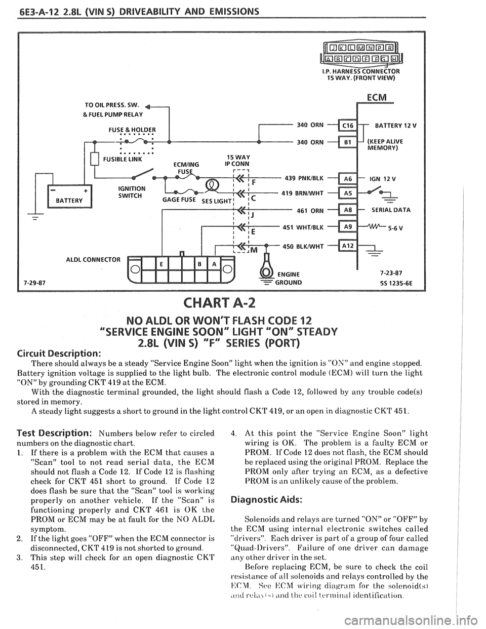
CHART A-2
NO ALDL OR WONT FLASH CODE 12
""SERVICE ENGlNE SOON" MGHT ""8N13SPEADY
2.8L (VIN S) ""FYSERlES (PORT)
Circuit Description:
There should always be a steady "Service Engine Soon" light when the ignition is "ON" and engine stopped.
Battery ignition voltage is supplied to the light bulb. The electronic control module
(ECM) will turn the light
"ON" by grounding CKT
419 at the ECM.
With the diagnostic terminal grounded, the light should flash
a Code 12, followed by any trouble code(s)
stored in memory.
A steady light suggests a short to ground in the light control CKT 419, or an open in diagnostic CKT 451.
Test Description: Numbers below refer to circled
numbers on the diagnostic chart.
1. If there is a problem with the ECM that causes a
"Scan" tool to not read serial data, the ECM
should not flash a Code 12. If Code 12 is flashing
check for CKT
451 short to ground. If Code 12
does flash be sure that the "Scan" tool is working
properly on another vehicle. If the "Scan" is
functioning properly and CKT 461 is OK the
PROM or ECM may be at fault for the NO
AL,DI,
symptom.
2. If
the light goes "OFF" when the ECM connector is
disconnected, CKT 419 is not shorted to ground.
3. This step will check for an open diagnostic CKrl'
451.
4. At this point the "Service Engine Soon" light
wiring is OK. The problem is a faulty ECM or
PROM. If Code 12 does not flash, the ECM should
he replaced using the original PROM. Replace the
PROM only after trying an ECM, as a defective
PROM is an unlikely cause of the problem.
Diagnostic Aids:
Solenoids and relays are turned "ON" or "OFF" by
the ECM using internal electronic switches called
"drivers". Each driver is part of a group of four called
"Quad-l)rivers". Failure of one driver can damage
any other driver in the set.
Hefore replacing ECM, be sure to check the coil
resistance of
all solenoids and relays controlled by the
14:CM. Set: I':C%f wiring cliugrntn for the solcnoid(s)
.c~~cl rel;~ (-1 ~ititl lllc coil tcrtriitlul itlentilication.
Page 786 of 1825
DRIVEABILITY AND EMlSSlONS 2.8L (VIN %I 6E3-C8-1
TRANSMISSION CONVERTER CLUTCH (KC) SYSTEM
AND MANUAL
TRANSMISSION SHIFT LIGHT
CONTENTS
GENERAL DESCRIPTION ................ C8-1 DIAGNOSIS ..........ee...ee....e.e. C8-1
PURPOSE ......................... C8-1 SHIFT LIGHT (MIT) DESCRIPTION ........ C8-1
OPERATION ....................... C8-1 DIAGNOSIS ....................... .. C8-1
ON-CAR SERVICE ...................*. C8-1
GENERAL DESCRIPTION
PURPOSE
The transmission converter clutch (TCC) svstem
uses a solenoid operated valve in the automatic
transmission to couple the engine flywheel to the
output shaft of the transmission thru the torque
converter. This reduces the slippage losses in the
converter, which increases fuel economy.
OPERATION
For the converter clutch to apply, two conditions
must be met:
o Internal transmission fluid pressure must be
correct. For information on internal transmission
operation, see Section
"7A". This section will cover
only the electrical operation of the TCC system.
@ The ECM grounds a switch internally to turn on a
solenoid in the transmission. This moves a check
ball, which will allow the converter clutch to
apply, if the hydraulic pressure is correct, as
described above.
The ECM controls the TCC apply solenoid by
looking at several sensors:
@ Speedo Buffer Sensor (also called vehicle speed
sensor
(VSS). Speed must be above a certain value
before the clutch can apply.
@ Coolant Temperature Sensor. Engine must be
warmed up before clutch can apply about
65OC
(149°F').
Throttle position sensor ('I'PS). After the
converter clutch applies, the
HCM uses the
information from the TPS to release thc clutch
when the car is accelerating or decelerating at a
certain rate.
@ 'I'he brake switch is also part of the 'I'CC circuit as
it will remove battery voltage to the 'KC solenoid
when the brake pedal is depressed.
@ Gear Select Switch. The 4th gear switch is used to
send a signal to the
ECM telling it when the
transmission is in 4th gear. The ECM uses this
information to vary the conditions under which
the clutch applies or releases.
IIowever, the
transmission does not have to be in fourth gear in
order for the ECM to turn the clutch on.
If the converter clutch is applied at all times. the
engine will stall immediately, just as in
u manual
transmission with the clutch applied.
If the converter clutch does not apply, fuel
ecomony
may be lower than expected. If the vehicle
speed sensor fails, the TCC will not apply. If the 4th
gear switch does not operate, the TCC may not apply
at the right time.
DIAGNOSIS
The diagnosis of the TCC system is covered in
CHART C-8
. If the ECM detects a problem in the
system,
a Code 24 should set. In this case see Code 24
CHART.
SHIFT LIGHT (MiT) DESCRIPTION
'The purpose of the shift light is to provide a
display which indicates the optimum fuel economy
point for up
shifling the manual transmission based
on engine speed
and load. 'I'he display is a lamp on the
instrument panel. Activation of the ECM driver turns
the lamp
on.
'I'he shift light circuit can he checlted using
CHAR?' C-8C.
ON-CAR SERVICE
@ See Section "8B" if the shift light bulb needs
replacement.
@ See Section "6E" to repair wiring problem.
@ See Section "6C" if ECM is to be replaced.
Page 788 of 1825
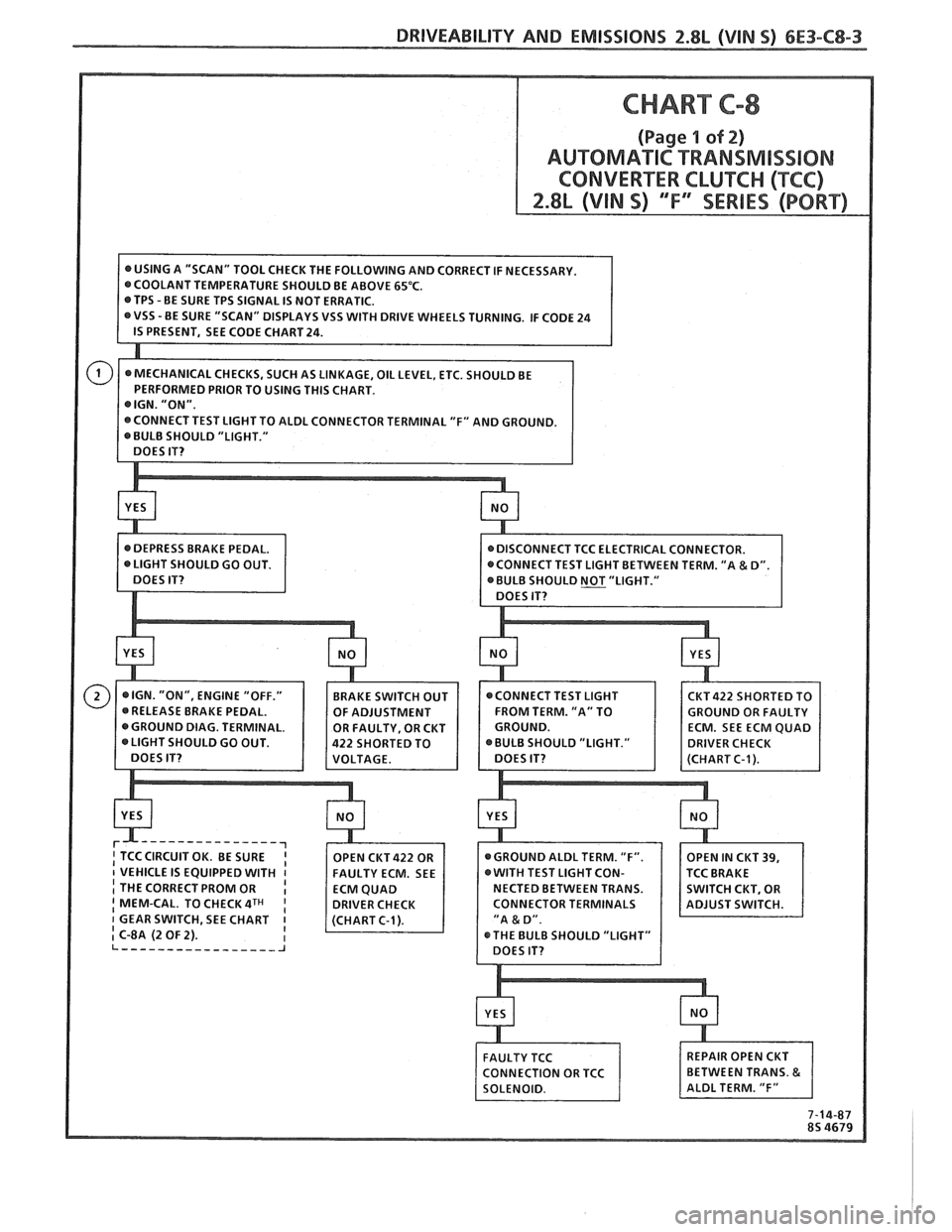
CHART C-8
(Page 1 of 2)
AUTOMATIC TRANSMlSS18N
CONVERTER CLUKC (("FCC)
VSS WITH DRIVE WHEELS TURNING. IF CODE 24
BULB SHOULD "LIGHT."
CKT422 SHORTED TO
FROM TERM. "A" TO
OULD GO OUT.
-------------
I THE CORRECT PROM OR I I MEM-CAL. TO CHECK 4TH CONNECTOR TERMINALS
1 GEAR SWITCH, SEE CHART
I C-8A (2 OF 2).
7-14-87
8s 4679
Page 813 of 1825
TO MAF SENSOR
POWER & BURN-OFF
RELAY, OIL PRESS. SW.
.....-
439 PNKIBLK
419 BRNNVHT
SERIAL DATA
451 WHTIBLK
450
BLWHT
ALDL CONNECTOR
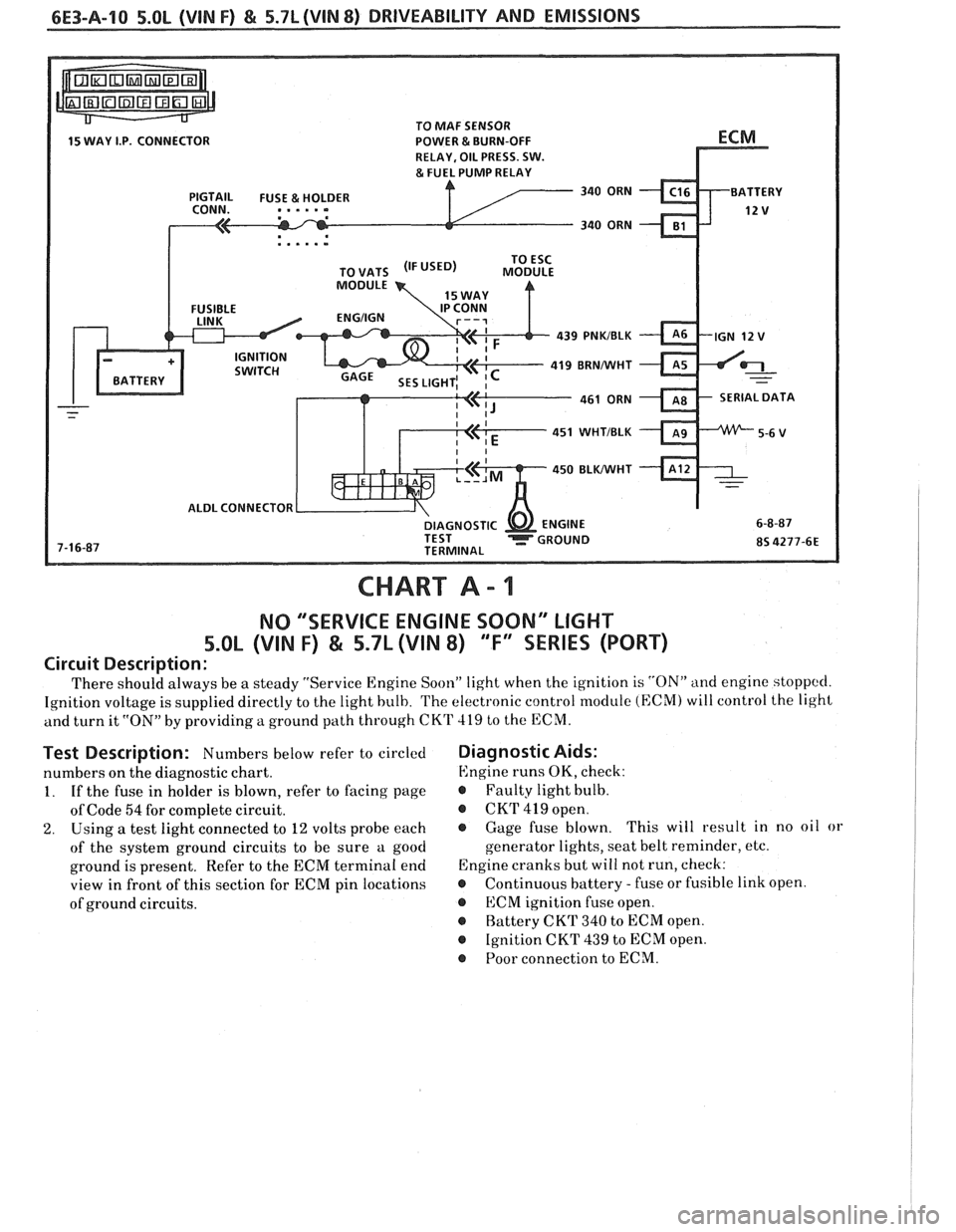
CHART A - 1
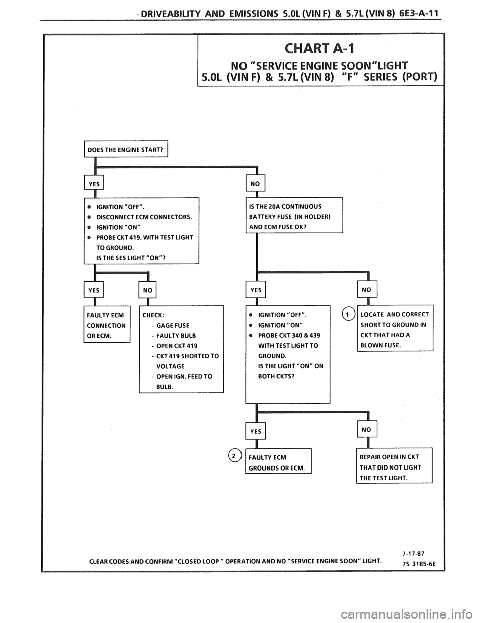
NO "'SERVICE ENGINE SOON" LIGHT
5.OL (VIN F) & 5.7L (VIN 8) "F'XSEBIE'S (PORT)
Circuit Description:
There should always be a steady "Service Engine Soon" light when the ignition is "ON" and engine stoppccl.
Ignition voltage is supplied directly to the light bulb. The electronic control module (ECM) will control the light
and turn it
"ON" by providing a ground path through CKT 419 to the ECM.
Test Description: Numbers below refer to circled
numbers on the diagnostic chart.
1. If the fuse in holder is blown, refer to facing page
of Code
54 for complete circuit.
2. Using a test light connected to 12 volts probe each
of the system ground circuits to be sure a good
ground is present. Refer to the ECM terminal end
view in front of this section for ECM pin locations
of ground circuits.
Diagnostic Aids:
Engine runs OK, check:
r Faulty light bulb.
@ CKrI' 419 open.
@ Gage fuse blown. This
will result in no oil or
generator lights, seat belt reminder, etc.
Engine cranks but will not run, check:
r Continuous battery - fuse or fusible link open.
@ ECM ignition fuse open.
r Battery CKT 340 to ECM open.
@ Ignition CKT 439 to ECM open.
@ Poor connection to ECM.
Page 814 of 1825
DRIVEABILITY AND EMISSIONS 5.0L (VIN F) & 5.7L (WIN 8) 6E3-A-11
@ DISCONNECT ECM CONNECTORS.
e IGNITION "ON"
PROBE
CKT419, WITH TEST LIGHT
TO GROUND.
- GAGE FUSE
- FAULTY BULB PROBE
CKT 340 & 439 CKT
THAT HAD A
- OPEN CKT 419 WITH TEST LIGHT TO
- CKT 419 SHORTED TO
IS THE LIGHT "ON" ON
- OPEN IGN. FEED TO
HAT DID NOT LIGHT
Page 815 of 1825
6E3-A-12 5.OL (VIN F) & 5.7L (VIN 8) DRIVEABILITY AND EMISSIONS
TO MAF SENSOR
POWER & BURN-OFF
, . . . . .
439 PNWBLK
419 BRNNVHT
SERIAL DATA
451
WHTIBLK
450 BLKIWHT
ALDL CONNECTOR
CHART A-2
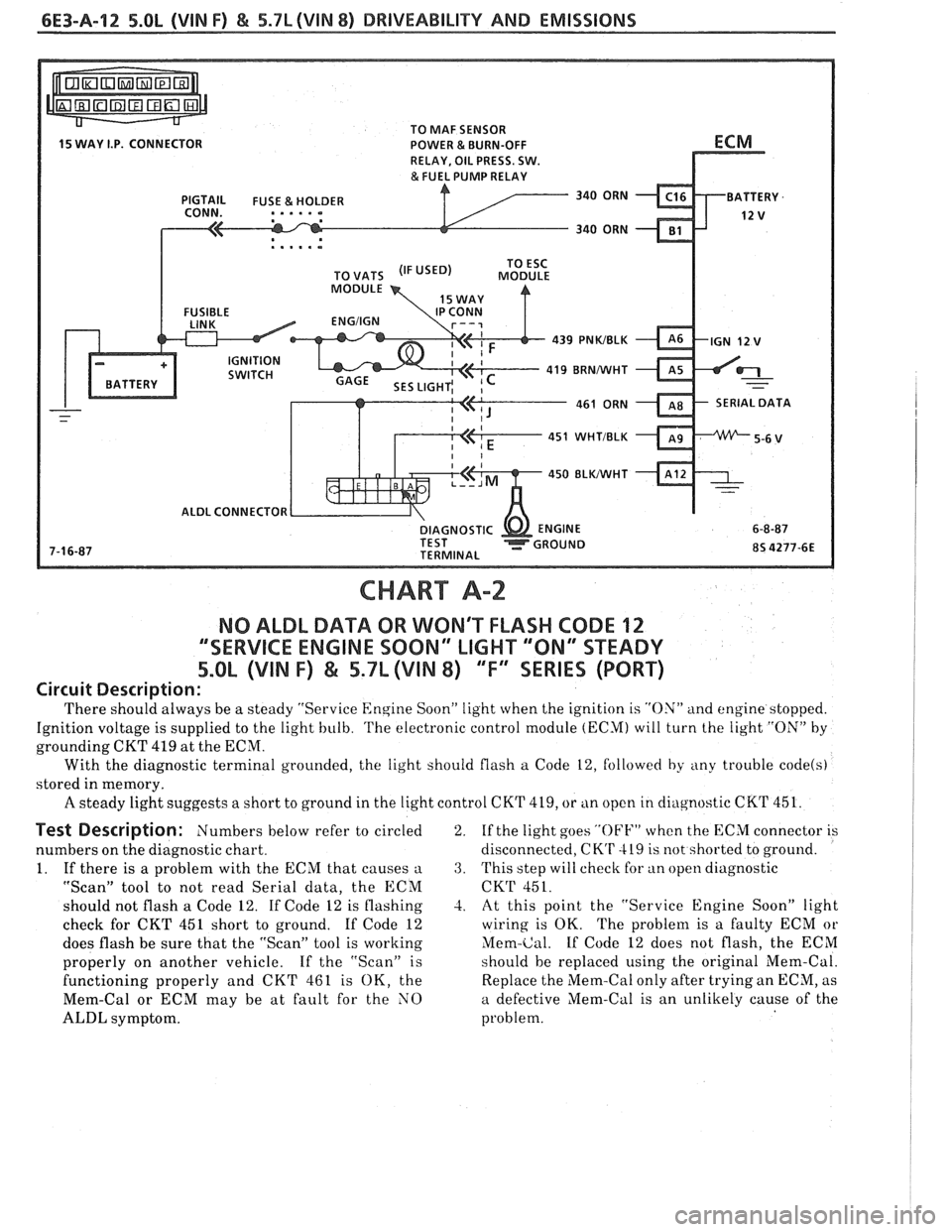
NO ALDL DATA OR WON'T FLASH CODE 12
""SERVICE ENGINE SOON" LIGHT '"ON" STEADY
5.OL (VIN F) & 5.7L (VIN 8) ""FYEERIES (PORT)
Circuit Description:
'I'here should always be a steady "Service Engine Soon" light when the ignition is "ON" and engine stopped.
Ignition voltage is supplied to the light bulb.
'I'he electronic control module (ECM) will turn the light "ON" by
grounding CKT 419 at the ECM.
With the diagnostic terminal grounded, the light should flash
a Code 12, followed by any trouble code(s)
stored in memory.
A steady light suggests a short to ground in the light control CKT 419, or tin open in cliagnostic CKT 451.
Test Description: Numbers below refer to circled
numbers on the diagnostic chart.
1. If there is a problem with the ECM that causes
a
"Scan" tool to not read Serial data, the ECM
should not flash a Code 12. If Code 12 is flashing
check for CKT 451 short to ground. If Code 12
does flash be sure that the "Scan" tool is working
properly on another vehicle. If the "Scan" is
functioning properly and CKT 461 is OK, the
Mem-Cal or ECM may be at fault for the NO
ALDL symptom. 2.
If
the light goes
"OFF" when the ECM connector is
disconnected,
CK'r 419 is not shorted to ground.
3. This step will check for an open diagnostic
CKT 451.
-2. At this point the "Service Engine Soon" light
wiring is OK. The problem is a faulty ECM or
Mem-Cal. If Code 12 does not flash, the ECM
should be replaced using the original Mem-Cal.
Replace the Mem-Cal only after trying an ECM, as
a defective Mem-Cal is an unlikely cause of the
problem.
Page 942 of 1825
DWlVEABlLlTV AND EMISSIONS 5.01, QVIN F) & 5.71 (VIN 8) 6E3-C8-1
TRANSMISSION CONVERTER CLUTCH (KC) SYSTEM
AND MANUAL "TRANSMISSION SHlFT LBGH"O"=Ob ONLY
CONTENTS
................ GENERAL DESCRIPTION C8-1 DIAGNOSIS ....................... .. C8-1
........ PURPOSE ......................... CS-1 SHIFT LIGHT (MIT) DESCRIPTION C8-1
....................... OPERATION C8-1 DIAGNOSIS ......................... CS-1
OM-CAR SERVICE ..................... C8-1
GENERAL DESCRIPTION
PURPOSE
The transmission converter clutch (TCC) system
uses
a solenoid operated valve in the automatic
transmission to couple the engine flywheel to the
output shaft of the transmission thru the torque
converter. This reduces the slippage losses in the
converter, which increases fuel economy.
OPERATION
For the converter clutch to apply, two conditions
must be met:
e Internal transmission fluid pressure must be
correct. For information on internal transmission
operation, see Section
"7A". This section will
cover only the electrical operation of the TCC
system.
@ The ECM grounds a switch internally to turn
"ON" a solenoid in the transmission. This moves a
check ball, which will allow the converter clutch
to apply, if the hydraulic pressure is correct, as
described above.
The ECM controls the TCC apply solenoid by
looking at several sensors:
@ Speedo Buffer Sensor (also called Vehicle Speed
Sensor
(VSS) Speed must be above a certain value
before the clutch can apply.
@ Coolant Temperature Sensor Engine must be
warmed
LIP before clutch can apply about 65" C
(149°F).
Throttle Position Sensor (TPS) After the
converter clutch applies, the ECM uses the
information
from the TPS to release the clutch
when the car is accelerating or decelerating at
a
certain rate.
The brake switch
is also part of the 'I'CC circuit as
it will remove battery voltage to the
'FCC solenoid
when the brake pedal is depressed.
@ Gear Select Switch The 4th gear switch is used to
send a signal to the ECM telling it when the
transmission is in 4th
gear
The ECM uses this information to vary the conditions
under which the clutch applies or releases. However,
the transmission does not have to be in fourth gear in
order for the ECM to turn the clutch "ON".
If the converter clutch is applied at all times, the
engine will stall immediately, just as in a manual
transmission with the clutch applied.
If the converter
clutch does not apply, fuel
ecomony may be lower than expected. If the vehicle
speed sensor fails, the TCC will not apply. If the 4th
gear switch does not operate, the TCC may not apply
at the right time.
DIAGNOSIS
The diagnosis of the TCC system is covered in
CHART C-$A. If the ECM detects a problem in the
system, a Code 24 should set. In this case, see Code 24
CHART.
SHIFT LIGHT (MR) DESCRIPTION
The purpose of the shift light is to provide a
display which indicates the optimum fuel economy
point for up shifting the manual transmission based
on engine speed and load. The display is
a lamp on the
instrument panel. Activation
of the ECM driver turns
the lamp "ON".
DIAGNOSIS
The shift light circuit can be checked using
CEIAR'I' C-8B.
ON-CAR SERVICE
See Section "8B" if the shift light bulb needs
replacement.
See Section
"GE" to repair wiring problem.
@ See Section "C- 1" if ECM is to be replaced.
Page 965 of 1825
6E-4 DRIVEABILITY AND EMISSIONS - FUEL INJECnON
and ohms. You should understand what happens in a
circuit with an open or a shorted wire. You should be
able to read and understand a wiring diagram. A
short to ground
is referred to as a ground to
distinguish it from a short between wires.
Use of Circuit Testing Tools
You should know how to use a test light, how to
connect and use
a tachometer, and how to use jumper
wires to by-pass components to test circuits. Care
should be taken to not deform the terminal when
testing.
Use of Digital Volt-Ohm Meter (DVM)
You should be familiar with the digital volt-ohm
Meter, particularly essential tool J-29125-A,
J34029A
or equivalent. You should be able to measure voltage,
resistance, and current, and know how to use the
meter correctly.
The digital volt-ohm meter is covered in the
"Special
ToolsJ'portion of this section.
DIAGNOSTIC INFORMATION
The electronic control module (ECM) is equipped
with a self-diagnosis system which detects system
failure and aids the technician by identifying the
circuit at fault via a trouble code. Below is
information about the way the ECM displays a
problem and how this corresponds to a trouble code in
the ECM. The ECM can also indicate an "Open Loop"
or "Closed Loop" mode.
"'Service Engine Soonw Light
This light is on the instrument panel, and has two
functions:
@ It is used to tell the driver that a problem has
occurred, and that the vehicle should be taken for
service as soon as reasonably possible.
@ It is used by the technician to read out "Trouble
CodesJ' to help diagnose system problems.
As a bulb and system check, the light will come
"ON" with the key "ON" and the engine not running.
When the engine is started, the light will turn "OFF".
If the light remains "ONJ', the self-diagnostic system
has detected a problem. If the problem goes away, the
light will go out in most cases after 10 seconds, but a
Trouble Code will remain stored in the ECM.
Intermittent "Service Engine Soon" Light
The diagnostic charts in Section "A" are set up to
check whether or not a stored trouble code is
"intermittent" or "hard". An
"intermittent" code is one which does not
always reset when the code setting parameters are
met, or is not present while you are working on the
vehicle. This is often caused by
a loose connection.
The facing page will contain diagnostic aids to help in
detecting
intermittents.
A "hard" code is one which is present when you
are working on the vehicle and the condition still
exists while working on the vehicle. The chart with
the stored trouble code number will lead you to the
cause of the problem.
Trouble Codes
The engine control module (ECM) is really a
computer. It uses sensors to look at many engine
operating conditions. It has
a memory and it knows
what certain sensor readings should be under certain
conditions. These conditions are described on the
facing page of each Trouble Code chart. If a sensor
reading is not what the ECM thinks it should be, the
ECM will turn "ON" the "Service Engine Soon" light
on the instrument panel, and will store a Trouble Code
in the memory. The Trouble Code tells which circuit
the trouble is in. A circuit consists of a sensor (such as
coolant temperature), the wiring and connectors to it,
and the ECM.
i
To get a Trouble Code out of the ECM, we use the
assembly line diagnostic link (ALDL) connector.
!
ALDL Connector I
I
The assembly line diagnostic link (ALDL) is a
diagnostic connector located in the passenger
compartment (Figure 2). It has terminals which are
used in the assembly plant to check that the engine is
operating properly before it leaves the plant.
Terminal "B" is the Diagnostic terminal, and it can be
connected to terminal
"A", or ground, to enter the
Diagnostic mode, or the Field Service Mode.
The ALDL connector is also used by "ScanJ' tools to
read information from the ECM via the Serial Data
Line. Serial Data information
is used extensively
throughout the manual.
Diagnostic Mode
1
If the Diagnostic terminal is grounded with the
ignition "ON" and the engine stopped, the system will
enter the Diagnostic Mode. In this mode the ECM
will:
1. Display a Code 12 by flashing the "Service Engine
Soon" light (indicating the system is operating). A
Code 12 consists of one flash, followed by a short
pause, then two flashes in quick succession. This
code will be flashed three times. If no other codes
Page 1183 of 1825
TROUBLESHOOT1NG TOOLS
Electrical troubleshooting requires the use
of common electrical test equipment.
TEST LIGHTIVOLTMETER
Use a test light to check for voltage. A Test
Light (BT-7905 or equivalent) is made up of a
12-Volt light bulb with apair of leads attached.
After grounding one lead, touch the other lead
to various points along the circuit where volt-
age should be present. When the bulb goes on,
there is voltage at the point being tested.
A voltmeter can be used instead of a test
light. While a test light shows whether or not
voltage is present, a voltmeter indicates how
much voltage is present.
An increasing number of circuits include
solid state control modules. One example is the
Electronic Control Module
(ECM) used with
Computer Command Control and Electronic
Fuel Injection. Voltages in these circuits
should be tested only with a 10-megohm or
higher impedance digital voltmeter or multi-
meter (5-29125 or equivalent). Never use a test
light on circuits that contain solid state compo-
nents, since damage to these components may
result.
When testing for voltage or continuity at a
connection, you do not have to separate the
two halves of the connector. Unless you are
testing a "weather-pack" connector, you
should probe the connector from the back.
Always check both sides of the connector. An
accumulation of dirt and corrosion between
contact surfaces is sometimes a cause of elec-
trical problems.
CONNECTOR TEST ADAPTERS
A connector Adapter Kit is available
(535616) for making tests and measurements at
separated connectors. This kit contains an
assortment of probes which mate with many of
the types of connectors you will see. Avoid
using paper clips and other substitutes since
they can damage terminals and cause incorrect
measurements.
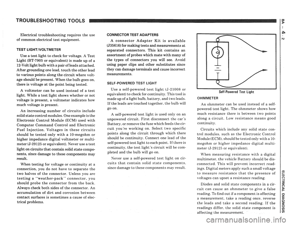
SELF-POWERED TEST LIGHT
Use a self-powered test light (5-21008 or
equivalent) to check for continuity. This tool is
made up of a light bulb, battery, and two leads.
If the leads are touched together, the bulb will
go on.
A self-powered test light is used only on an
unpowered circuit. First disconnect the car's
Battery, or remove the fuse which feeds the cir-
cuit you're working on. Select two specific
points along the circuit through which there
should be continuity. Connect one lead of the
self-powered test light to each point. If there is
continuity, the test light's circuit will be com-
pleted and the bulb will go on.
Never use a self-powered test light on cir-
cuits that contain solid state components,
since damage to these components may result. Self-Powered Test Light
OHMMETER
An ohmmeter can be used instead of a self-
powered test light. The ohmmeter shows how
much resistance there is between two points
along a circuit. Low resistance means good
continuity.
Circuits which include any solid state con-
trol modules, such as the Electronic Control
Module
(ECM), should be tested only with a 10-
megohm or higher impedance digital multi-
meter
(5-29125 or equivalent).
VIThen measuring resistance with a digital
multimeter. the vehicle Battery should be dis-
connected. This will prevent incorrect read-
ings. Digital meters apply such a small voltage
to measure resistance that the presence of
voltages can upset a resistance reading.
Diodes and solid state components in a cir-
cuit can cause an ohmmeter to give a false
reading. To find out if a component is affecting
a measurement, take a reading once, reverse
the leads and take a second reading.
If the
readings differ, the solid state component is
affecting the measurement.
Page 1209 of 1825
POWER DISTRIBUTION
CIRCUIT OPERATION
Electrical power for the car is provided by the
Generator when the engine is running. The
schematic diagram shows how each circuit gets
its power. For more details about the Gener-
ator, and connections to the Battery and
Starter, see Starter and Charging System, Sec-
tion
8A-30.
The car's Power Distribution System con-
sists of Fusible Links, Fuses, Circuit Breakers,
the Light Switch and the Ignition Switch. Fusi-
ble Links are short pieces of wire to which they
supply power. They are covered with a special
high-temperature insulation. When conducting
a high current, the Fusible Link will melt and
stop current flow. They are designed to protect
the car's electrical system from electrical
shorts where it is not protected by the Circuit
Breakers and Fuses. See Fuse Block Details
and Light Switch Details for complete wiring to
the first component in each circuit.
The Ignition Switch has six positions, five of
which have detents. The BULB TEST position
is after the RUN position and just before the
START position. BULB TEST does not have a
detent. As shown in the schematic, circuits
which are supplied from the Ignition Switch are
On (Hot) for different switch positions. Indi-
vidual schematics show their fuses supplied
from headings such as "Not In Run. "The head-
ing corresponds to the Ignition Switch position
in which power is On.