bulb PONTIAC FIERO 1988 Service Manual PDF
[x] Cancel search | Manufacturer: PONTIAC, Model Year: 1988, Model line: FIERO, Model: PONTIAC FIERO 1988Pages: 1825, PDF Size: 99.44 MB
Page 1612 of 1825
INSTRUMENT PANEL, GAGES & CONSOLE 8C-'I
SECTION 8C
NSTRUMENT PANEL, GAGES & CONSOLE
CONTENTS
General Description ................................... 8C-1
Instrument Panel and Gages ........................ 8C-1
Printed Circuit .......................................... 8C-1
Instruments ................................................... 8C- 1
Speed Sensors
............................ .. ............. 8C- 1
Pinion Gear
............................................. 8C-2
Photo Speed Sensor ................................ 8C-2
PM Generator ................... .. ...... ............... 8C-2
Speedometer ................................................ 8C-2
Mechanical ....................... .. .................... 8C-2
Quartz ........................ .. .......................... 8C-2
Digital .................... .. ...... ................. 8C-2
Fuel Gage .................................................... 8C-2
Temperature Warning Light ...................... 8C-3
Generator Warning Light ............................ 8C-3
Engine Oil Pressure Light ............................ 8C-3
"Service Engine Soon" Light ....................... 8C-3
Upshift Indicator Light .............................. 8C-3
Diagnosis .................... .. ........................... 8C-3
General Information .................................. 8C-3
Instrument Panel & Gages ...................... ..... 8C-3
On-Car Service ......................... .. ........... 8C-4
Instrument Panel Pad ................................... 8C-4
Instrument Panel Cluster ........................... 8C-4
Instrument Panel Carrier ............................. 8C-4
Headlight Switch .......................................... 8C-4
Console Mounted Switches and
Accessories
............................................... 8C-4
Console ......................................................... 8C-4
Speedometer .................................................. 8C-5
Illustra3ions ................................................. 8C-5
IP Pad ........................................................... 8C-5
IP Carrier ................................................... 8C-6
Instrument Cluster ....................................... 8C-6
Lower IP Covers ......................................... 8C-7
IP Trimplates ............................................... 8C-7
IP Hush Panels; with A/C .......................... 8C-8
..................... IP Lower Trim Pad (Console) 8C-8
Map Holder or Map Pocket ........................ 8C-8
IP Hush Panels; without A/C ..................... 8C-9
Radio Mounting ........................................... 8C-9
Subwoofer & Hatch Release
Switches/Covers ........................................ 8C- 10
Foglamp Switch/Cover ................................ 8C- 10
Oil Pressure and Temperature
Switches
..................................................... 8C-11
Heater/Ventilation/Defroster
Ductwork .................................................. 8C- 12
A/C and Defroster Ductwork ..................... 8C-13
Ram Vent System Ductwork ....................... 8C-14
Console Mounted Switches
&
Accessories ................................................. 8C- 14
Dash Insulators
............................................ 8C- 15
Heater Floor Outlet
..................................... 8C-15
................ Headlamp/Parking Lamp Switch 8C- 15
............. Dash Mounted Accessory Switches 8C- 15
GENERAL DESCRIPTION
INSTRUMENT PANEL AND GAGES
INSTRUMENTS
Instruments consist of fuel gage, temperature
The instrument panel on most cars is a sing,e unit indicator light, generator light, oil pressure indicator
design and all parts attach to the main instrument light, and speedometer. See Section 9F for optional
panel with clips and screws. To service the instrument Gages and tachometer. Service on instruments
panel and components see on-car service information, can be obtained through authorized repair stations.
However, knowledge of instrument circuit checks will
PRINTED CIRCUIT
All models are equipped with printed circuits
which supply current to most instrument panel lights
and instruments. These circuits are made of copper foil
which is die cut and bonded to a polyester base film
(usually mylar). The printed circuit electrical power is
supplied by a connector containing several wires, as
shown in the instrument panel wiring harness
installation instructions. The connector also helps
retain the printed circuit to the speedo cluster. The rest
of the circuit is retained by additional connectors (if
used) and snap-in
bulbs/sockets. For individual
printed circuit diagrams, see Section
8A-80/8 1/82/83,
'Instrument Panel'. help
in determining if operating difficulties lie in the
instrument itself or its related circuit.
Instruments have been designed for easy removal
by elimination of separate wiring. With the wiring
provisions integrated with the instrument panel wiring,
the instruments can be removed after removing the
trim and lens.
SPEED SENSORS
There are three speed sensors currently in use:
1. PINION GEAR; used in mechanical systems
2. PHOTO SPEED SENSORS; used in mechanical
systems
3. PM GENERATOR; used in electronic systems
Page 1614 of 1825
INSTRUMENT PANEL. GAGES & CONSOLE 8C-3
tank only when ignition switch is turned to "ON" or
"ACCESSORY" positions.
When ignition is turned to "OFF" or "START"
positions, the pointer may come to rest at any position.
The letters
"E" and "F" on the fuel gage are used to
point out direction of indicator travel only.
TEMPERATURE WARNING LIGHT
The engine temperature warning light is
controlled by a thermal switch which senses engine
coolant temperatures.
When the ignition switch is turned to "START"
position, a test circuit is closed and the light will come
on to indicate whether the light is functioning properly.
It is important to note that with low boiling-point
coolants (such as plain water) the temperature light
may not come on even though the coolant is boiling.
GENERATOR WARNING LIGHT
The generator warning light, located in the
instrument cluster, should come on when the ignition
switch is turned
"ON" and engine is not running. If
not, either the bulb is burned out or wiring to generator
has an open circuit.
When the generator voltage output becomes
greater than the battery voltage, the
"GEN" light
should go out. This does not, however, indicate
whether the battery is being charged or if the voltage
regulator is functioning properly.
Checks of the charging system are covered in
Section 6D, 'Engine Electrical'.
ENGINE OIL PRESSURE LIGHT
The engine oil pressure warning light is mounted
in the instrument cluster and controlled by a pressure
operated switch located on the engine block. When the ignition switch is
in the
"run" or "start9' position, the
oil pressure light should come on. If not, the bulb is
burned out, there is an open circuit between the bulb
and the oil pressure switch, or there is an open circuit
between the oil pressure switch and the choke heater.
After the engine is running, the oil pressure light
should go out when the oil pressure reaches the correct
specification. If not an oil pressure problem, a faulty oil
pressure switch or an open circuit from the choke
heater fuse to the oil pressure switch is indicated.
"SERVICE ENGINE SOON" LIGHT
All cars have a "SERVICE ENGINE SOON"
light mounted in the instrument cluster. The
"SERVICE ENGINE SOON9' light should come on
during engine starting. The light may stay on
a short
time after the engine starts.
If the light comes on while
driving, service to the emission control system may be
required. See Section
6E and Section 8A-80,
'Instrument Cluster', for complete diagnosis and
wiring diagrams of the
""P;RVICE ENGINE SOON"
light circuit.
UPSHIFT INDICATOR LIGHT
If your vehicle has a manual transmission, there
may be an
''Upshift" light on the instrument panel.
This light is illuminated to indicate optimum shift
points throughout the range from optimum fuel
economy to optimum performance. When this light is
on, shift your transmission to the next higher gear
range if conditions permit. For fuel economy,
accelerate slowly and shift when the light goes on. For
performance, accelerate as desired and shift when the
light goes on.
Safe operation of the vehicle may require shifting
differently than indicated by the "Upshift" light to
adapt to weather, road or traffic conditions.
Downshifting one or more gears may be required
to keep the engine running smoothly or to maintain
satisfactory performance.
DIAGNOSIS
Diagnostic information for all instrument panel
electrical systems is found in Section
8A-80,
'Instrument Panel'.
CAUTION: When removing or
installing any electrical units,
disconnect the negative battery cable
to prevent possible short circuits
which could lead to personal injury
and/or property damage. When
replacing a speedometer or
odometer assembly, the law requires the
odometer reading of the replacement unit to
be set to register the same mileage as the
prior odometer.
if the same mileage cannot be
set, the
law requires that the replacement
odometer be set to zero and a label be
installed on the driver's door frame to show
the previous odometer reading and the date
of replacement.
GENERAL BNFORMATlOM
INSTRUMENT PANEL AND GAGES
The instrument panel is a single unit design and
and screws. To service the instrument panel and
all parts attach to the main instrument panel with clips components see Figs. 601 through 610.
Page 1703 of 1825
2H-6 STATIONARY GLASS - F STYLE
all traces of factory installed adhesive must be
removed prior to reinstallation.
5. Wipe sanded mirror support with clean paper
towel saturated with alcohol and allow to dry.
6. Follow directions on manufacturer's kit to
prepare
rearview mirror support prior to
installation on glass.
7. Properly position support to its premarked
location, with rounded end pointed upward; press
support against glass for 30 to 60 seconds,
exerting steady pressure against glass. After five
minutes, any excess adhesive may be removed
with an alcohol moistened paper towel or glass
cleaning solution.
8. Reinstall mirror
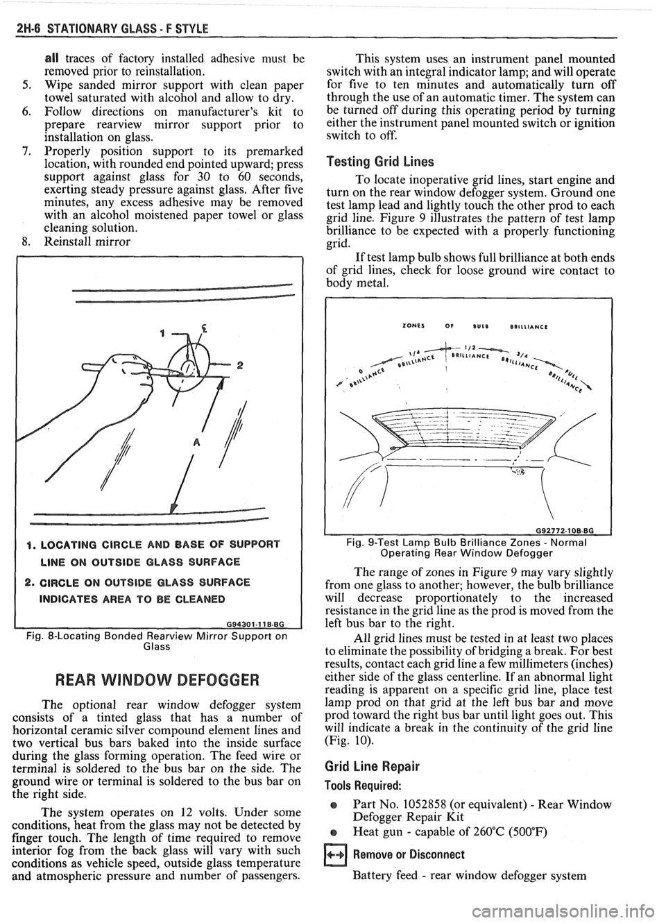
4. LOCATING CIRCLE AND BASE OF SUPPORT
LINE ON OUTSIDE GLASS SURFACE
2. CIRCLE ON OUTSIDE GLASS SURFACE
INDICATES AREA TO BE CLEANED
G94301-11 B.BG
Fig. 8-Locating Bonded earv view Mirror Support on
Glass
REAR WlMBOW DEFOGGER
The optional rear window defogger system
consists of a tinted glass that has a number of
horizontal ceramic silver compound element lines and
two vertical bus bars baked into the inside surface
during the glass forming operation. The feed wire or
terminal is soldered to the bus bar on the side. The
ground wire or terminal is soldered to the bus bar on
the right side.
The system operates on 12 volts. Under some
conditions, heat from the glass may not be detected by
finger touch. The length of time required to remove
interior fog from the back glass will vary with such
conditions as vehicle speed, outside glass temperature
and atmospheric pressure and number of passengers. This
system uses an instrument panel mounted
switch with an integral indicator lamp; and will operate
for five to ten minutes and automatically turn off
through the use of an automatic timer. The system can
be turned off during this operating period by turning
either the instrument panel mounted switch or ignition
switch to off.
Testing Grid Lines
To locate inoperative grid lines, start engine and
turn on the rear window defogger system. Ground one
test lamp lead and lightly touch the other prod to each
grid line. Figure
9 illustrates the pattern of test lamp
brilliance to be expected with a properly functioning
grid.
If test lamp bulb shows full brilliance at both ends
of grid lines, check for loose ground wire contact to
body metal.
Fig. 9-Test Lamp Bulb Brilliance Zones - Normal
Operating Rear Window Defogger
The range of zones in Figure 9 may vary slightly
from one glass to another; however, the bulb brilliance
will decrease proportionately to the increased
resistance in the grid line as the prod is moved from the
left bus bar to the right.
All grid lines must be tested in at least two places
to eliminate the possibility of bridging a break. For best
results, contact each grid line a few millimeters (inches)
either side of the glass centerline. If an abnormal light
reading is apparent on a specific grid line, place test
lamp prod on that grid at the left bus bar and move
prod toward the right bus bar until light goes out. This
will indicate a break in the continuity of the grid line
(Fig.
10).
Grid Line Repair
Tools Required:
o Part No. 1052858 (or equivalent) - Rear Window
Defogger Repair Kit
e Heat gun - capable of 260°C (500°F)
Remove or Disconnect
Battery 'feed - rear window defogger system
Page 1704 of 1825
STATIONARY GLASS - F STYLE 2W.7
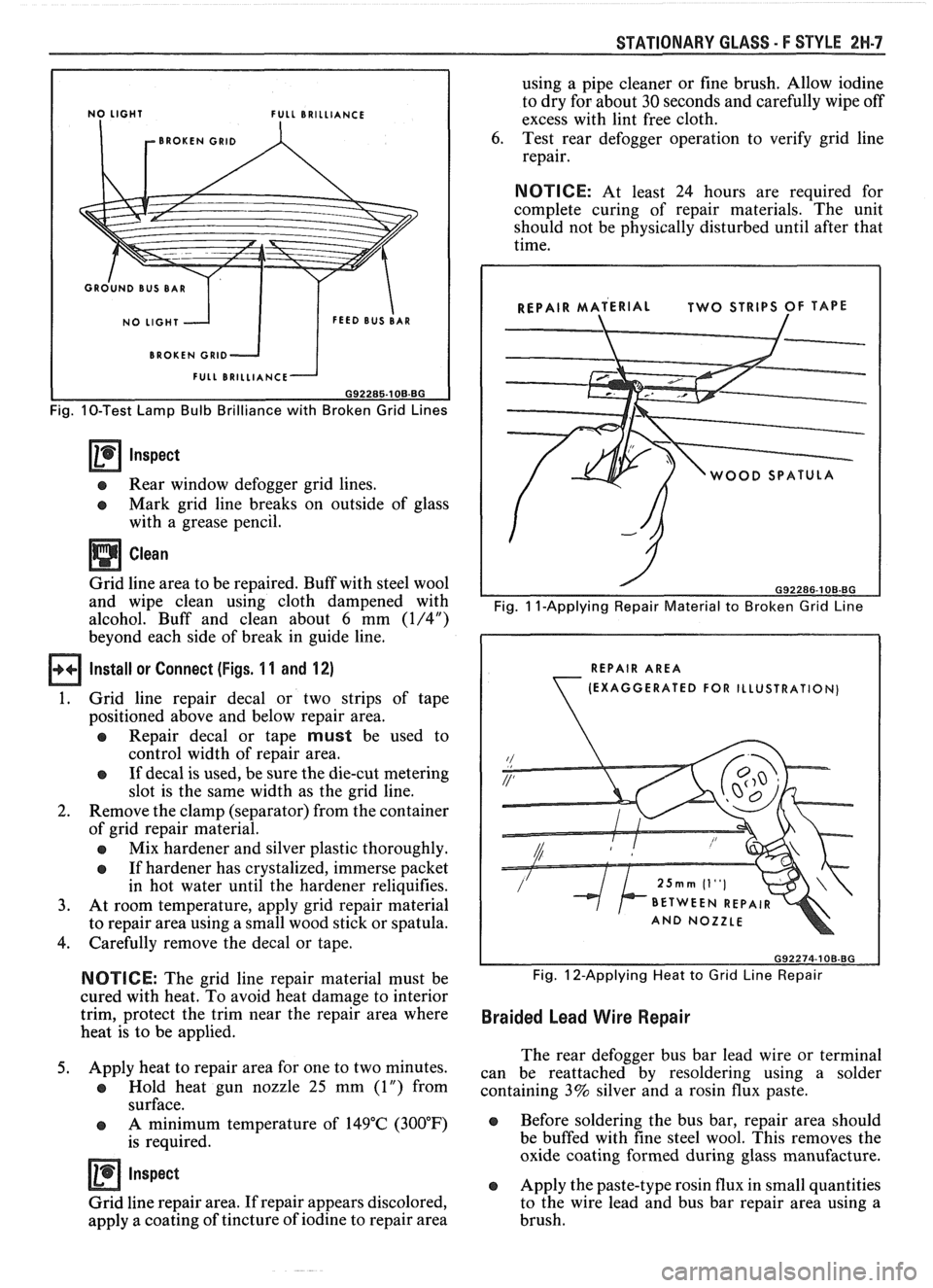
L BRILLIANCE
BROKEN
GRlD
BROKEN GRlD
Fig. 10-Test Lamp Bulb Brilliance with Broken Grid Lines
Inspect
e Rear window defogger grid lines.
e Mark grid line breaks on outside of glass
with a grease pencil.
Clean
Grid line area to be repaired. Buff with steel wool
and wipe clean using cloth dampened with
alcohol. Buff and clean about
6 mm (1/4")
beyond each side of break in guide line.
Install or Connect (Figs. 1 1 and 12)
1. Grid
line repair decal or two strips of tape
positioned above and below repair area.
a Repair decal or tape must be used to
control width of repair area.
e If decal is used, be sure the die-cut metering
slot is the same width as the grid line.
2. Remove the clamp (separator) from the container
of grid repair material.
a Mix hardener and silver plastic thoroughly.
e If hardener has crystalized, immerse packet
in hot water until the hardener reliquifies.
3. At room temperature, apply grid repair material
to repair area using a small wood stick or spatula.
4. Carefully remove the decal or tape.
NOTICE: The grid line repair material must be
cured with heat. To avoid heat damage to interior
trim, protect the trim near the repair area where
heat is to be applied.
5. Apply heat to repair area for one to two minutes.
a Hold heat gun nozzle 25 mm (1") from
surface.
e A minimum temperature of 149°C (300°F)
is required.
Inspect
Grid line repair area. If repair appears discolored,
apply a coating of tincture of iodine to repair area using
a pipe cleaner or fine brush. Allow iodine
to dry for about
30 seconds and carefully wipe off
excess with lint free cloth.
6. Test rear defogger operation to verify grid line
repair.
NOTICE: At least 24 hours are required for
complete curing of repair materials. The unit
should not be physically disturbed until after that
time.
WOOD SPATUL
Fig. 1 I-Applying Repair Material to Broken Grid Line
REPAIR AREA
(EXAGGERATED
FOR ILLUSTRATION)
Fig. 12-Applying Heat to Grid Line Repair
Braided Lead Wire Repair
The rear defogger bus bar lead wire or terminal
can be reattached by resoldering using a solder
containing 3% silver and a rosin flux paste.
e Before soldering the bus bar, repair area should
be buffed with fine steel wool. This removes the
oxide coating formed during glass manufacture.
e Apply the paste-type rosin flux in small quantities
to the wire lead and bus bar repair area using a
brush.
Page 1756 of 1825
REAR END - F STYLE 7W-13
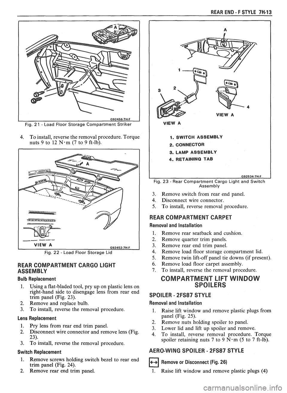
Fig. 2 1 - Load Floor Storage Compartment Striker
4. To
install, reverse the removal procedure. Torque
nuts
9 to 12 N-m (7 to 9 ft-lb).
Fig. 22 - Load Floor Storage Lid
REAR COMPARTMENT CARGO LIGHT
ASSEMBLY
Bulb Replacement
1. Using a flat-bladed tool, pry up on plastic lens on
right-hand side to disengage lens from rear end
trim panel (Fig. 23).
2. Remove and replace bulb.
3. To install, reverse the removal procedure.
Lens Replacement
1. Pry lens from rear end trim vanel.
2. Disconnect wire connector and remove lens (Fig.
23).
3. ~d install, reverse the removal procedure.
Switch Replacement
1. Remove screws holding switch bezel to rear end
trim panel (Fig. 24).
2. Remove rear end trim panel.
VlEW A
1. SWITCH ASSEMBLY
2. CONNECTOR
8. LAMP ASSEMBLY
4. RETAINING TAB
Fig. 23 - Rear Compartment Cargo Light and Switch
Assembly
3. Remove
switch from rear end panel.
4. Disconnect wire connector.
5. To
install, reverse removal procedure.
WEAR COMPARTMENT CARPET
Removal and Installation
1. Remove rear seatback and cushion.
2. Remove quarter trim panels.
3. Remove rear end trim panel.
4. Remove load floor storage compartment lid.
5. Remove twin lift-off panel tie downs (if present).
6. Remove load floor carpet assembly.
7. To install, reverse the removal procedure.
GOMPARTMEN"FLlFT WINDOW
SPOILERS
SPOILER - 2FS87 STYLE
Removal and lnstallation
1. Raise lift window and remove plastic plugs from
panel (Fig. 25).
2. Remove nuts holding spoiler to panel.
3. Lower lid
and lift up spoiler and remove.
4. To install, reverse removal procedure. Torque
spoiler retaining nuts
7 to 9 N.m (5 to 7 ft-lb).
AERO-WING SPOILER - 2FS87 STYLE
a Remove or Disconnect (Fig. 26)
1. Raise lift window and remove plastic plugs (4)
Page 1758 of 1825
WEAR END - F STYLE 7H-15
A
SECTION A-A 1. SPOILER
2. PLUG
3. NUT
4. WASHER
6. STUD 093858-7H.F
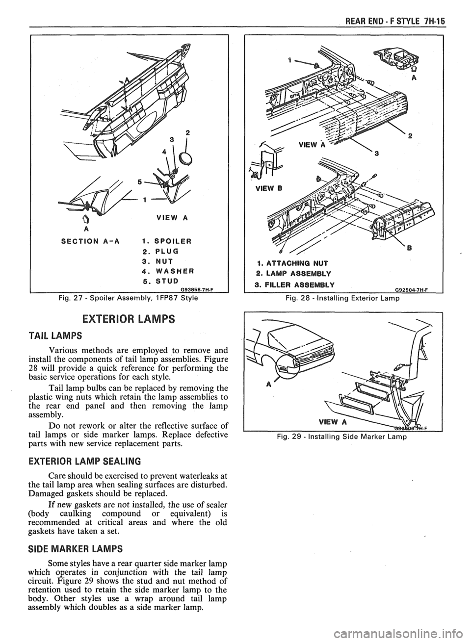
Fig. 27 - Spoiler Assembly, 1 FP87 Style
1. ATTACHING NUT
2. LAMP A98EMBLY
Fig. 28 - Installing Exterior Lamp
EXTERIOR LAMPS
TAIL LAMPS
Various methods are employed to remove and
install the components of tail lamp assemblies. Figure
28 will provide a quick reference for performing the
basic service operations for each style.
Tail lamp bulbs can be replaced by removing the
plastic wing nuts which retain the lamp assemblies to
the rear end panel and then removing the lamp
assembly.
Do not rework or alter the reflective surface of
tail lamps or side marker lamps. Replace defective
Fig. 29 - Installing Side Marker Lamp parts with new service replacement parts.
EXTERIOR LAMP SEALING
Care should be exercised to prevent waterleaks at
the tail lamp area when sealing surfaces are disturbed.
Damaged gaskets should be replaced.
If new gaskets are not installed, the use
of sealer
(body caulking compound or equivalent) is
recommended at critical areas and where the old
gaskets have taken a set.
SIDE MARKER LAMPS
Some styles have a rear quarter side marker lamp
which operates in conjunction with the tail lamp
circuit. Figure
29 shows the stud and nut method of
retention used to retain the side marker lamp to the
body. Other styles use a wrap around tail lamp
assembly which doubles as a side marker lamp.
Page 1760 of 1825
ROOF - F STYLE 8H-1
SECTION 8H
ROOF
CONTENTS
Formed Headlining .......................................... 8H- 1
Interior Roof Attachments
.............................. 8H- 1
Interior Garnish Moldings .............................. 8H-2
Exterior Roof Moldings and
Attachments
.................................... .... ... 8H-3
Twin Lift-off Panel
......................................... 8H-3
Convertible Top
Top Operation
............................................ 8H-7
Header Inner Garnish
................................. 8H-8
"A" Pillar Inner Garnish
........... .;. .............. 8H-9
Header
"A" Pillar Seal ................................ 8H-9
Side Rail Seal and Retainer
......................... 8H-9
Main Pillar Seal and Retainer
..................... 8H-9
No.
5 Bow Seal .......................................... 8H-9
No. 1 Bow Garnish Molding
....................... 8H-9
Top Cover Assembly
.................................... 8H- 1 1
Side Stay Pads ............................................. 8H-13
Rear Stay Pads ............................................ 8H- 13
No.
1 and No. 2 Bows ................................. 8H- 13 NO. 3
BOW
.................................................... 8H-15
NO. 4 BOW ................................................ 8H-15
NO. 5 BOW ................................................. 8H-15
Top Stack Assembly Complete .................... 8H- 16
Quarter Inner Upper Trim Cap
.................. 8H- 17
Quarter Trim Panel
.................................... 8H- 17
Quarter Cap Belt Molding
........................... 8H- 17
Tonneau Panel Latch
................................. 8H- 17
Tonneau Release Solenoid
........................... 8H- 17
No. 5 Bow Release Handle
.......................... 8H- 19
No.
5 Bow Latch ....................................... 8H-19
Tonneau Panel
.......................................... 8H- 19
Tonneau Panel Seal
............................. ......... 8H-20
Deck Lid Spoiler ........................................ 8H-2 1
Center High Mount Stop Lamp .................. 8H-21
Deck Lid .................................................... 8H-21
Deck Lid Panel Seal
................................. 8H-22
Door Cap Belt Molding ............................... 8H-22
Front Belt Retractor Assembly ................... 8H-22
FORMED HEADLINING 1. Load the headlining through the rear
The one-piece formed headlining (Fig. 1) consists
of a molded fiberglass substrate covered with a foam
and cloth facing. The one-piece construction requires
the headlining be serviced as a complete assembly.
The headlining is held partially in place by
retaining fasteners located in the headlining which fit
into slots in the roof panel. Final attachment is
accomplished when the interior moldings and
attaching screws that retain the sunshade brackets,
dome lamp base and coat hooks are installed.
Removal
1. Remove the following items:
e Back body opening upper garnish molding
r Windshield side upper garnish molding (1,
Fig. 3 or
6)
e Rear vertical garnish molding
a Windshield header courtesy reading and
console lamp
e Sunshades
e Partially remove shoulder belt bezel and
belt
a Coat hooks and rail panel inserts
2. Grasp headlining assembly with both hands at
outer edges and move to the right of centerline to
disengage fastener assemblies from front
attaching slots.
3. Remove headlining assembly through right front
door.
lnstallation
Care must be exercised when loading assembly.
Excessive flexing may result in damage. compartment
opening.
2. Align headlining with cutouts for sunshades and
dome lamp and install sunshade brackets and
dome lamp base. Do not tighten sunshade bracket
and dome lamp attaching retainers completely
until headlining is aligned properly at all
hardware attaching locations.
3. Align headlining to roof inner panel with
fasteners positioned over holes in roof panel and
using palm of hand, push up on headlining at
fastener locations.
4. Install all previously removed hardware and
interior moldings.
INTERIOR ROOF ATTACHMENTS
DOME LAMPS
The dome lamp operates in conjunction with the
door jamb switch and/or the
headlamp switch. The
dome lamp harness extends up the right windshield
pillar, outboard of the sunshade support and across the
roof inner panel to the dome lamp.
Removal and Installation (Typical)
1. Grasp lens portion of dome lamp assembly,
squeeze and pull down to remove.
2. Remove bulb from terminal clips.
3. Remove retainers from studs.
4. Disengage wire harness from lamp housing and
remove dome lamp housing.
5. To install dome lamp assembly, reverse removal
procedure.
Page 1817 of 1825
2 - CHASSIS INDEX
Backup Lamp Switch (Circuit) .......... 8A- 1 12. 7A 1-5
Backup Lights
..................................................... 8B-1
...................................................... Battery Section 6D 1
............................ Battery Specification Chart 6D 1-7
.................................... Body Identification ... .... OA- 1
Borg Warner Rear Axle .......................... Section 4B1
...................................................... Blower Motor 1A-14
Blower Switch
.................................................... 1 A- 13
Booster Assembly
............................................. 5D2-2
Brakes
- General ......................................... Section 5
Adjustment
.................................................... 5C3-4
Booster Assembly
. Tandem
Diaphragm
................... .... ..................... 5D2- 1
................................................ Components 5C3- 1
Diagnosis and Inspection
................................. 5-3
Disc Brake Caliper Assembly
.................................................... 3548 Series 5B6-1
Drum Brake Assembly ........................ Section 5C3
General Description
.......................................... 5-2
On-Car Service
.................................................... 5-7
Specifications & Special Tools ......................... .5 F. 1
...................................................... Unit Repair 5A3- 1
.......................................... Warning System 8A-4 1-0
............ Brake Pedal Mounting .. ......................... 5-1 7
Bulb Usage Chart
............................................ 8B-10
............................................ Bumpers Section 2B,3 D.6
Bumper Energy Absorbing Units
.................... 2B-2
Bench Testing
................................................ 2B-3
........................................ Damage/Leakage 2B-3
................................ Removal After Collision 2B-2
............................................. Fascia Rub Strips .2 B. 1
.................................................... Front Bumper 2B-2
Assembly
........................................................ 2B-4
Energy Absorber
........................................... 2B-4
............................................................. Fascia .2 B. 1
On-Vehicle Service
...................................... 2B-4
Rear Bumper
.................................... .... ............ 2B-2
........................................................ Assembly 2B-5
Energy Absorber
............................................ 2B-4
............. .................... Fascia Molding Strip .. 2B-5 ........................................... Service Procedures .2 B. 1
.................................................. Specifications 2B-5
C
Caliper Assembly . Disc Brake
.............................................. 3000/3 100 Series 5B 1-2
3548 Series
...................................................... 5B6-2
Caliper Overhaul
....................... 3000/3 100 Series .. ............... 5B 1-4
3548 Series
.................................................... 5B6-5
Caster and Camber Adjustment
........................ 3A- 1
............................................. Catalytic Converter 6F-2
Center High-Mounted Stoplight
....................... ... 8B- 1
Charging System
...................... 8A.30.7, Section 6D3
Chassis Electrical
.................................... Section 8B
Center High Mounted Stoplight
...................... 8B-1 ................................. Exterior Light Monitor .8 B. 1
................................................................ Chimes 8A-77
................................ Cigar Lighter (Circuit) 8A- 1
14-0
.............................. Circuit Breaker Details Section 8A
Power ACC Circuit Breaker .... 8A- 10.1.10.3.10.5.
11-3
.... Window Circuit Breaker 8A~10~1,10~3.10~5.1 1.4
Clutch
........................................................ Section 7C
......................................... General Description .7 C. 1 ........................................................... Diagnosis 7C-2 Bleeding
Hydraulic Clutch System
................. .7 C.2
Preliminary Checks ..................................... ... 7C-2
On-Vehicle Service
........................................... 7C-5
Clutch Hydraulic System
.................................. 7C-5
Clutch Pedal ...................................................... 7C-6
Pilot Bearing
..................................................... 7C-6
Pressure Plate and Disc
.................................... 7C-6
Special Tools
......................... ....... ................ 7C-8
Specifications
................................................... 7C-8
Coil Springs and Insulators .............................. 3D-1
Component Fluid Capacities
................................ OB-6
Component Location Views
........................ 8A-201-0
Composite Master Cylinder
................... Section 5A3
Compression Test
.................. .. ............................. 6-5
Condenser Mounting
....................................... 1B 1-24
Connectors
.................................................... 8A-202-0
Coolant Fan Temperature Switch
...................... 8A-3 1
Cooling and Radiator
................................ Section 6B
Cooling System Capacities
................................. OB-6
Cooling System Diagnosis
.................................... 6B-3
Cranking System
...................................... Section 6P*
Diagnosis ..................................................... 6~2
General Description ................................ 6D2- 1
Cranking System
........................................ 6D2- 1
Solenoid
................................................... 6D2- 1
Starter Motor ......................................... 6D2-1
On-Vehcile Service
...................................... 6D2-4
Specifications
............................................ 6D2- 1
Starter
........................................................ 6D2-4
Unit Repair
............................................ 6D2-6- 11
Service Procedures
...................................... 6D2-3
Cruise Control
.............................. 8A-34-0, Section 9B
Diagnosis
............................................................ 9B-4
Cruise Set Speed High or Low
.................... 9B-4
Cruise System Surges
.................................. 9B-4
Cruise Tap-Up and Tap-Down
...................... 9B-4
Excessive Cruise Speed Loss on
Hills
........................................................... 9B-4
General Description
........................................ 9B-1
Electrical and Vacuum Release
Switches
...................................................... 9B-4
Electrical Harness
.......................................... 9B-A
Electronic Controller (Module) .................... 9B .
Off/On/Resume/Accel Switch
Operation
.................................................. .91 B-
Servo Unit
.................................................... 9B-2
Set/Coast Button Switch .............................. 9B-1
................................................ Speed Sensors 9B-3
Vacuum Supply
............................................ 9B-4
On-Car Service
.................................................. 9B-6
................................ Cruise Release Switches 9B-6
.......................................... Servo Mounting 9B-10
Vacuum Harness and Cable Routing
VIN
E ................................. .. .................. 9B,7
.................................................... VIN F, 8 9B-9
....................................................... VIN S 9B-8
........................ Vacuum Tank - VIN S,F,E, 9B-10
.............................. Cruise Control (Circuit) 8A-34-0
D
......................................... Defogger (Circuit) $A-6 1-0
..................... ...... Defroster Duct Assembly ... .812 C-
Diagnosis
Air Conditioning
- General ........................... 1B-5
.................... Automatic Transmission - General 7A
Automatic Transmission
- ................ HD-700-R4-2
Page 1821 of 1825
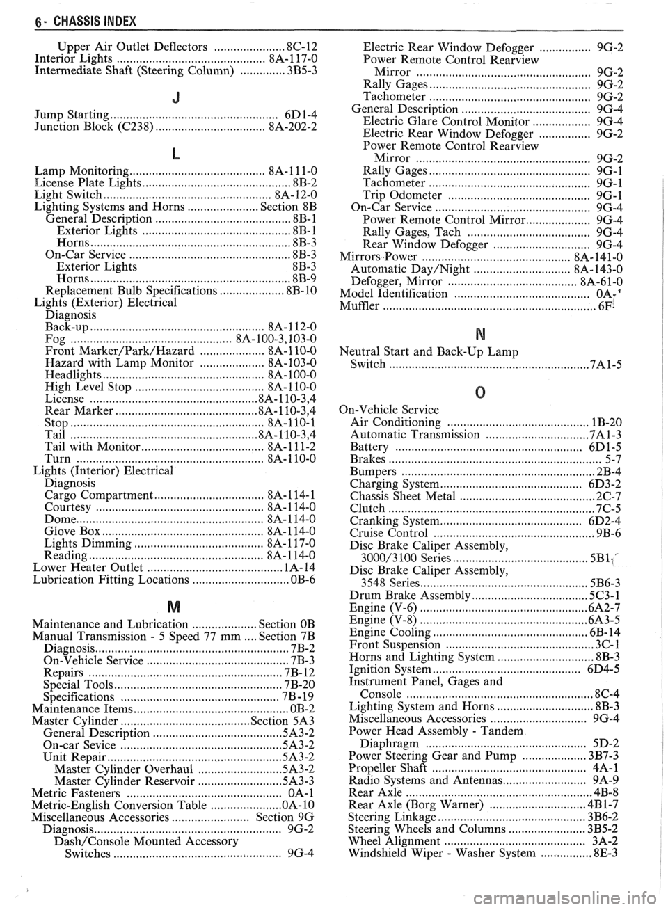
6- CHASSIS INDEX
Upper Air Outlet Deflectors ...................... 8C-12
Interior Lights ............................................. 8A- 1 17-0
Intermediate Shaft (Steering Column)
.............. 3B5-3
J
Jump Starting .................................................... 6D 1-4
Junction Block
((2238) ................................. 8A-202-2
L
Lamp Monitoring ......................................... 8A- 1 1 1-0
License Plate Lights .............................................. 8B-2
Light Switch
.................................................... 8A- 12-0
Lighting Systems and Horns
...................... Section 8B
General Description ......................................... .8 B- 1
Exterior Lights
............................................ 8B- 1
Horns ....................... .. ................................. 8B-3
On-Car Service
.................................................. 8B-3
Exterior Lights 8B-3
Horns
.............................................................. 8B-9
Replacement Bulb Specifications .................... 8B-10
Lights (Exterior) Electrical Diagnosis
Back-up
...................................................... 8A- 1 12-0
Fog ............................................... 8A- 100.3,10 3.0
Front
Marker/Park/Hazard .................... 8A-110-0
Hazard with Lamp Monitor .................... 8A-103-0
Headlights .................................................. 8A- 100-0
High Level Stop
..................................... 8A-110-0
License .................................................. .8A.110.3, 4
Rear Marker
........................................... .8 A. 1 10.3, 4
Stop ........................................................... 8A-110-1
Tail ......................................................... .8 A. 1 10.3, 4
Tail with Monitor
................ .... ........... 8A- 1 1 1-2
Turn
......................................................... 8A- 1 10-0
Lights (Interior) Electrical
Diagnosis Cargo Compartment
............................. 8A- 1 14- 1
Courtesy
................................................. 8A- 1 14-0
Dome
.................................. .. ...................... 8A- 1 14-0
Glove Box .................................................. 8A- 1 14-0
Lights Dimming
...................................... 8A- 1 17-0
Reading
...................................................... 8A- 1 14-0
Lower Heater Outlet
........................................ 1A-14
Lubrication Fitting Locations .............................. OB-6
M
Maintenance and Lubrication .................... Section OB
Manual Transmission
. 5 Speed 77 mm .... Section 7B
Diagnosis
........... .. ............................................ 7B-2
On-Vehicle Service
.......................................... 7B-3
Repairs
................................... .... .................... 7B- 12
Special Tools
................................................. 7B-20
. Specifications .............................................. 7B 19
Maintenance Items
................................................ OB-2
Master Cylinder
........................................ Section 5A3
General Description
...................................... ..5A 3.2
On-car Sevice
................................................ 5A3-2
Unit Repair ..................................................... .5A 3.2
Master Cylinder Overhaul
......................... .5A 3.2
Master Cylinder Reservoir
......................... .5A 3.3
Metric Fasteners
................................................ OA- 1
Metric-English Conversion Table ..................... .O A. 10
Miscellaneous Accessories
........................ Section 9G
Diagnosis
.......................................................... 9G-2
Dash/Console Mounted Accessory
Switches
.................................................... 9G-4 Electric
Rear Window Defogger
................ 9G-2
Power Remote Control
Rearview
......................... Mirror ...................... .. 9G-2
Rally Gages
................................................. 9G-2
Tachometer
.................................................. 9G-2
..................................... General Description 9G-4
Electric Glare Control Monitor
.................. 9G-4
Electric Rear Window Defogger
................ 9G-2
Power Remote Control
Rearview
Mirror ..................................................... 9G-2
Rally Gages
................................................. 9G-1
Tachometer
................................................. 9G-1
Trip Odometer
............................................ 9G-1
............................................. On-Car Service 9G-4
Power Remote Control Mirror
.................... 9G-4
Rally Gages. Tach
..................................... 9G-4
Rear Window Defogger
.............................. 9G-4
Mirrors..Power ............................................ 8A- 141-0
Automatic
Day/Night ............................. 8A- 143-0
..................................... Defogger. Mirror 8A-61-0
.......................................... Model Identification OA-'
Muffler ................................................................. 6Fi
N
Neutral Start and Back-Up Lamp
Switch
...................................... ..
0
On-Vehicle Service
Air Conditioning
.................................... ... . 1B-20
Automatic Transmission
............................... .7A 1.3
Battery
........................................................ 6D1-5
................................ ......................... Brakes ... 5-7
Bumpers
......................................................... 2B-4
Charging System
.............................. ... ........... 6D3-2
Chassis Sheet Metal
.......................................... 2C-7
Clutch
................................................................ 7C-5
Cranking System
............................................ 6D2-4
Cruise Control ............................................... 9B-6
Disc Brake Caliper Assembly,
3000/3 100 Series .......................................... 5BliC
Disc Brake Caliper Assembly,
3548 Series
................................................... 5B6-3
Drum Brake Assembly .................................... 5C3-1
Engine (V-6) .................................................... 6A2-7
Engine (V-8) ................................................ -6A3-5
Engine Cooling ....................................... .. .... 6B- 14
Front Suspension
........................................... 3C-1
Horns and Lighting System .............................. 8B-3
Ignition System
.............................................. 6D4-5
Instrument Panel, Gages and
Console
.......................................................... 8C-4
Lighting System and Horns
.......................... .... 8B-3
Miscellaneous Accessories
.......................... .... 9G-4
Power Head Assembly
. Tandem
Diaphragm
................................................. 5D-2
Power Steering Gear and Pump
.................... 3B7-3
Propeller Shaft
............................................. 4A-1
.......................... Radio Systems and Antennas 9A-9
Rear Axle
.......................................................... 4B-8
Rear Axle (Borg Warner)
........................... ... 4B 1-7
Steering Linkage ............................................. 3B6-2
........................ Steering Wheels and Columns 3B5-2
Wheel Alignment
......................................... 3A-2
Windshield Wiper
- Washer System ................ 8E-3
Page 1823 of 1825
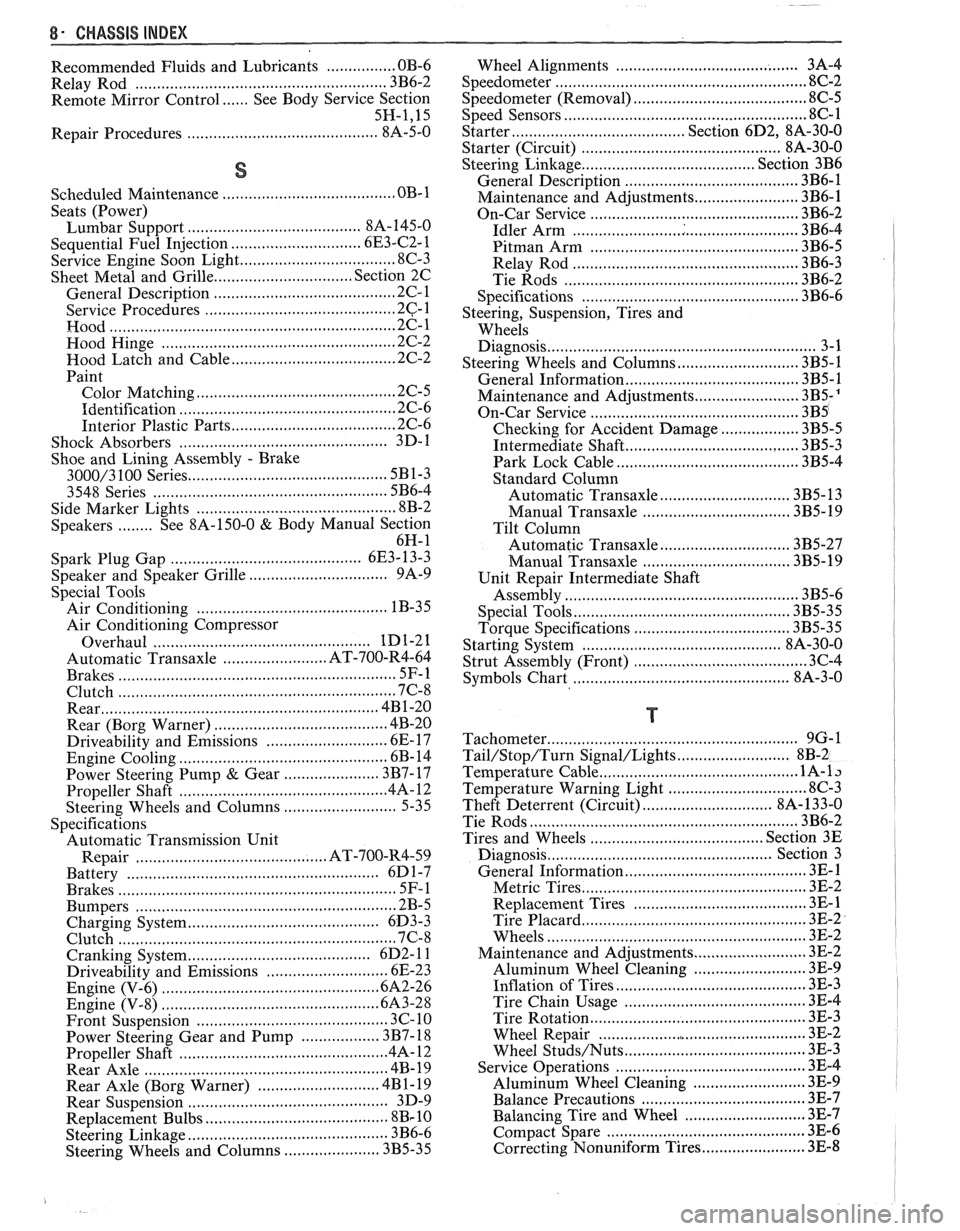
8- CHASSIS INDEX
Recommended Fluids and Lubricants ................ OB-6
Relay Rod
......................................................... 3B6-2
Remote Mirror Control
...... See Body Service Section
5H.1. 15
Repair Procedures
.......................................... 88-50
S
........................................ Scheduled Maintenance OB- 1
Seats (Power) ....................................... Lumbar Support 8A- 145-0
............................. Sequential Fuel Injection 6E3-C2- 1
Service Engine Soon Light
.................................... 8C-3
Sheet Metal and Grille
................................ Section 2C
......................................... General Description .2 C. 1
........................................... Service Procedures .2 C. 1
................................................................. Hood .2 C. 1
...................................................... Hood Hinge 2C-2
Hood Latch and Cable
...................................... 2C-2
Paint
.............................................. Color Matching 2C-5
................................................ Identification -32-6
Interior Plastic Parts ...................................... 2C-6
................................................ Shock Absorbers 3D-
1
Shoe and Lining Assembly
. Brake
............................................ 3000/3 100 Series 5B1-3
3548 Series ...................................................... 5B6-4
Side Marker Lights
.............................................. 8B-2
........ Speakers See 8A- 150-0 & Body
Manual Section
6H- 1
.................... Spark Plug Gap .. .................. 6E3-13-3
................................ Speaker and Speaker Grille 9A-9
Special Tools
............................................ Air Conditioning 1 B-3 5
Air Conditioning Compressor
................................................. Overhaul 1D1-21
........................ Automatic Transaxle AT-700-R4-64
................................................................ Brakes SF-1
Clutch ................................................................ 7C-8
................................................................ Rear 4B1-20
....................................... Rear (Borg Warner) 4B-20
........................... Driveability and Emissions .6 E. 17
................................................ Engine Cooling 6B- 14
Power Steering Pump
& Gear ...................... 3B7-17
............................................... Propeller Shaft .4 A. 12
Steering Wheels and Columns
.......................... 5-35
Specifications Automatic Transmission Unit
............................................ Repair AT-700-R4-59
..................................................... Battery 6D 1-7
................................................................ Brakes 5F-1
Bumpers
......................................................... 2B-5
Charging System
................ .. ................... 6D3-3
.............................................................. Clutch .7 (2.8
....................................... Cranking System 6D2- 1 1
Driveability and Emissions ............................ 6E-23
................................................ Engine (V-6) ..6A 2.26
Engine (V-8) .................................................. 683-28
........................................ Front Suspension 3C- 10
Power Steering Gear and Pump
.................. 3B7-18 ............................................. Propeller Shaft .4 A. 12 ........................................................ Rear Axle 4B-19 ............................ Rear Axle (Borg Warner) 4B 1- 19
Rear Suspension
.............................................. 3D-9
.......................................... Replacement Bulbs 8Br 10 .............................................. Steering Linkage 3B6-6
Steering Wheels and Columns
...................... 3B5-35
........................................ Wheel Alignments 3A-4
....................................................... Speedometer 8C-2
........................................ Speedometer (Removal) 8C-5
...................................................... Speed Sensors 8C-1
Starter ........................................ Section 6D2. 8A-30-0
............................................. Starter (Circuit) 8A-30-0
Steering Linkage ...................................... Section 3B6
....................................... General Description 3B6-1
........................ Maintenance and Adjustments 3B6-1
................................................ On-Car Service 3B6-2
..................................................... Idler Arm 3B6-4
................................................ Pitman Arm 3B6-5
.................................................... Relay Rod 3B6-3
Tie Rods
...................................................... 3B6-2
.................................................. Specifications 3B6-6
Steering, Suspension, Tires and
Wheels Diagnosis
............................................................. 3-1
Steering Wheels and Columns
............................ 3B5-1
..................................... General Information 3B5- 1
Maintenance and Adjustments
...................... 3B5-'
On-Car Service .............................. .. ........... 3B5
Checking for Accident Damage
.................. 3B5-5
Intermediate Shaft ............... .. .................... 3B5-3
Park Lock Cable .......................................... 3B5-4
Standard Column
............................. Automatic Transaxle 3B5-13
Manual Transaxle ................................. 3B5- 19
Tilt Column
.............................. Automatic Transaxle 3B5-27
.................................. Manual Transaxle 3B5-19
Unit Repair Intermediate Shaft
...................................................... Assembly 3B5-6
................................................. Special Tools 3B5-35
Torque Specifications
.................................... 3B5-35
............................................. Starting System 8A-30-0
........................................ Strut Assembly (Front) 3C-4
.................................... ..... Symbols Chart ... 8A-3-0
T
.......................................................... Tachometer 9G-1
Tail/Stop/Turn Signal/Lights .......................... 8B-2
Temperature Cable
.............................................. 112 A-
Temperature Warning Light ................................ 8C-3
Theft Deterrent (Circuit)
.............................. 8A-133-0
Tie Rods
.............................................................. 3B6-2
Tires and Wheels
........................................ Section 3E
Diagnosis
.................................................. Section 3
General Information
......................................... 3E-1
................................................... Metric Tires 3E-2
....................................... Replacement Tires .31 E-
.................................................... Tire Placard 3E-2
........................................................... Wheels 3E-2
Maintenance and Adjustments
.......................... 3E-2
.......................... Aluminum Wheel Cleaning 3E-9
............................. ......... Inflation of Tires .. 3E-3
........................................ Tire Chain Usage 3E-4
.................................................. Tire Rotation 3E-3
.............................................. Wheel Repair 3E-2
...................................... Wheel Studs/Nuts 3E-3
........................................... Service Operations 3E-4
........................ Aluminum Wheel Cleaning 3E-9
.................................... Balance Precautions 3E-7
............................ Balancing Tire and Wheel 3E-7
.............................................. Compact Spare 3E-6
........................ Correcting Nonuniform Tires 3E-8