bulb PONTIAC FIERO 1988 Service Owner's Guide
[x] Cancel search | Manufacturer: PONTIAC, Model Year: 1988, Model line: FIERO, Model: PONTIAC FIERO 1988Pages: 1825, PDF Size: 99.44 MB
Page 1408 of 1825
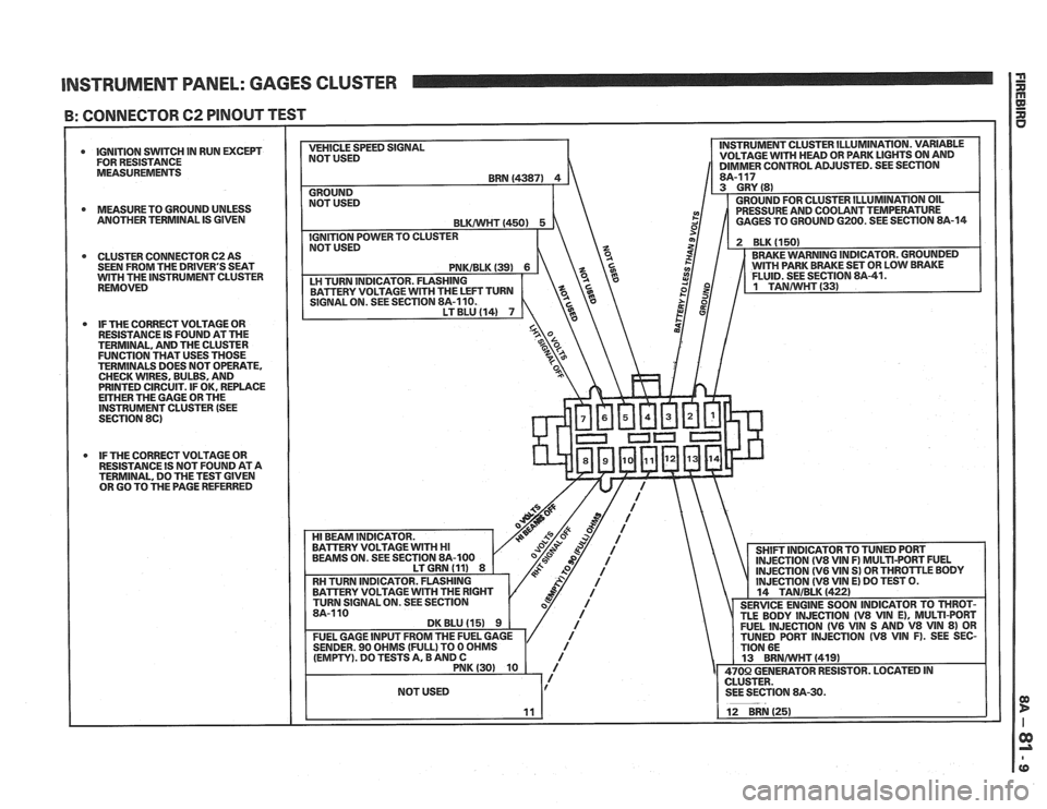
INSTRUMENT PANEL: GAGES CLUSTER I i
B: CONNECTOR 62 PINOUT TEST
0 IGNITION SWITCH IN RUN EXCEPT
FOR RESISTANCE
MEASUREMENTS
0 MEASURETO GROUND UNLESS
ANOTHER TERMINAL IS GIVEN
0 CLUSTER CONNECTOR 62 AS
SEEN FROM THE DRIVER'S SEAT
WlTH THE INSTRUMENT CLUSTER
REMOVED
IF THE CORRECT VOLTAGE OR
RESISTANCE IS FOUND AT THE
TERMINAL, AND THE CLUSTER
FUNCTION THAT USES THOSE
TERMINALS DOES NOT OPERATE.
CHECK WIRES, BULBS, AND
PRINTED CIRCUIT. IF OK. REPLACE
EITHER THE GAGE OR THE INSTRUMENT CLUSTER (SEE
SECTION 86)
IF THE CORRECT VOLTAGE OR
RESISTANCE IS NOT FOUND AT A TERMINAL, DO THE TEST GIVEN
OR GO TO THE PAGE REFERRED VEHICLE
SPEED SIGNAL
NOT USED INSTRUMENT
CLUSTER ILLUMINATION. VARIABLE
VOLTAGE
WlTH HEAD OR PARK LIGHTS ON AND 11 DIMMER CONTROL ADJUSTED. SEE SECTION I
Page 1411 of 1825
(Continued from previous page)
If the Speedometer reads correctly, refer to
Vehicle Speed Sensor, Section
8A-33 for fur-
ther diagnosis.
If the Speedometer reads incorrectly, check
LT GRN (537) wire and the Instrument Clus-
ter Printed Circuit for opens. Replace the
Speedometer Assembly if the wire and
Printed Circuit are good (see Section
8C).
O: UPSHIFT INDICATOR WIRE TEST
Disconnect ECM connector C207. Put the Igni-
tion Switch in RUN and measure the voltage at
terminal
H (see section 8A-21 or 22).
If battery voltage is present, see section
6E
for ECM diagnosis.
If battery voltage is not present, check the
TANIBLK (422) wire for an open or short to
Ground.
CIRCUIT OPERATION
The operation of an indicator is explained in
the operation of the circuit it is apart of. See the
circuit referred to for a complete description of
that indicator and the other components that
work with it. Only the gages and indicators that
do not appear in other schematics are described
in this section.
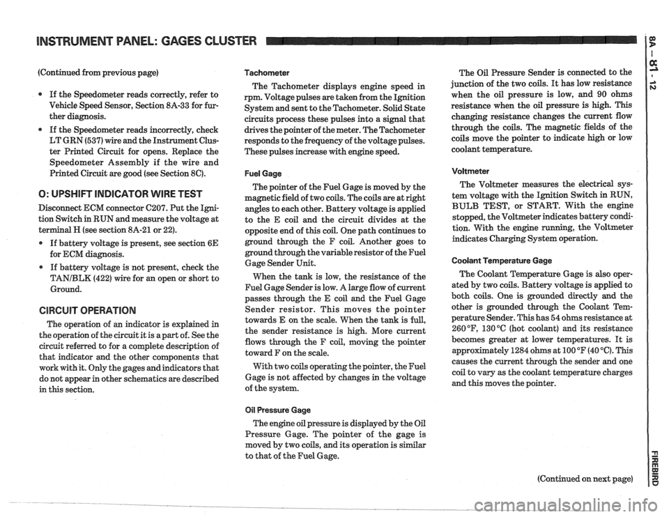
Tachometer
The Tachometer displays engine speed in
rpm. Voltage pulses are taken from the Ignition
System and sent to the Tachometer. Solid State
circuits process these pulses into a signal that
drives the pointer of the meter. The Tachometer
responds to the frequency of the voltage pulses.
These pulses increase with engine speed.
Fuel Gage
The pointer of the Fuel Gage is moved by the
magnetic field of two coils. The coils are at right
angles to each other. Battery voltage is applied
to the E coil and the circuit divides at the
opposite end of this coil. One path continues to
ground through the F coil. Another goes to
ground through the variable resistor of the Fuel
Gage Sender Unit.
When the tank is low, the resistance of the
Fuel Gage Sender is low. A large flow of current
passes through the E coil and the Fuel Gage
Sender resistor. This moves the pointer
towards E on the scale. When the tank is
full,
the sender resistance is high. More current
flows through the F coil, moving the pointer
toward F on the scale.
With two coils operating the pointer, the Fuel
Gage is not affected by changes in the voltage
of the system.
011 Pressure Gage
The engine oil pressure is displayed by the Oil
Pressure Gage. The pointer of the gage is
moved by two coils, and its operation is similar
to that of the Fuel Gage. The
Oil Pressure Sender is connected to the
junction of the two coils.
It has low resistance
when the oil pressure is low, and 90 ohms
resistance when the oil pressure is high. This
changing resistance changes the current flow
through the coils. The magnetic fields of the
coils move the pointer to indicate high or low
coolant temperature.
Voltmeter
The Voltmeter measures the electrical sys-
tem voltage with the Ignition Switch in RUN,
BULB TEST, or START. With the engine
stopped, the Voltmeter indicates battery condi-
tion. With the engine
running, the Voltmeter
indicates Charging System operation.
Coolant Temperature Gage
The Coolant Temperature Gage is also oper-
ated by two coils. Battery voltage is applied to
both coils. One is grounded directly
and the
other is grounded through the Coolant Tem-
perature Sender. This has 54 ohms resistance at
260
OF, 130 "C (hot coolant) and its resistance
becomes greater at lower temperatures. It is
appr~ximately 1284 ohms at 100 OF (40 '6). This
causes the current through the sender and one
coil to vary as the coolant temperature charges
and this moves the pointer.
Page 1412 of 1825
INSTRUMENT PANEL: GAGES CLUSTER
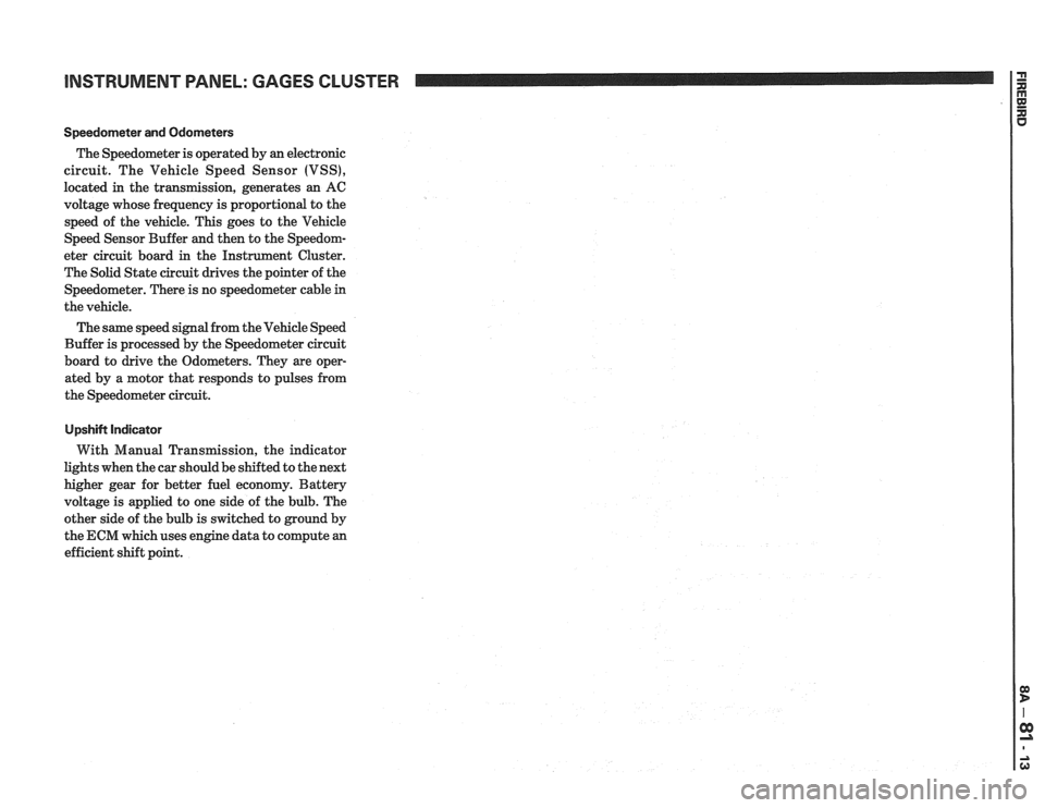
Speedorneter and Odometers
The Speedometer is operated by an electronic
circuit. The Vehicle Speed Sensor (VSS),
located in the transmission, generates an AC
voltage whose frequency is proportional to the
speed of the vehicle. This goes to the Vehicle
Speed Sensor Buffer and then to the Speedom-
eter circuit board in the Instrument Cluster.
The Solid State circuit drives the pointer of the
Speedometer. There is no speedometer cable
in
the vehicle.
The same speed signal from the Vehicle Speed
Buffer is processed by the Speedometer circuit
board to drive the Odometers. They are oper-
ated by a motor that responds to pulses from
the Speedometer circuit.
UpshiN Indicator
With Manual Transmission, the indicator
lights when the car should be shifted to the next
higher gear for better fuel economy. Battery
voltage is applied to one side of the bulb. The
other side of the bulb is switched to ground by
the ECM which uses engine data to compute an
efficient shift point.
Page 1419 of 1825
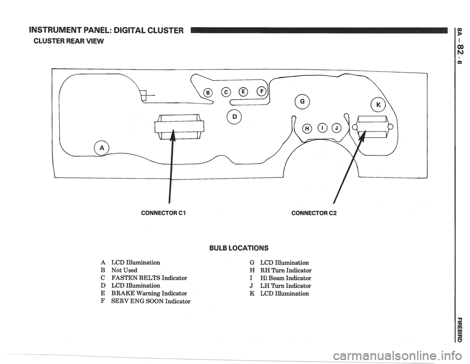
[NSTRUMENT WNEL: DIGITAL CLUSTER
CLUSTER REAR VlEW
CONNECTOR 61 CONNECTOR 62
BULB LOCATIONS
A LCD Illurnination
B Not Used
C FASTEN BELTS Indicator
D LCD Illumination
E BRAKE Warning Indicator
F SERV ENG SOON Indicator G
LCD Illumination
Indicator
Indicator
Indicator
K LCD Illumination
Page 1424 of 1825
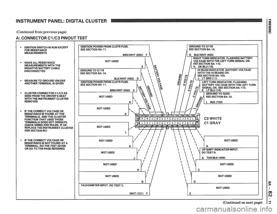
INSTRUMENT PANEL: DIGITAL CLUSTER
(Continued from previous page)
A: CONNECTOR C1 163 PINOUT TEST
IGNITION SWITCH IN RUN EXCEPT
FOR RESISTANCE
MEASUREMENTS
* MAKE ALL RESISTANCE
MEASUREMENTS WITH THE
NEGATIVE BAmERV CABLE
DISCONNECTED
4 MEASURETO GROUND UNLESS
ANOTHER TERMlNAL IS GIVEN
CLUSTER CONNECTOR
C11C3 AS - - - - . -. . - - . . . . - - . - . . - . . - - . . - SEEN FROM THE DRIVER'S SEAT WITH THE INSTRUMENT CLUSTER
REMOVED
* IF THE CORRECT VOLTAGE OR
RESISTANCE IS FOUND AT THE
TERMINALS, AND THE CLUSTER
FUNCTION THAT USES THOSE
TERMINALS DOES NOT OPERATE,
CHECK WIRES AND BULBS. IF OK,
REPLACE THEINSTRUMENT CLUSTER
(SEE SECTION 8C)
IF THE CORRECT VOLTAGE OR
RESISTANCE IS NOT FOUND AT A
TERMINAL, DO THE TEST GIVEN
OR GO TO
TI-IE PAGE REFERRED
NOT USED
(Continued on next page)
Page 1425 of 1825
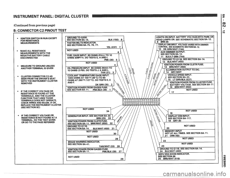
INSTRUMENT PANEL: DIGITAL CLUSTER
(Continued from previous page)
B: CONNECTOR 62 PINOUT TEST I I
IGNITION SWITCH IN RUN EXCEPT
FOR RESISTANCE
MEASUREMENTS
MAKE ALL RESISTANCE
MEASUREMENTS
WITH THE
NEGATIVE BATTERY CABLE
DISCONNECTED
MEASURETO GROUND UNLESS
ANOTHER TERMINAL IS
GIVEN
CLUSTER CONNECTOR C2 AS
SEEN FROM THE DRIVER'S SEAT
GH THE INSTRUMENT CLUSTER
REMOVED
IF THE CORRECT VOLTAGE OR
RESISTANCE IS FOUND AT THE
TERMINALS, AND THE CLUSTER
FUNCTION THAT USES THOSE
TERMINALS DOES NOT OPERATE,
CHECK WIRES AND BULBS. IF OK,
REPLACE THE INSTRUMENT CLUSTER
(SEE SECTION
86)
IF THE CORRECT VOLTAGE OR
RESISTANCE IS NOT FOUND AT A
TERMINAL, DO THE TEST GIVEN
OR GO TO THE PAGE REFERRED SEE
SECTIONS 8A-75.76,
NOT USED
ES. SEE SECTION 8A-11.
Page 1429 of 1825
INSTRUMENT PANEL: GAGES CLUSTER
Indicators
See the circuit referred to for the complete op-
eration of an indicator and the other components
that work with it.
Upshift Indicator
With Manual Transmission, the indicator
lights when the car should be shifted to the next
higher gear for better fuel economy. Battery
voltage is applied to one side of the bulb. The
other side of the bulb is switched to ground by
the ECM which uses engine data to compute
an
efficient shift point.
Page 1437 of 1825
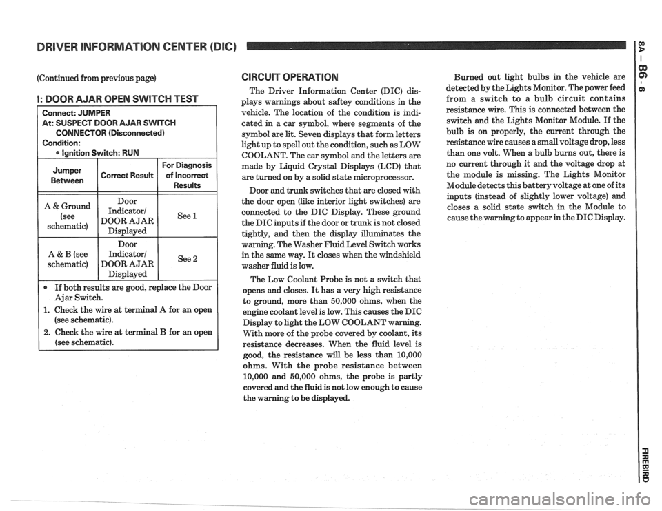
DRIVER INFORMATION CENTER (DIC) I $
(Continued from previous page)
I: DOOR AJAR OPEN SWITCH TEST
At: SUSPECT DOOR AJAR SWITCH
CONNECTOR (Disconnected)
(see schematic).
2. Check the wire at terminal B for an open
(see schematic).
CIRCUIT OPERATION
The Driver Information Center (DIC) dis-
plays warnings about
saftey conditions in the
vehicle. The location of the condition is indi-
cated in a car symbol, where segments of the
symbol are
lit. Seven displays that form letters
light up to spell out the condition, such as LOW
COOLANT. The car symbol and the letters are
made by Liquid
Crystal Displays (LCD) that
are turned on by a solid state microprocessor.
Door and trunk switches that are closed with
the door open (like interior light switches) are
connected to the DIC Display. These ground
the DIC inputs if the door or trunk is not closed
tightly, and then the display illuminates the
warning. The Washer Fluid Level Switch works
in the same way.
It closes when the windshield
washer fluid is low.
The Low Coolant Probe is not a switch that
opens and closes.
It has a very high resistance
to ground, more than 50,000 ohms, when the
engine coolant level is low. This causes the DIC
Display to light the LOW COOLANT w
With more of the probe covered by coolant, its
resistance decreases. When the fluid level is
good, the resistance
will be less than 10,000
ohms. With the probe resistance between
10,000 and 50,000 ohms, the probe is partly
covered and the fluid is not low enough to cause
the warning to be displayed. Burned
out light bulbs in the vehicle are
detected by the Lights Monitor. The power feed
from a switch to a bulb circuit contains
resistance wire. This is connected between the
switch and the Lights Monitor Module.
If the
bulb is on properly, the current through the
resistance wire causes a small voltage drop, less
than one volt. When a bulb burns out, there is
no current through it
and the voltage drop at
the module is missing. The Lights Monitor
Module detects this battery voltage at one of its
inputs (instead of slightly lower voltage) and
closes a solid state switch in the Module to
g to appear in the DIC Display.
Page 1474 of 1825
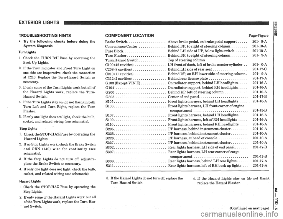
TROUBLESHOOTING HINTS
Try the following checks before doing the
System Diagnosis.
Turn Lights
1. Check the TURN B/U Fuse by operating the
Back Up Lights.
2. If the Turn Indicator and Front Turn Light on
one side are inoperative, check the connection
at
C210. Replace the Turn-Hazard Switch as
necessary.
3. If only some of the Turn Lights work but all of
the Hazard Lights work, replace the
Turn-
Hazard Switch.
4. If the Turn Lights stay on (do not flash) in both
Turn Left and Turn Right, replace the Turn
Flasher.
5. If only one light does not light, check the bulb,
socket, and related wiring (see schematic).
Stop Lights
1. Check the STOP-HAZFuse by operating the
Hazard Lights.
2. If no Stop Lights work, check the Brake Switch
and ORN (140) wire for continuity (see
schematic).
3. If the Stop Lights do not turn off, adjustlre-
place the Brake Switch as necessary.
4. If only one light does not light, check the bulb,
socket, and related wiring (see schematic).
Hazard Lights
1. Check the STOP-HAZ Fuse by operating the
Stop Lights.
2. If only some of the Hazard Lights work but all
of the Turn Lights work, replace the
Turn-Haz-
ard Switch.
COMPONENT LOCATION Page-Figure
................... ..... Brake Switch. Above
brake pedal, on brake pedal support 201- 9-A
.............. ........ Convenience
Center Behind IIP, to right of steering column. 201-10-A
Fuse Block.
..................... Behind LH side of IIP, below light switch. ...... 201-10-A
Turn Flasher
.................... Behind IIP, to right of steering column. ........ 201- 9-A
............. TurnlHazard Switch. Top of steering column
C100 (42 cavities) ................ LH front of dash, left of brake master cylinder .. 201- 0-A
................. ................. C208 (8 cavities) Behind LH side of rear seat. 201-17-C
C210
(11 cavities) ................ Behind IIP, on RN lower side of steering column. 201- 9-A
................. .................... 6312 (2 cavities) Behind rear license plate 201-17-A
............. ..... 6103 (Except VIN E) On radiator support, behind LN headlights 201-16-A
.......................... .... 6104
On radiator support, behind RH headlights. 201-16-A
.......................... ............ 6200 Behind IIP, left of steering column 201-10-A
........................ .......................... 6303 Center of end panel. 201-17-B
.......................... .... S105. Front lights harness, behind LH headlights. 201-16-A
.......................... S106. Front lights harness, LN front corner of engine
compartment..
.......................... 201-1543
.......................... .... S107. Front lights harness, behind LH headlights. 201-16-A
.......................... ..... S109. Front lights harness, left of RH headlights 201-16-A
S110. .......................... Front lights harness, behind RH headlights .... 201-16-A
S205. .......................... IIP harness, behind instrument cluster. ........ 201-10-A
S225. .......................... IIP harness, behind instrument cluster. ........ 201-10-A
S226. .......................... IIP harness, at head of console. ............... 201-10-A
S227. .......................... IIP harness, behind instrument cluster. ........ 201-10-A
S302. .......................... Rear lights harness, LW side of end panel. ...... 201-17-B
.......................... S307. Rear lights harness, LH rear corner of cargo
compartment..
.......................... 201-17-B
.......................... ..... S308. Rear lights harness, behind LH rear lights. 201-17-A
S311. .......................... Rear lights harness, left of RH backup lights ... 201-17-A
3. If the Hazard Lights do not turn off, replace the
4. If the Hazard Lights stay on (do not flash),
Turn-Hazard Switch.
replace the Hazard Flasher.
(Continued on next page)
Page 1476 of 1825
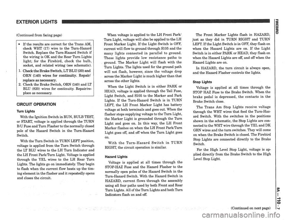
(Continued from facing page)
@ If the results are correct for the Trans AM,
check WHT (17) wire to the Turn-Hazard
Switch. Replace the Turn-Hazard Switch if
the wiring is OK and the Rear Turn Lights
light; for the Firebird, check the bulb,
socket, and related wiring (see schematic).
1. Check the Brake Switch,
LT BLU (20) and
ORN (140) wires for continuity. Repair1
replace as necessary.
2. Check the Brake Switch, ORN (140) and LT
BLU (820) wires for continuity.
Repairlre-
place as necessary.
GlRGUlT OPERATION
Turn Lights
With the Ignition Switch in RUN, BULB TEST,
or START, voltage is applied through the TURN
BIU Fuse and Turn Flasher to the normally closed
pole of the Hazard Switch in the Turn-Hazard
Switch.
With the Turn Switch in TURN LEFT position,
voltage is applied from the Turn Switch through
the LT BLU wires to the LH Turn Indicator and
the LH Front
ParWTurn Light. Voltage is applied
through the YEL wires to the LH Rear Turn
Lights. The lights go on immediately. They begin
to flash when the current flow heats up the tim-
ing element in the flasher and it repeatedly opens
and closes the circuit. When
voltage is applied to the LH Front
Park1
Turn Light, voltage will also be applied to the LH
Front Marker Light. If the Light Switch is OFF,
current will flow to ground through
S105 and the
many lights connected in parallel to ground.
These lights provide low resistance paths to
ground. The Marker Light will flash with the
Turn Lights. The lights used for the ground path
will not flash, however, since the voltage drop
across the Marker Light is much higher than that
across the other lights.
When the Light Switch is in either PARK or
HEAD, voltage is applied through the Tail Fuse,
Light Switch, and
S105 to the Marker and Park
Lights. If the Turn-Hazard Switch is in TURN
LEFT, the LH Front Marker Light has battery
voltage at both terminals and goes out. When the
flasher stops supplying voltage to the Turn Light,
the Marker Light is grounded through the Turn
Light and goes on. In this way, the LN Front
Marker flashes on when the LH Front
ParkITurn
Light goes off, and off when the Turn Light goes The
Front Marker Lights flash in HAZARD,
just as they did in TURN RIGHT and TURN
LEFT. If the Light Switch is in OFF, they flash on
when the Hazard Lights are on. If the Light
Switch is in either PARK or HEAD, they flash on
when the Hazard Lights are off, and off when the
Hazard Lights are on.
In HAZARD, the turn circuit is always open,
and the Hazard Flasher controls the lights.
Stop Lights
Voltage is applied at all times through the
STOP
HA% Fuse to the Brake Switch. When the
brake pedal is depressed, the contacts in the
Brake Switch close.
The Trans Am Stop Lights receive voltage
through the WHT wires that feed the Turn-Haz-
ard Switch. With the switches in the positions
shown in the schematic, the Stop Lights are con-
nected to the WHT wire through the YEL and DK
GRN wires and the turn switches. They will come
on when the Brake Switch is closed. The
Firebird on.
With
RIGHT, Stop
Lights are connected directly to the Brake
the Turn-Hazard Switch in TURN
Switch.
the circuit operation is similar.
For the High Level Stop Light, voltage is ap-
plied directly from the Brake Switch to the Nigh
Hazard Lights Level Stop Light.
Voltage is applied at all times through the
STOP-HAZ Fuse and the Hazard Flasher to the
normally open poles of the Hazard Switch in the
Turn-Hazard Switch. With the Hazard Switch in
HAZARD, current flows through the assembly
using all four paths used by both Front and Rear
Turn Lights. All of the Turn Lights and both Turn
Indicators flash on and off.
(Continued on next page)