ground clearance PONTIAC FIERO 1988 Service User Guide
[x] Cancel search | Manufacturer: PONTIAC, Model Year: 1988, Model line: FIERO, Model: PONTIAC FIERO 1988Pages: 1825, PDF Size: 99.44 MB
Page 399 of 1825
6A3-20 V-8 ENGINE
PLASTIC GAGE
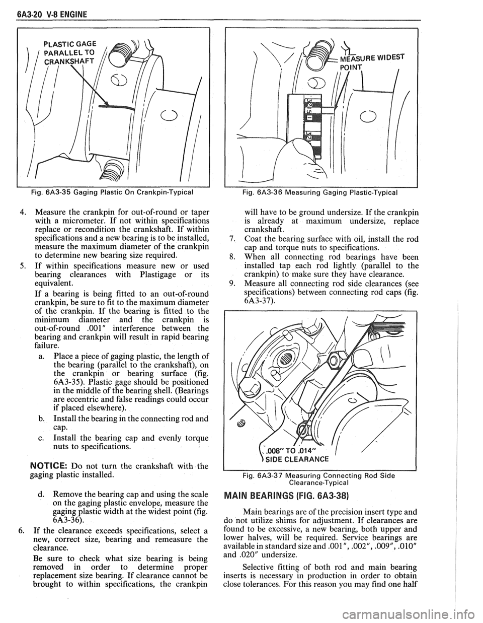
Fig. 6A3-35 Gaging Plastic On Crankpin-Typical
4. Measure the crankpin for out-of-round or taper
with a micrometer. If not within specifications
replace or recondition the crankshaft. If within
specifications and a new bearing is to be installed,
measure the maximum diameter of the
crankpin
to determine new bearing size required.
5. If within specifications measure new or used
bearing clearances with Plastigage or its
equivalent.
If a bearing is being fitted to an out-of-round
crankpin, be sure to fit to the maximum diameter
of the crankpin. If the bearing is fitted to the
minimum diameter and the
crankpin is
out-of-round .OO 1
" interference between the
bearing and
crankpin will result in rapid bearing
failure.
a. Place a piece of gaging plastic, the length of
the bearing (parallel to the crankshaft), on
the
crankpin or bearing surface (fig.
6A3-35). Plastic gage should be positioned
in the middle of the bearing shell. (Bearings
are eccentric and false readings could occur
if placed elsewhere).
b. Install the bearing in the connecting rod and
cap.
c. Install the bearing cap and evenly torque
nuts to specifications.
NOTICE: Do not turn the crankshaft with the
gaging plastic installed.
d. Remove the bearing cap and using the scale
on the gaging plastic envelope, measure the
gaging plastic width at the widest point (fig.
6A3-36).
6. If the clearance exceeds specifications, select a
new, correct size, bearing and remeasure the
clearance.
Be sure to check what size bearing is being
removed in order to determine proper
replacement size bearing. If clearance cannot be
brought to within specifications, the
crankpin
Fig. 6A3-36 Measuring Gaging Plastic-Typical
will have to be ground undersize. If the crankpin
is already at maximum undersize, replace
crankshaft.
7. Coat the bearing surface with oil, install the rod
cap and torque nuts to specifications.
8. When all connecting rod bearings have been
installed tap each rod lightly (parallel to the
crankpin) to make sure they have clearance.
9. Measure all connecting rod side clearances (see
specifications) between connecting rod caps (fig.
6A3-37).
..WS1'TQ.014" 1
s
/
SIDE CLEARANCE
Fig.
6A3-37 Measuring Connecting Rod Side
Clearance-Typical
MAIN BEARINGS (FIG. 8A3-38)
Main bearings are of the precision insert type and
do not utilize shims for adjustment. If clearances are
found to be excessive, a new bearing, both upper and
lower halves, will be required. Service bearings are
available in standard size and
,001 ", .002", .009", .01OV
and .020" undersize.
Selective fitting of both rod and main bearing
inserts is necessary in production in order to obtain
close tolerances. For this reason you may find one half
Page 400 of 1825
V-8 ENGINE 6A3-21
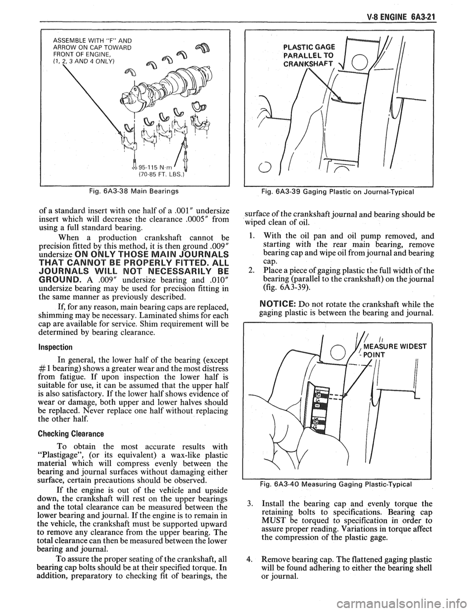
ASSEMBLE WITH 'IF" AND
ARROW ON CAP TOWARD
FRONT OF ENGINE,
(1, 2, 3 AND 4 ONLY)
h a 95-1 15 N.m I t (70-85 FT. LBS.)
Fig. 6A3-38 Main Bearings
of a standard insert with one half of a .00lU undersize
insert which will decrease the clearance
.0005" from
using a full standard bearing.
When a production crankshaft cannot be
precision fitted by this method, it is then ground
.00$"
undersize ON ONLY THOSE MAIN JOURNALS
THAT CANNOT BE PROPERLY FITTED. ALL
JOURNALS
WILL MOT NECESSARILY BE
GROUND.
A .009" undersize bearing and ,010"
undersize bearing may be used for precision fitting in
the same manner as previously described.
If, for any reason, main bearing caps are replaced,
shimming may be necessary. Laminated shims for each
cap are available for service. Shim requirement will be
determined by bearing clearance.
Inspection
In general, the lower half of the bearing (except
# 1 bearing) shows a greater wear and the most distress
from fatigue. If upon inspection the lower half is
suitable for use, it can be assumed that the upper half
is also satisfactory. If the lower half shows evidence of
wear or damage, both upper and lower halves should
be replaced. Never replace one half without replacing
the other half.
Checking Clearance
To obtain the most accurate results with
"Plastigage", (or its equivalent) a wax-like plastic
material which will compress evenly between the
bearing and journal surfaces without damaging either
surface, certain precautions should be observed.
If the engine is out of the vehicle and upside
down, the crankshaft will rest on the upper bearings
and the total clearance can be measured between the
lower bearing and journal. If the engine is to remain in
the vehicle, the crankshaft must be supported upward
to remove any clearance from the upper bearing. The
total clearance can then be measured between the lower
bearing and journal.
To assure the proper seating of the crankshaft, all
bearing cap bolts should be at their specified torque. In
addition, preparatory to checking fit of bearings, the
Fig. 6A3-39 Gaging Plastic on Journal-Typical
surface of the crankshaft journal and bearing should be
wiped clean of oil.
1. With the oil pan and oil pump removed, and
starting with the rear main bearing, remove
bearing cap and wipe oil from journal and bearing
cap.
2. Place a piece of gaging plastic the full width of the
bearing (parallel to the crankshaft) on the journal
(fig. 6A3-39).
NOTICE: Do not rotate the crankshaft while the
gaging plastic is between the bearing and journal.
Fig. 6A3-40 Measuring Gaging Plastic-Typical
3. Install the bearing cap and evenly torque the
retaining bolts to specifications. Bearing cap
MUST be torqued to specification in order to
assure proper reading. Variations in torque affect
the compression of the plastic gage.
4. Remove bearing cap. The flattened gaging plastic
will be found adhering to either the bearing shell
or journal.
Page 452 of 1825
CRANKING SYSTEM CD2-1
CRANK NG SYSTEM
General Description ................................. 6D2-1 Service Procedures .................................. 6D2-3
Cranking System ......................... ... ........ 6D2- 1 Cranking
System ..................... .. ............. 6D2-3
Starter Motor ............................................. 6D2-1 On-Car Service ....................................... 6D2-4 Solenoid .................................................. 6D2- 1
Starter ........................... ... ...................... 6D2-4 Diagnosis ..................................................... 6D2-1 Specifications ............................................. 6D2- I I Cranking System ......................... ... ...... 6D2- 1
Unit Repair ............................................ 6D2-6- 1 1
GENERAL DESCRIPTION
The engine electrical system includes the battery, Battery: To determine the condition of the
ignition (primary and secondary), starter (and related battery,
follow the testing procedure outlined in the
wiring) and the generator (and related wiring). Battery section
(6D1).
Diagnostic charts (see Section 6D) will aid in Wiring: Inspect the wiring for damage. Inspect trouble-shooting system faults. When a fault is traced all connections to the cranking motor, solenoid, to a articular component, refer to that components' ignition switch and battery, including all ground
section of the service manual.
connections. Clean and tighten all connections, as
CRANKING SYSTEM
The cranking circuit consists of the battery,
starting motor, ignition switch, and related electrical
wiring. These components are connected electrically as
shown in Fig. 1.
Starter Motor
Wound field starter motors have pole pieces,
arranged around the armature, that are energized by
wound field coils.
Solenoid
Enclosed shift lever cranking motors have the
shift lever mechanism and the solenoid plunger
enclosed in the drive housing, protecting them from
exposure to dirt, icing conditions and splash.
In the basic circuit shown in Fig. 1, solenoid
windings are energized when the switch is closed. The
resulting plunger and shift lever movement causes the
pinion to engage the engine flywheel ring gear and the
solenoid main contacts to close, and cranking takes
place. When the engine starts, pinion overrun protects
the armature from excessive speed until the switch is
opened, at which time the return spring causes the
pinion to disengage. To prevent excessive overrun, the
switch should open immediately when the engine
starts.
DIAGNOSIS
CRANKING SYSTEM
Before removing any unit in a cranking circuit for
repair, the following checks should be made:
Electrical System General Diagnosis:
Follow the procedures shown in Section 6D to isolate
problem. required.
Solenoid
and Ignition Switch: Inspect all
switches to determine their condition.
Starter Motor Noise: To correct starter motor
noise during starting, use the following procedure:
1. Refer to Fig. 2 to determine the problem.
2. If the complaint is noise, correction can be
achieved by proper "shimming" as follows:
a. Check
flywheel for damage
- bent flywheel,
unusual wear, etc.
b. Start
engine and carefully touch outside
diameter of rotating flywheel ring gear with
chalk or crayon to show high point of tooth
runout. Turn engine off and rotate flywheel
so that the marked teeth are in the area of
the starter pinion gear.
c. Disconnect negative battery cable to
prevent cranking of engine.
d. Check pinion to flywheel clearance, as
shown in Fig. 3, by using a wire gage of
.5mm (.02OU) minimum thickness (or
diameter). Center a pinion tooth between
two flywheel teeth and gage, as shown in
Fig. 3. Do not gage in the corners, where a
misleading larger dimension may be
observed. If the clearance is under this
minimum, shimming the starter away from
the flywheel is required.
e. If
the clearance is grossly over
.5mm (.02OU)
in the vicinity of 1.5mm (.06OU) or more,
shimming the starter toward the flywheel is
required. (This is generally the problem
causing broken flywheel teeth or starter
housings.) Shimming the starter toward the
flywheel can be accomplished by shimming
only the outboard starter mounting pad.
A
shim of .4mm (.015") thickness, at this