jump cable PONTIAC FIERO 1988 Service User Guide
[x] Cancel search | Manufacturer: PONTIAC, Model Year: 1988, Model line: FIERO, Model: PONTIAC FIERO 1988Pages: 1825, PDF Size: 99.44 MB
Page 1186 of 1825
TROUBLESHOOTING TESTS m r rn 0
With a Short Finder
1. Remove the blown fuse, leaving the Battery
connected.
2. Connect the Short Finder across the fuse
terminals.
3. Close all switches in series with the circuit
you are troubleshooting.
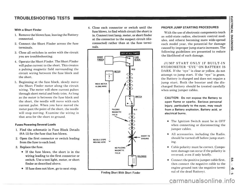
4. Operate the Short Finder. The Short Finder
will pulse current to the short. This creates
a pulsing magnetic field surrounding the
circuit wiring between the fuse block and
the short.
5. Beginning at the fuse block. slowly move
the Short Finder meter along the circuit
wiring. The meter will show current pulses
through sheet
inetal and body trim. As long
as the meter is between the fuse block and
the short, the needle will move with each
current pulse. When you have
moved the
meter past the point of the short. the needle
will stop
moving. Examine the wiring in
that area for the short to ground.
Fuses Powering Several Loads
1. Find the schematic in Fuse Block Details
(8A-11) for the fuse that has blown.
2. Open the first connector or switch leading
from the fuse to each load.
3. Replace the fuse.
@ If the fuse blows, the short is in the
wiring leading to the first connector or
switch. Use a test light, meter, or short
finder as described above.
@ If fuse does not blow, go to next step.
4. Close each connector or switch until the PROPER JUMP STARTING PROCEDURES
fuse blows, to find which circuit the short is
With the use of electronic components (such
in. Connect test lamp, meter, or short finder
as solid-state radios, electronic control
mod- at the connector to the suspect circuit (dis- ules, and others) becoming more wide-spread
connected) rather than at the fuse termi- each model year, the potential for damage nals. caused by improper jump starts increases. The
SHORT FUSE FINDER - BLOCK -
MOVE METER
NEEDLE STOPS
MOVING HERE
NO PULSING
MAGNETIC
FIELD
Cb
SHORT TO
GROUND
w-
Finding Short With Short Finder
following guidelines are presented to reduce
the likelihood of such damage.
JUMP START ONLY IF BUILT-IN
HYDROMETER "EYE" ON BATTERY IS
DARK. If the "eye" is clear or yellow, do not
attempt to jump start. If the "eye" is green,
the Battery is charged and does not require a
jump start. Both the booster and the dis-
charged Battery should be treated carefully
when using jumper cables.
CAUTION: Do not expose the Battery to
open flame or sparks. Serious personal
injury, particularly
to the eyes, may result
from
a Battery explosion, Battery acid, or
electrical burns.
The Ignition Switch must be in OFF
when connecting or disconnecting the
jumper cables.
All accessories. including the Radio.
should be turned off before jump start-
ing.
Cable polarity must be correct. Compo-
nent damage can occur
if the polarity is
re~~ersed. even if only briefly.
a Connect the positive jumper cable first.
then connect the negative cable to the
engine ground (not the negative termi-
nal of the dead Battery).
Page 1426 of 1825
INSTRUMENT PANEL: DIGITAL CLUSTER
6: TAGHOMETER DOES NOT
OPEWTE
Disconnect the Ignition coil connector and con-
nect the matingcable from tester 5-33431 to the
connector. Plug in the tester and set the
switches to ON and 54 mph. Switch the Igni-
tion to RUN and observe the Tachometer.
If the Tachometer reads 900 rpm
(V8), or
1350
rpm (V6), check the EST Distributor or
Ignition Coil for an open.
If the Tachometer does not read correctly,
check the WHT (121) wire for an open. If OK,
replace the Instrument Cluster (See Section
8C).
D: TEMPEFIATURE DISPWY ALWAYS
SHOW nm
Disconnect the Coolant Temperature Sender.
Tum the Ignition Switch to RUN and observe
the Temperature Gage.
If the Display now reads cold, replace the
Coolant Temperature Sender.
* If the display still reads hot, check the DK
GRNIWHT (35) wire for a short to ground
(see schematic). If
OK, replace the Instru-
ment Cluster (See Section
86).
E: TEMPEFIATURE DISPLPIY ALMS
SHOWS GOLD
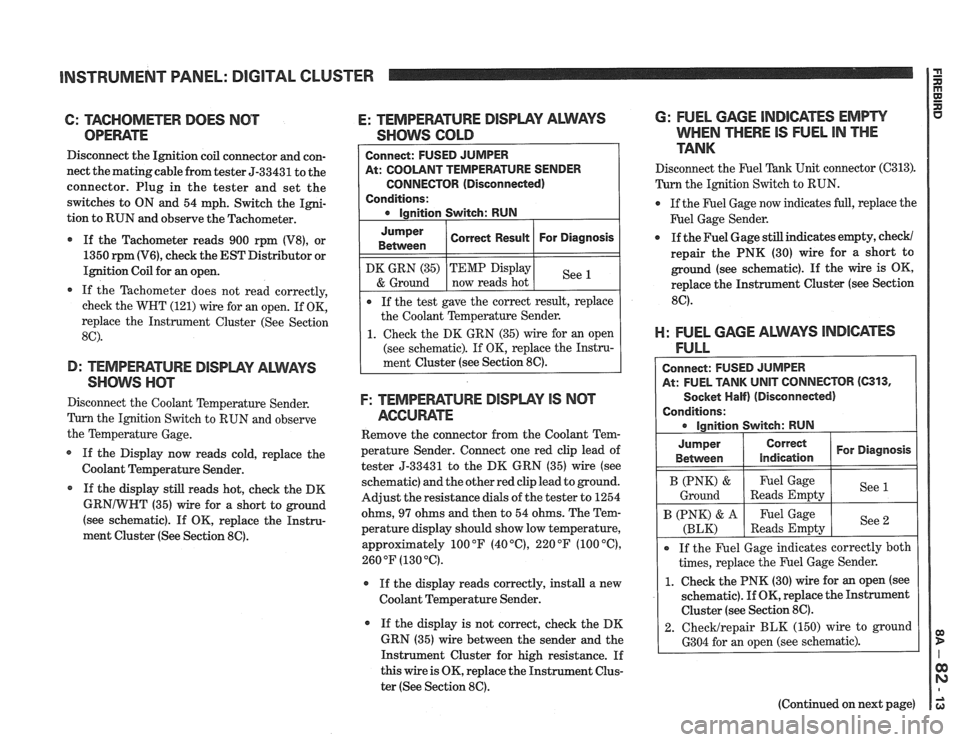
At: COOLANT TEMPERATURE SENDER
CONNECTOR (Disconnected)
Conditions:
Jumper
Between
F: TEMPEWTURE DISPWY IS NCIT
AGCUME
Remove the connector from the Coolant Tem-
perature Sender. Connect one red clip lead of
tester 5-33431 to the DK GRN (35) wire (see
schematic) and the other red clip lead to ground.
Adjust the resistance dials of the tester to 1254
ohms,
97 ohms and then to 54 ohms. The Tem-
perature display should show low temperature,
approximately 100
OF (40 "C), 220 OF (100 "C),
260 OF (130 "6).
r If the display reads correctly, install a new
Coolant Temperature Sender.
If the display is not correct, check the DK
GRN (35) wire between the sender and the
Instrument Cluster for high resistance. If
this wire is OK, replace the Instrument Clus-
ter (See Section
8C).
DK GRN (35)
& Ground
6: FUEL GAGE INDICATES EMPW
WHEN THERE IS FUEL IN THE
TANK
Correct Result
Disconnect the F'uel Tank Unit connector (C313).
Turn the Ignition Switch to RUN.
For Diagnosis
If the test gave the correct result, replace
the Coolant Temperature Sender.
1. Check the DK GRN (35) wire for an open
(see schematic). If OK, replace the Instru-
ment Cluster (see Section
8C).
TEMP Display
now reads hot
@ If the Fuel Gage now indicates full, replace the
F'uel Gage Sender.
See
a If the Fuel Gage still indicates empty, check/
repair the PNK (30) wire for a short to
ground (see schematic). If the wire is OK,
replace the Instrument Cluster (see Section
8C).
El: FUEL GAGE ALWAYS lNDl6ATES
FULL
Connect: FUSED JUMPER
At: FUEL TANK
UNIT CONNECTOR (C313,
Socket Half) (Disconnected)
Conditions: ignition Switch: RUN
I B (PNK) & I Fuel Gage I See (
Ground Reads Empty
Jumper
Between
If the Fuel Gage indicates correctly both
times, replace the Fuel Gage Sender.
1. Check the PNK (30) wire for an open (see
schematic).
If OK, replace the Instrument
Cluster (see Section
8C).
2. ChecMrepair BLK (150) wire to ground
6304 for an open (see schematic).
Correct
indication
B (PNK) & A
(BLK)
(Continued on next page)
For Diagnosis
Fuel Gage
Reads Empty See
2
Page 1559 of 1825
POWER ANTENNA
(Continued from previous page) the relay contacts. The motor drives the
Antenna up. At the end of its travel, the Up
Switch opens and the motor stops.
A: ANTENNA DOES NOT OPERATE When the Radio or ignition is turned off,
(TABLE 2) the circuit through the Antenna Relay coil
opens. The contacts open to the position
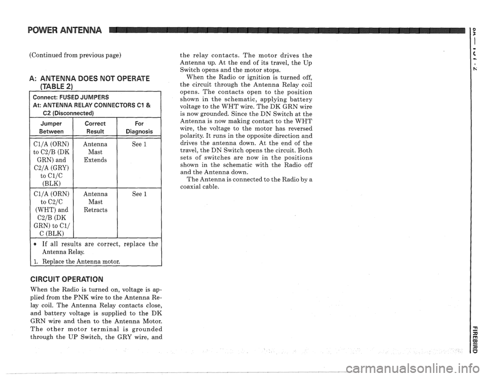
Connect: FUSED JUMPERS shown in the schematic, applying battery At: ANTENNA RELAY CONNECTORS C1 & voltage to the WHT wire. The DK GRN wire
1 62 (Disconnected) I
Cl/A (ORN)
to
C2/B (DK
GRN) and
C2/A (GRY)
to ci/c
(BLK)
Antenna
Mast
Extends See 1
If all results are correct,
replace the
Antenna Relay.
I 1. Redace the Antenna motor. is
now grounded.
Since the DN Switch at the
Antenna is now making contact to the WNT
wire, the voltage to the motor has reversed
polarity. It runs in the opposite direction and
drives the antenna down. At the end of the
travel, the DN Switch opens the circuit. Both
sets of switches are now in the positions
shown in the schematic with the Radio off
and the Antenna down.
The Antenna
is connected to the Radio by a
coaxial cable.
CIRCUIT OPERATION
When the Radio is turned on, voltage is ap-
plied from the PNK wire to the Antenna Re-
lay coil. The Antenna Relay contacts close,
and battery voltage is supplied to the
DK
GRN wire and then to the Antenna Motor.
The other motor terminal is grounded
through the UP Switch, the GRY wire, and