AUX PONTIAC FIERO 1988 Service Repair Manual
[x] Cancel search | Manufacturer: PONTIAC, Model Year: 1988, Model line: FIERO, Model: PONTIAC FIERO 1988Pages: 1825, PDF Size: 99.44 MB
Page 51 of 1825
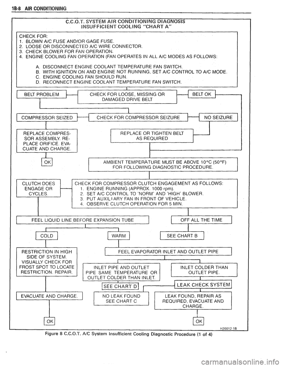
1B-8 AIR CONDITIONING
INSUFFICIENT COQblNG "CHART A
A/C FUSE AND/OR GAGE FUSE.
OR DISCONNECTED
AlC WIRE CONNECTOR.
. CHECK BLOWER FOR FAN OPERATION.
. ENGINE COOLING FAN OPERATION (FAN OPERATES IN ALL A/C MODES AS FOLLOWS:
A. DISCONNECT ENGINE COOLANT TEMPERATURE FAN SWITCH.
8. WITH IGNITION ON AND ENGINE NOT RUNNING, SET A/C CONTROL TO A/C MODE.
C. ENGINE COOLING FAN SHOULD RUN.
D. RECONNECT ENGINE COOLANT TEMPERATURE FAN SWITCH.
REPLACE COMPRES-
SOR ASSEMBLY. RE-
PLACE ORIFICE. EVA-
CUATE AND CHARGE. AS
REQUIRED
AND 'HIGH' BLOWER.
T
AUXIL I ARY FAN IN T OF VEHICLE.
I OFF ALL THE TIME I
RESTRICTION IN HIGH
SIDE OF SYSTEM.
VISUALLY CHECK FOR
FROST SPOT TO LOCATE
RESTRICTION. REPAIR.
Figure
8 C.C.O.T. NC System Insufficient Cooling Diagnostic Procedure (1 of 4)
Page 367 of 1825
6A2-16 2.8 LITER V-6
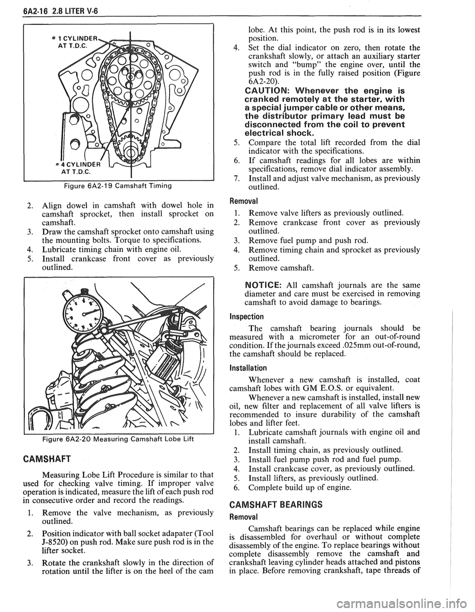
Figure 6A2-19 Camshaft Timing
2. Align dowel in camshaft with dowel hole in
camshaft sprocket, then install sprocket on
camshaft.
3. Draw the camshaft sprocket onto camshaft using
the mounting bolts. Torque to specifications.
4. Lubricate timing chain with engine oil.
5. Install crankcase front cover as previously
outlined.
Figure 6A2-20 Measuring Camshaft Lobe Lift
CAMSHAFT
Measuring Lobe Lift Procedure is similar to that
used for checking valve timing. If improper valve
operation is indicated, measure the lift of each push rod
in consecutive order and record the readings.
1. Remove the valve mechanism, as previously
outlined.
2. Position
indicator with ball socket adapater (Tool
5-8520) on push rod. Make sure push rod is in the
lifter socket.
3. Rotate the crankshaft slowly in the direction of
rotation until the lifter is on the heel of the cam lobe.
At this point, the push rod is in its lowest
position.
4. Set the dial indicator on zero, then rotate the
crankshaft slowly, or attach an auxiliary starter
switch and "bump" the engine over, until the
push rod is in the fully raised position (Figure
6A2-20).
CAUTION: Whenever the engine is
cranked remotely at the starter, with
a special jumper cable or other means,
the distributor primary lead must be
disconnected from the coil to prevent
electrical shock.
5. Compare the total lift recorded from the dial
indicator with the specifications.
6. If camshaft readings for all lobes are within
specifications, remove dial indicator assembly.
7. Install and adjust valve mechanism, as previously
outlined.
Removal
1. Remove valve lifters as previously outlined.
2. Remove crankcase front cover as previously
outlined.
3. Remove fuel pump and push rod.
4. Remove timing chain and sprocket as previously
outlined.
5. Remove camshaft.
NOTICE: All camshaft journals are the same
diameter and care must be exercised in removing
camshaft to avoid damage to bearings.
Inspection
The camshaft bearing journals should be
measured with a micrometer for an out-of-round
condition. If the journals exceed
.025mm out-of-round,
the camshaft should be replaced.
Installation
Whenever a new camshaft is installed, coat
camshaft lobes with
GM E.O.S, or equivalent.
Whenever a new camshaft is installed, install new
oil, new filter and replacement of all valve lifters is
recommended to insure durability of the camshaft
lobes and lifter feet.
1. Lubricate camshaft journals with engine oil and
install camshaft.
2. Install timing chain, as previously outlined.
3. Install fuel pump push rod and fuel pump.
4. Install crankcase cover, as previously outlined.
5. Install
lifters, as previously outlined.
6. Complete build up of engine.
CAMSHAFT BEARINGS
Removal
Camshaft bearings can be replaced while engine
is disassembled for overhaul or without complete
disassembly of the engine. To replace bearings without
complete disassembly remove the camshaft and
crankshaft leaving cylinder heads attached and pistons
in place. Before removing crankshaft, tape threads of
Page 396 of 1825
V-8 ENGINE 6A3.17
4. Set dial indicator on zero, then rotate the
crankshaft slowly, or attach an auxiliary starter
switch and "bump" the engine over, until the
push rod is fully raised position.
e Whenever the engine is cranked remotely at
the started, with a special jumper cable or
other means, the distributor primary lead
should be disconnected from the distributor
(coil).
5. Compare the total lift recorded from the dial
indicator with specifications.
6. If camshaft readings for all lobes are within
specifications, remove dial indicator assembly.
7. Install and adjust valve mechanism as outlined.
Removal
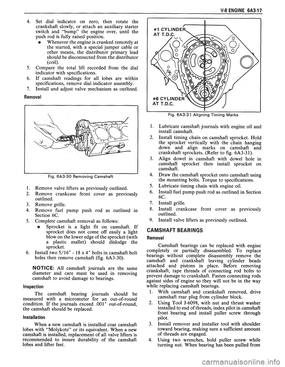
Fig. 6A3-30 Removing Camshaft
1.
Remove valve lifters as previously outlined.
2. Remove crankcase front cover as previously
outlined.
3. Remove grille.
4. Remove fuel pump push rod as outlined in
Section 6C.
5. Complete camshaft removal as follows:
e Sprocket is a light fit on camshaft. If
sprocket does not come off easily a light
blow on the lower edge of the sprocket (with
a plastic mallet) should dislodge the
sprocket.
6. Install two 5/16" - 18 x 4" bolts in camshaft bolt
holes then remove camshaft (fig. 6A3-30).
NOTICE: All camshaft journals are the same
diameter and care must be used in removing
camshaft to avoid damage to bearings.
Inspection
The camshaft bearing journals should be
measured with a micrometer for an out-of-round
condition. If the journals exceed
.001" out-of-round,
the camshaft should be replaced.
Installation
When a new camshaft is installed coat camshaft
lobes with "Molykote" or its equivalent. When a new
camshaft is installed, replacement of all valve lifters is
recommended to insure durability of the camshaft
lobes and lifter feet.
Fig. 6A3-3 1 Aligning Timing Marks
Lubricate camshaft journals with engine oil and
install camshaft.
Install timing chain on camshaft sprocket. Hold
the sprocket vertically with the chain hanging
down and align marks on camshaft and
crankshaft sprockets. (Refer to fig. 6A3-3 1).
Align dowel in camshaft with dowel hole in
camshaft sprocket then install sprocket on
camshaft.
Draw the camshaft sprocket onto camshaft using
the mounting bolts. Torque to specifications.
Lubricate timing chain with engine oil.
Install fuel pump push rod as outlined in Section
6C.
Install grille.
Install crankcase front cover as previously
outlined.
Install valve lifters as previously outlined.
CAMSHAFT BEARINGS
Removal
Camshaft bearings can be replaced with engine
completely or partially disassembled. To replace
bearings without complete disassembly remove the
camshaft and crankshaft leaving cylinder heads
attached and pistons in place. Before removing
crankshaft, tape threads of connecting rod bolts to
prevent damage to crankshaft. Fasten connecting rods
against sides of engine so they will not be in the way
while replacing camshaft bearings.
1. With camshaft and crankshaft removed, drive
camshaft rear plug from cylinder block.
2. Using Tool J-6098, with nut and thrust washer
installed to end of threads, index pilot in camshaft
front bearing and install puller screw through
pilot.
3. Install remover and installer tool with shoulder
toward bearing, making sure a sufficient amount
of threads are engaged.
4. Using two wrenches, hold puller screw while
turning nut. When bearing has been pulled from
Page 417 of 1825
6B-8 ENGINE COOLING
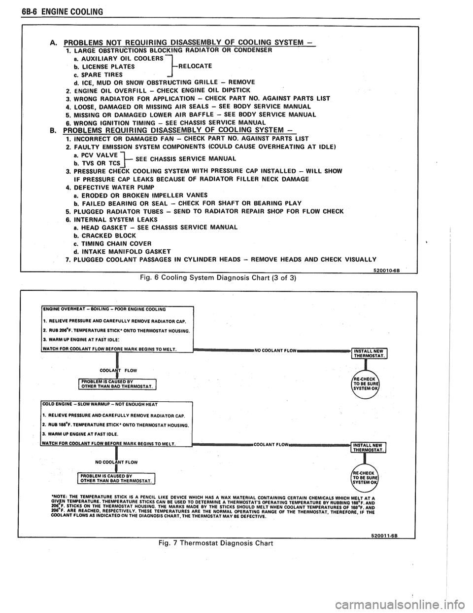
PROBLEMS NOT REQUIRING DISASSEMBLY OF COOLING SYSTEM - 1. LARGE OBSTRUCTIONS BLOCKING RADIATOR OR CONDENSER
a. AUXILIARY OIL COOLERS
b. LICENSE PLATES R ELOCATE
c. SPARE TIRES
d. ICE, MUD OR SNOW OBSTRUCTING GRILLE - REMOVE
2. ENGINE OIL OVERFILL - CHECK ENGINE OIL DIPSTICK
3. WRONG RADIATOR FOR
APPLICATION - CHECK PART NO. AGAINST PARTS LlST
4. LOOSE, DAMAGED OR MISSING AIR SEALS - SEE BODY SERVICE MANUAL
5. MISSING OR DAMAGED LOWER AIR BAFFLE - SEE BODY SERVICE MANUAL
6. WRONG IGNITION TIMING - SEE CHASSIS SERVICE MANUAL PROBLEMS REQUIRING DISASSEMBLY OF COOLING SYSTEM -
1. INCORRECT OR DAMAGED FAN - CHECK PART NO. AGAINST PARTS LlST
2. FAULTY EMISSION SYSTEM COMPONENTS (COULD CAUSE OVERHEATING AT IDLE)
; SEE CHASSIS SERVICE MANUAL
3. PRESSURE CHECK COOLING SYSTEM WITH PRESSURE CAP INSTALLED - WILL SHOW
IF PRESSURE CAP LEAKS BECAUSE OF RADIATOR FILLER NECK DAMAGE
4. DEFECTIVE WATER PUMP
a. ERODED OR BROKEN IMPELLER VANES
b. FAILED BEARING OR SEAL - CHECK FOR SHAFT OR BEARING PLAY
5. PLUGGED RADIATOR TUBES - SEND TO RADIATOR REPAIR SHOP FOR FLOW CHECK
6. INTERNAL SYSTEM LEAKS
B. HEAD GASKET - SEE CHASSIS SERVICE MANUAL
b. CRACKED BLOCK
c. TIMING CHAIN COVER
d. INTAKE MANIFOLD GASKET
7. PLUGGED COOLANT PASSAGES IN CYLINDER HEADS - REMOVE HEADS AND CHECK VISUALLY
Fig. 6 Cooling System Diagnosis Chart (3 of 3)
1. RELIEVE PRESSURE AND CAREFULLY REMOVE RADIATOR CAP.
2. RUB W'F. TEMPERATURE STICK* ONTO THERMOSTAT MOUSING.
3. WARM UP ENGINE AT FAST IDLE:
WATCH FOR COOLANT FLOW BEFORE MAR
NO COOLANT FLOW INSTALL NEW
THERMOSTAT.
COLD ENGINE -SLOW WARMUP -NOT ENOUGH HEAT
1. RELIEVE PRESSURE AND CAREFULLY REMOVE RADIATOR CAP.
2. RUB 188'~. TEMPERATURE STICK' ONTO THERMOSTAT HOUSING.
3. WARM UP ENGINE AT FAST IDLE.
COOLANT FLOW
- 'NOTE: THE TEMPERATURE STICK IS A PENCIL LIKE DEVICE WHICH HAS A WAX MATERIAL CONTAINING CERTAIN CHEMICALS WHICH MELT AT A GIVEN TEMPERATURE THEWERATURE STICKS CAN BE USED TO DETERMINE A THERMOSTAT'S OPERATING TEMPERATURE BY RUBBING laB°F AN0 =OF. STICKS ON THE THERMOSTAT HOUSING. THE MARKS MADE BY THE STICKS SHOULD MELT WHEN COOLANT TEMPERATURES OF IWOF'AND W'F. ARE REACHED, RESPECTIVELY. THESE TEMPERATURES ARE THE NORMAL WERATING RANGE OF THE THERMOSTAT. THEREFORE, ~i WE COOLANT FLOWS AS INDICATED ON THE DIAGNOSIS CHART. THE THERMOSTAT MAY BE DEFECTIVE.
Fig. 7 Thermostat Diagnosis Chart
Page 447 of 1825
6D1-4 BATTERY
VOLTAGE
A. 16.0 or more
B. 14.0
- 15.9
C. 13.9 or less HOURS
1. Set parking brake and place automatic
Up to 4 Hours transmission in "PARK" (NEUTRAL for
Up to 8 Hours manual transmission.) Turn off the ignition,
Up to 16 Hours turn off lights, and all other electrical
If the charge current is still not
measurable
at the end of the above charging
times, the battery should be replaced.
If the charge current is measurable during
the charging time, the battery is considered to be
good and charging should be completed in the
normal manner.
5. It
is important to remember that a completely
discharged battery must be recharged for a
sufficient number of ampere hours (AH) to
restore it to a usable state. As a general rule of
thumb, using the reserve capacity rating (RC) of
the battery as the number of ampere hours of
charge will usually bring the green dot into view.
For example, if battery is rated at 75 RC minutes,
it would be completely recharged as follows:
10 ampere charge x 7-1/2 hours
= 75 AH
25 ampere charge x 3 hours = 75 AH, etc.
6. It
is recommended that any battery recharged by
this procedure be
LOAD TESTED to establish
serviceability.
JUMP STARTING IN CASE OF EMERGENCY
WITH AUXILIARY (BOOSTER) BAVEEWY
NOTICE: Do not push or tow the vehicle to start.
Damage to the emission system, or to other parts
of the vehicle may result.
Both booster and discharged battery should be
treated carefully when using jumper cables. Follow the
procedure outlined below, being careful not to cause
sparks:
CAUTION: Departure from these
conditions or the procedure below
could result in:
(1) Serious personal
injury (particularly to eyes) or property
damage from such causes as battery
explosion, battery acid, or electrical
burns; and/or
(2) damage to electronic
components of either vehicle.
Never expose battery to open flame or electric
spark
- batteries generate a gas which is flammable and
explosive.
Remove rings, watches, and other jewelry. Wear
approved eye protection.
Do not allow battery fluid to contact eyes, skin,
fabrics, or painted surfaces
- fluid is a corrosive acid.
Flush any contacted area with water immediately and
thoroughly. Be careful that metal tools or jumper
cables do not contact the positive battery terminal (or
metal in contact with it) and any other metal on the
car, because a short circuit could occur. Batteries
should always be kept out of the reach of children.
loads.
2. Check the built-in hydrometer. If it is clear or
light yellow, replace the battery.
3. Attach the end of one jumper cable to the positive
terminal of the booster battery and the other end
of the same cable to the positive terminal of the
discharged battery. Do not permit vehicles to
touch each other as this could cause a ground
connection and counteract the benefits of this
procedure. (Use 12-volt battery only to jump start
the engine).
4. Attach one end of the remaining negative cable
to the negative terminal of the booster battery,
and the other end to a solid engine ground (such
as
A/C compresser bracket or generator
mounting bracket) at least 18 inches from the
battery of the vehicle being started (DO NOT
CONNECT DIRECTLY TO THE NEGATIVE
TERMINAL OF THE DEAD BATTERY).
5. Start the engine of the vehicle that is providing
the jump start and turn off electrical accessories.
Then start the engine in the car with the
discharged battery.
6. Reverse these directions exactly when removing
the jumper cables. The negative cable must be
disconnected from the engine that was jump
started first.
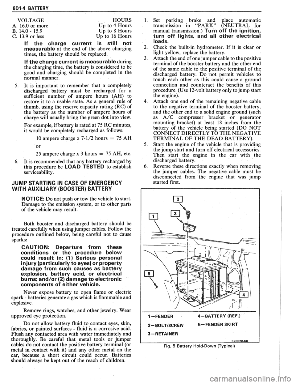
I-FENDER 4-BATTERY (REF.)
2- BOLTISCREW 5-FENDER SKIRT
3-RETAINER
520028-60
Fig. 5 Battery Hold-Down (Typical)
Page 1001 of 1825
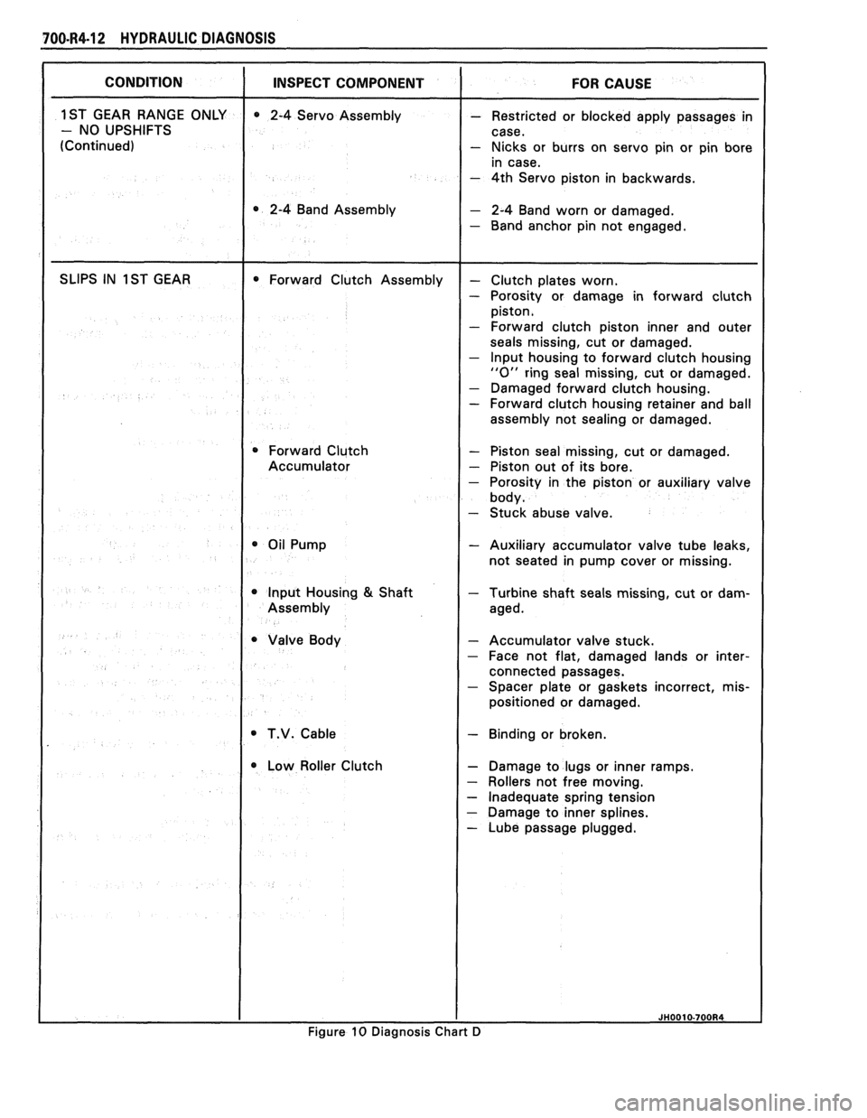
700-R4-12 HY DRAULlC DIAGNOSIS
- Nicks or burrs on servo pin or pin bore
- 4th Servo piston in backwards.
0 2-4 Band Assembly - 2-4 Band worn or damaged.
- Band anchor pin not engaged.
seals missing, cut or damaged.
- lnput housing to forward clutch housing
"0" ring seal missing, cut or damaged.
- Damaged forward clutch housing. - Forward clutch housing retainer and ball
assembly not sealing or damaged.
0 Forward Clutch - Piston seal missing, cut or damaged.
Accumulator
- Piston out of its bore.
- Stuck abuse valve.
- Auxiliary accumulator valve tube leaks,
not seated in pump cover or missing.
Input Housing
& Shaft - Turbine shaft seals missing, cut or dam-
- Accumulator valve stuck. - Face not flat, damaged lands or inter-
connected passages.
- Spacer plate or gaskets incorrect, mis-
positioned or damaged.
T.V. Cable - Binding or broken.
Low Roller Clutch
- Damage to lugs or inner ramps.
- Rollers not free moving.
- Inadequate spring tension
- Damage to inner splines.
- Lube passage plugged.
Figure
10 Diagnosis Chart D
Page 1005 of 1825
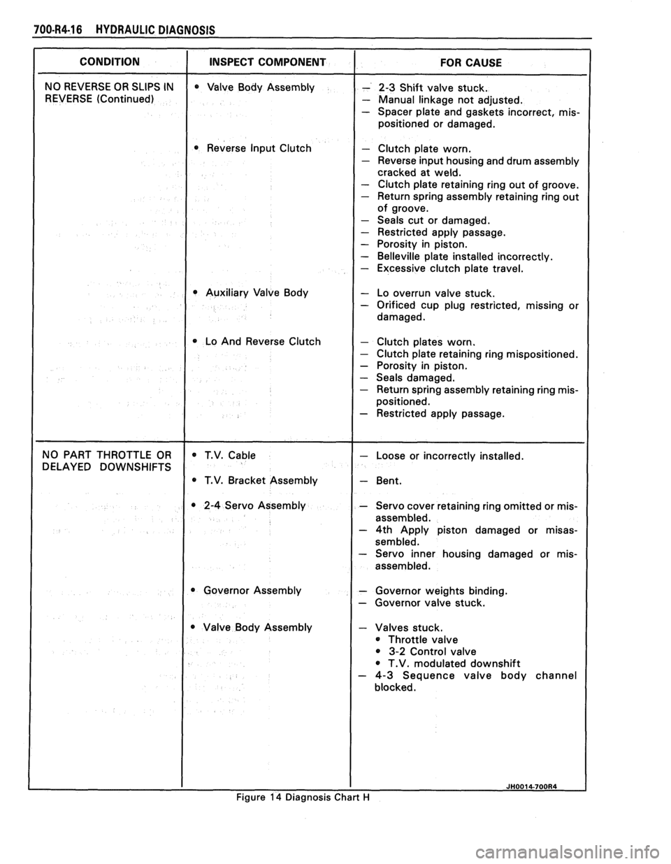
700-R4-16 HYDRAULIC DIAGNOSIS
I CONDITION I INSPECT COMPONENT I FOR CAUSE
NO REVERSE OR SLIPS IN
REVERSE (Continued) Valve
Body Assembly
Reverse Input Clutch
Auxiliary Valve Body
1 Lo And Reverse Clutch
- 2-3 Shift valve stuck.
- Manual linkage not adjusted.
- Spacer plate and gaskets incorrect, mis-
positioned or damaged.
Clutch plate worn.
Reverse input housing and drum assembly
cracked at weld.
Clutch plate retaining ring out of groove.
Return spring assembly retaining ring out
of groove.
Seals cut or damaged.
Restricted apply passage.
Porosity in piston.
Belleville plate installed incorrectly.
Excessive clutch plate travel.
- Lo overrun valve stuck. - Orificed cup plug restricted, missing or
damaged.
- Clutch plates worn. - Clutch plate retaining ring mispositioned.
- Porosity in piston.
- Seals damaged. - Return spring assembly retaining ring mis-
positioned.
- Restricted apply passage.
NO PART THROTTLE OR
DELAYED DOWNSHIFTS T.V.
Cable
T.V. Bracket Assembly
2-4 Servo Assembly
Governor Assembly
Valve Body Assembly
I
- Loose or incorrectly installed.
- Bent.
- Servo cover retaining ring omitted or mis-
assembled.
- 4th Apply piston damaged or misas-
sembled. - Servo inner housing damaged or mis-
assembled.
- Governor weights binding.
- Governor valve stuck.
- Valves stuck.
Throttle valve
3-2 Control valve
T.V. modulated downshift
- 4-3 Sequence valve body channel
blocked.
I I JH0014-700R4
Figure 14 Diagnosis Chart H
Page 1054 of 1825
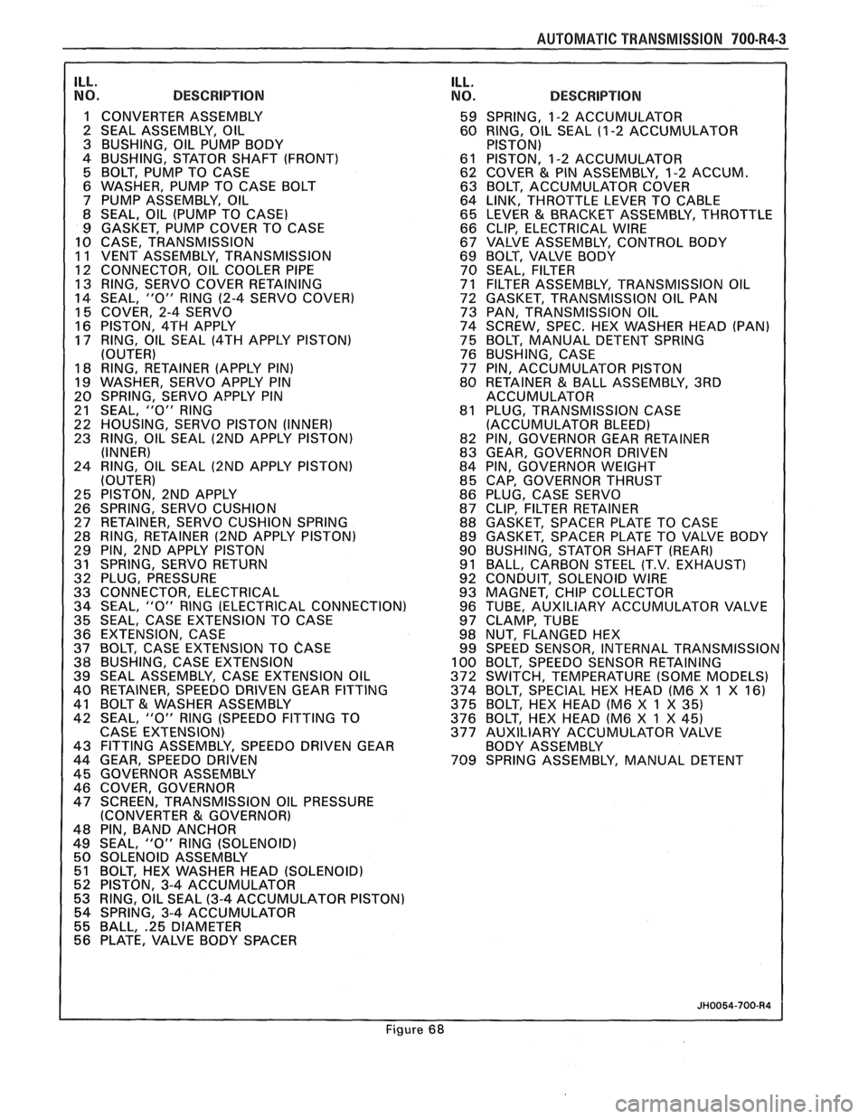
AUTOMAT lC TRANSMISSION 700-R4-3
ILL. NO. DESCRIPTION
1 CONVERTER ASSEMBLY
2 SEAL ASSEMBLY, OIL
3 BUSHING, OIL PUMP BODY
4 BUSHING, STATOR SHAFT (FRONT)
5 BOLT, PUMP TO CASE
6 WASHER, PUMP TO CASE BOLT
7 PUMP ASSEMBLY, OIL
8 SEAL, OIL (PUMP TO CASE)
9 GASKET, PUMP COVER TO CASE
10 CASE, TRANSMISSION
11 VENT ASSEMBLY, TRANSMISSION
1 12 CONNECTOR, OIL COOLER PIPE 13 RING, SERVO COVER RETAINING
14 SEAL, "0" RlNG
(2-4 SERVO COVER)
15 COVER, 2-4 SERVO
16 PISTON, 4TH APPLY
17 RING, OIL SEAL
(4TH APPLY PISTON)
(OUTER)
18 RING, RETAINER (APPLY PIN)
19 WASHER, SERVO APPLY PIN
20 SPRING, SERVO APPLY PIN
21 SEAL,
"0" RlNG
22 HOUSING, SERVO PISTON (INNER)
23 RING, OIL SEAL
(2ND APPLY PISTON)
(INNER)
24 RING, OIL SEAL
(2ND APPLY PISTON)
(OUTER)
25 PISTON, 2ND APPLY
26 SPRING, SERVO CUSHION
27 RETAINER, SERVO CUSHION SPRING
28 RING, RETAINER
(2ND APPLY PISTON)
29 PIN, 2ND APPLY PISTON
31 SPRING, SERVO RETURN
32 PLUG, PRESSURE
33 CONNECTOR, ELECTRICAL
34 SEAL,
"0" RlNG (ELECTRICAL CONNECTION)
35 SEAL, CASE EXTENSION TO CASE
36 EXTENSION, CASE
37 BOLT, CASE EXTENSION TO
CASE 38 BUSHING, CASE EXTENSION
39 SEAL ASSEMBLY, CASE EXTENSION OIL
40 RETAINER, SPEEDO DRIVEN GEAR FITTING
41 BOLT
& WASHER ASSEMBLY
42 SEAL, "0" RlNG (SPEEDO FITTING TO
CASE EXTENSION)
43 FITTING ASSEMBLY, SPEEDO DRIVEN GEAR
44 GEAR, SPEEDO DRIVEN
45 GOVERNOR ASSEMBLY
46 COVER, GOVERNOR
47 SCREEN, TRANSMISSION OIL PRESSURE
(CONVERTER
81 GOVERNOR)
48 PIN, BAND ANCHOR
49 SEAL,
"0" RlNG (SOLENOID)
50 SOLENOID ASSEMBLY
51 BOLT, HEX WASHER HEAD (SOLENOID)
52 PISTON, 3-4 ACCUMULATOR
53 RING, OIL SEAL
(3-4 ACCUMULATOR PISTON)
54 SPRING, 3-4 ACCUMULATOR
55 BALL,
.25 DIAMETER 56 PLATE, VALVE BODY SPACER
ILL. NO. DESCRIPTION
59 SPRING, 1-2 ACCUMULATOR
60 RING, OIL SEAL (1
-2 ACCUMULATOR
PISTON)
61 PISTON, 1-2 ACCUMULATOR
62 COVER
& PIN ASSEMBLY, 1-2 ACCUM.
63 BOLT, ACCUMULATOR COVER
64 LINK, THROTTLE LEVER TO CABLE
65 LEVER
& BRACKET ASSEMBLY, THROTTLE
66 CLIP, ELECTRICAL WIRE
67 VALVE ASSEMBLY, CONTROL BODY
69 BOLT, VALVE BODY
70 SEAL, FILTER
71 FILTER ASSEMBLY, TRANSMISSION OIL
72 GASKET, TRANSMISSION OIL PAN
73 PAN, TRANSMISSION OIL
74 SCREW, SPEC. HEX WASHER HEAD (PAN)
75 BOLT, MANUAL DETENT SPRING
76 BUSHING, CASE
77 PIN, ACCUMULATOR PISTON
80 RETAINER
& BALL ASSEMBLY, 3RD
ACCUMULATOR
81 PLUG, TRANSMISSION CASE
(ACCUMULATOR BLEED)
82 PIN, GOVERNOR GEAR RETAINER
83 GEAR, GOVERNOR DRIVEN
84 PIN, GOVERNOR WEIGHT
85 CAP, GOVERNOR THRUST
86 PLUG, CASE SERVO
87 CLIP, FILTER RETAINER
88 GASKET, SPACER PLATE TO CASE
89 GASKET, SPACER PLATE TO VALVE BODY
90 BUSHING, STATOR SHAFT
(REAR)
91 BALL, CARBON STEEL (T.V. EXHAUST)
92 CONDUIT, SOLENOID WIRE
93 MAGNET, CHIP COLLECTOR
96 TUBE, AUXILIARY ACCUMULATOR VALVE
97 CLAMP, TUBE
98 NUT, FLANGED HEX
99 SPEED SENSOR, INTERNAL
TRANSMISSIOr 100 BOLT, SPEEDO SENSOR RETAINING
372 SWITCH, TEMPERATURE (SOME MODELS)
374 BOLT, SPECIAL HEX HEAD (M6 X
1 X 16)
375 BOLT, HEX HEAD (M6 X 1 X
35) 376 BOLT, HEX HEAD (M6 X 1 X 45)
377 AUXILIARY ACCUMULATOR VALVE
BODY ASSEMBLY
709 SPRING ASSEMBLY, MANUAL DETENT
Figure 68
Page 1056 of 1825
AUTOMA"PI&: TRANSMISSION 780-R4-5
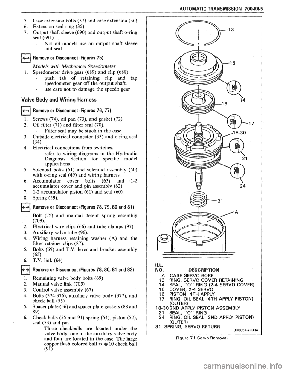
5. Case extension bolts (37)
and case extension (36)
6. Extension seal ring (35)
7. Output
shaft sleeve (690) and output shaft o-ring
seal (691)
- Not all models use an output shaft sleeve
and seal
a Remove or Disconnect (Figures 75)
Models with Mechanical Speedometer
1. Speedometer drive gear
(689) and clip (688)
- push tab of retaining clip and tap
speedometer gear off the output shaft.
- use care not to damage the speedo gear
Valve Body and Wiring Harness
Remove or Disconnect (Figures 76, 77)
1. Screws (74), oil
pan (73), and gasket (72).
2. Oil filter
(71) and filter seal (70).
- Filter seal may be stuck in the case
3. Outside
electrical connector (33) and o-ring seal
(34).
4. Electrical connections from switches.
- refer to wiring diagrams in the Hydraulic
Diagnosis Section for specific model
applications
5. Solenoid bolts
(51) and solenoid assembly (50)
with o-ring seal (49) and wiring harness.
6. Accumulator cover bolts (63) and 1-2
accumulator cover and pin assembly (62).
7. 1-2 accumulator piston (61) and seal (60).
8. Spring (59).
Remove or Disconnect (Figures 78,99,88 and 81)
1. Bolt (75) and manual detent spring assembly
(709).
2. Electrical wire clips (66) and tube clamps (97).
3. Auxiliary valve tube (96).
4. Wiring harness retaining washer (A) and the
filter retainer clips
(87).
5. Bolts (69) and T.V. lever and bracket assembly
(65)
6. T.V. link (64)
Remove or Disconnect (Figures 78,88,8'1 and 82)
1. Remaining valve body bolts (69)
2. Manual valve link (705)
3. Control valve assembly (67)
4. Bolts
(374-376), auxiliary valve body (377), and
check
ball (55)
5. Spacer plate (56) and spacer plate gaskets (88 and
89)
6. Check balls (55 and 91) spring (54), piston (52),
sea1 (53) and pin
- Three checkballs are located under the
valve body, one in the auxiliary valve body
and four are located in the case. The large
copper flash colored ball is
# 10 check ball
(9 1)
ILL.
NO.
A
13 14
15 16
17
DESCBPlPT!ON
CASE SERVO BORE
RING,
SERVO COVER RETAINING
SEAL, "0" RING (2-4 SERVO COVER)
COVER, 2-4 SERVO
PISTON, 4TH APPLY
RING,
OIL SEAL (4TH APPLY PISTON) (OUTER)
18-30 2ND AP'PLY PISTON ASSEMBLY 21 SEAL, "0" RlNG
24 RING, OIL SEAL (2ND APPLY
PISTON)
(OUTER) 31 SPRING, SERVO RETURN JH0057-700R4
Figure 7 1 Servo Removal
Page 1058 of 1825
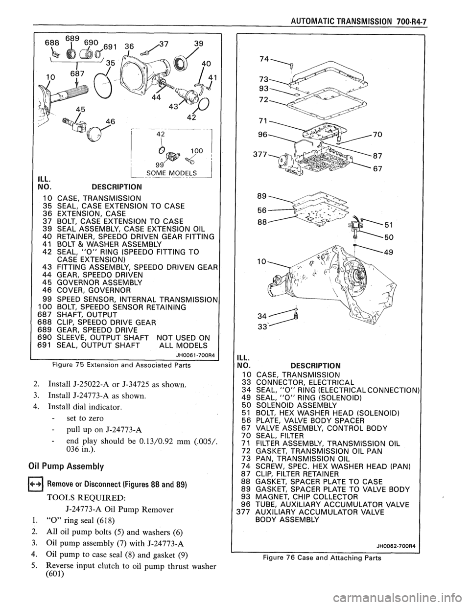
1 SOME MODELS 1 ILL.
NO. DESCRIPTION
10 CASE, TRANSMISSION
1 35 SEAL, CASE EXTENSION TO CASE
36 EXTENSION, CASE
37 BOLT,
CASE EXTENSION TO CASE
39 SEAL ASSEMBLY, CASE EXTENSION OIL
40 RETAINER, SPEEDO
DRIVEN GEAR FITTING
41 BOLT
& WASHER ASSEMBLY
42 SEAL,
"0" RlNG (SPEEDO FITTING TO
CASE EXTENSION)
43 FITTING ASSEMBLY, SPEEDO DRIVEN GEAI
44 GEAR, SPEEDO DRIVEN
45 GOVERNOR ASSEMBLY
46 COVER, GOVERNOR
99 SPEED SENSOR, INTERNAL
TRANSMISSIOI 100 BOLT, SPEEDO SENSOR RETAINING
687 SHAFT, OUTPUT
688 CLIP, SPEEDO DRIVE GEAR
689 GEAR, SPEEDO DRIVE
690 SLEEVE, OUTPUT SHAFT NOT USED ON
691 SEAL, OUTPUT SHAFT ALL MODELS
Figure 75 Extension and Associated Parts
2. Install J-25022-A or J-34725 as shown.
3. Install J-24773-A as shown.
4. Install dial indicator.
- set to zero
- pull up on J-24773-A
- end play should be 0.13/0.92 mm (.005/.
036 in.).
Oil Pump Assembly
Remove or Disconnect (Figures 88 and 89)
TOOLS REQUIRED:
J-24773-A Oil Pump Remover
1. "0" ring seal (6 18)
2.
All oil pump bolts (5) and washers (6)
3.
Oil pump assembly (7) with J-24773-A
4. Oil pump to case seal (8) and gasket (9)
AUTOMATIC TRANSMISSION 700-R4-7
ILL.
NO. DESCRIPTION
10 CASE, TRANSMISSION
33 CONNECTOR, ELECTRICAL
34 SEAL,
"0" RlNG (ELECTRICAL CONNECTION)
49 SEAL,
"0" RlNG (SOLENOID)
50 SOLENOID ASSEMBLY
51 BOLT, HEX WASHER HEAD (SOLENOID)
56 PLATE. VALVE BODY SPACER
/ 67 VALVE' ASSEMBLY, CONTROL BODY
70 SEAL, FILTER
1 71 FILTER ASSEMBLY, TRANSMISSION OIL
72 GASKET, TRANSMISSION OIL PAN
73 PAN, TRANSMISSION OIL
74 SCREW, SPEC. HEX WASHER HEAD (PAN)
87 CLIP, FILTER RETAINER
88 GASKET, SPACER PLATE TO CASE
89 GASKET, SPACER PLATE TO VALVE BODY
93 MAGNET, CHIP COLLECTOR
96 TUBE, AUXILIARY ACCUMULATOR VALVE
377 AUXILIARY ACCUMULATOR VALVE
BODY ASSEMBLY
Figure 76 Case and Attaching Parts
5. Reverse input clutch to oil pump thrust washer
(60 1)