low beam PONTIAC FIERO 1988 Service User Guide
[x] Cancel search | Manufacturer: PONTIAC, Model Year: 1988, Model line: FIERO, Model: PONTIAC FIERO 1988Pages: 1825, PDF Size: 99.44 MB
Page 1451 of 1825
HEADLIGHTS
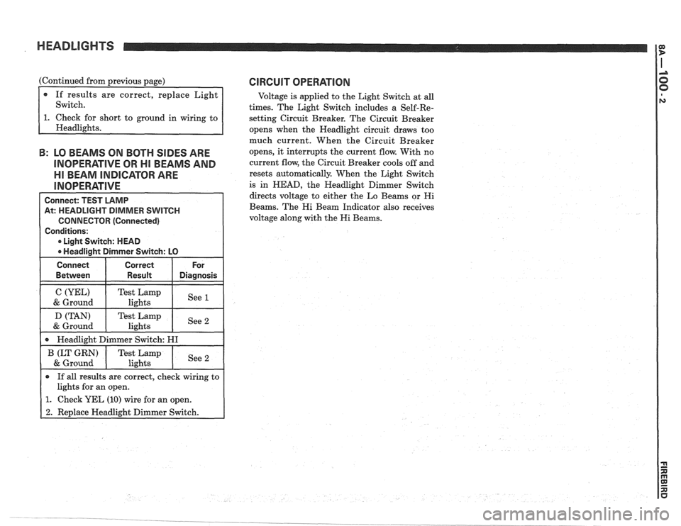
(Continued from previous page)
If results are correct, replace Light
Switch.
short to ground in wiring to
B: LO BEAMS ON BOTH SIDES ARE
INOPERATIVE OR HI BEAMS AND
Ell BEAM INDICATOR ARE
Connect: TEST LAMP
At: HEADLIGHT DIMMER SWITCH
CONNECTOR (Connected)
Conditions:
0 Light Switch: HEAD
0 Headlight Dimmer Switch: LO
Connect Correct For
0 If all results are correct, check wiring to
lights for an open.
1. Check YEL (10) wire for an open.
2. Replace Headlight Dimmer Switch.
CIRCUIT OPERATION
Voltage is applied to the Light Switch at all
times. The Light Switch includes a Self-Re-
setting Circuit Breaker. The Circuit Breaker
opens when the Headlight circuit draws too
much current. When the Circuit Breaker
opens, it interrupts the current flow. With no
current flow, the Circuit Breaker cools off and
resets automatically. When the Light Switch
is in
HEAD, the Headlight Dimmer Switch
directs voltage to either the Lo Beams or
Hi
Beams. The Hi Beam Indicator also receives
voltage along with the
Hi Beams.
Page 1462 of 1825
HEADLIGHTS WITH LAMP MONITOR
TROUBLESHOOTING HINTS
r Try the following checks before doing the
System Diagnosis.
1. If the Headlight on one side is dimly lit, check
the ground on that side.
2. If the Hi Beam Indicator does not light, but
the High Beams operate, check the LT GRN
(11) wire for an open (see schematic).
3. If one Headlight doesn't work, check the con-
nections, the Headlight, and the wires to the
Headlight.
4. If the Headlights do not turn off, replace the
Light Switch.
Go to the System Diagnosis for diagnostic
tests.
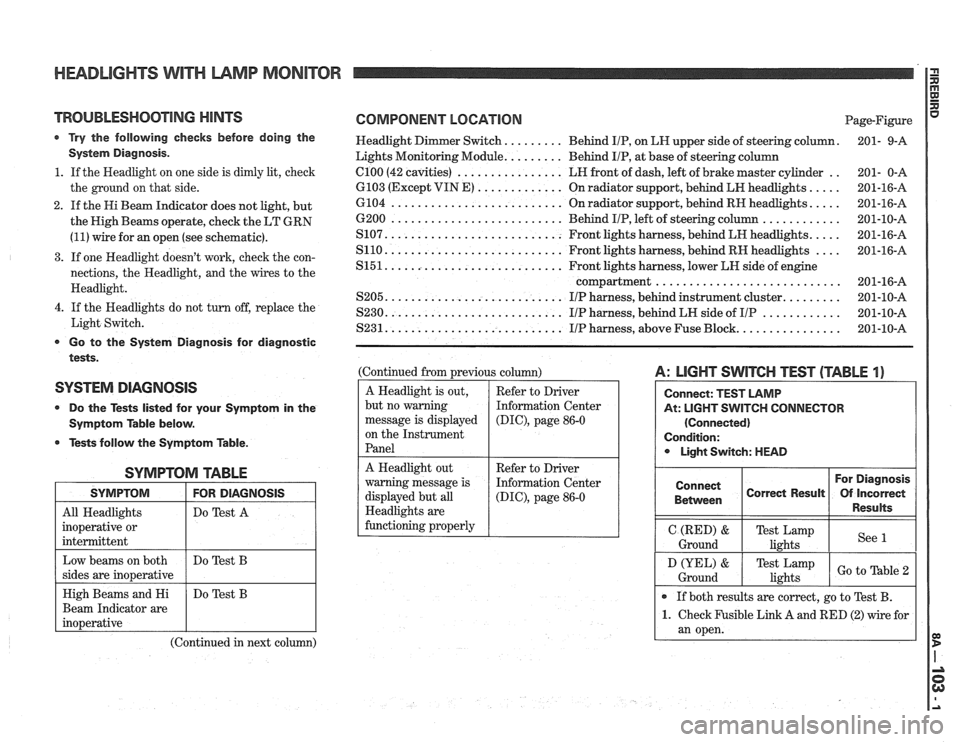
SYSTEM DIAGNOSIS
0 Do the Tests listed for your Symptom in the
Symptom Table below.
@ Tests follow the Symptom Table.
SYMPTOM TABLE
I SYMPTOM I FOR DIAGNOSIS I
All Headlights
inoperative or
intermittent Do
Test A
Beam Indicator are
(Continued in next column)
COMPONENT LOCATION Page-Figure
Headlight Dimmer Switch.
........ Behind IIP, on LH upper side of steering column. 201-
9-A
Lights Monitoring Module.
........ Behind IIP, at base of steering column
.. el00 (42 cavities) ................ LH front of dash, left of brake master cylinder
201- 0-A
.... 6103 (Except VIN E) ............. On radiator support, behind LH headlights.
201-16-A
.... 6104 .......................... On radiator support, behind RH headlights.
201-16-A
............ 6200 .......................... Behind IIP, left of steering column
201-10-A
.... S107. .......................... Front lights harness, behind LH headlights.
201-16-A
.... S110. .......................... Front lights harness, behind RH headlights
201-16-A
S151. .......................... Front lights harness, lower LH side of engine
compartment
............................ 201-16-A
........ S205. .......................... IIP harness, behind instrument cluster. 201-10-A
............ S230. .......................... IIP harness, behind LH side of IIP 201-10-A
............... S231. .......................... IIP harness, above Fuse Block. 201-10-A
(Continued from previous column)
A Headlight is out,
but no warning
message is displayed
on the Instrument
Panel
A: LIGHT SWITCH TEST (TABLE 1)
At: LIGHT SWITCH CONNECTOR
(Connected)
Condition: Light Switch: HEAD
Refer to Driver
Information Center
(DIC), page 86-0
A Headlight out
warning message is
displayed but all
Headlights are
functioning properly For Diagnosis
Connect
Correct Result Of Incorrect
1 Between 1 1 Results 1
Refer to Driver
Information Center
(DIG), page 86-0
I Ground (RED) I Te;ik,",mp I see 1 I
If both results are correct, go to Test B.
1. Check Fusible Link A and RED (2) wire for
an open.
D (YEL) &
Ground Test Lamp
lights Go to able
Page 1463 of 1825
HEADLIGHTS WITH LAMP MONITOR
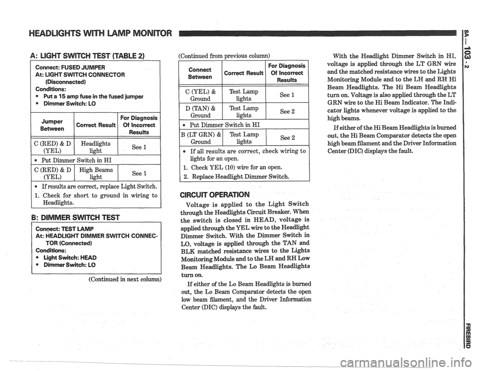
A: LIGHT SWITCH TEST (TABLE 2) (Continued from previous column)
With the Headlight D er
Switch in HI,
Connect: FUSED JUMPER
At: LIGHT
SWITCH CONNECTOR
(Disconnected)
Conditions:
@ Put a 15 amp fuse in the fused jumper
@ Dimmer Switch: LO
( C (RED) & D ( Headlights 1 See (YEL) light I
Jumper
Betvveen
I Put Dimmer Switch in HI I
Correct Result
I 0 If results are correct, replace Light Switch. I
For Diagnosis
Of incorrect
Results
C (RED) & D
(YEL)
1. Check for short to ground in wiring to
I Headlights.
B: DIMMER SWITCH TEST
High Beams
light
Connect: TEST LAMP
At: HEADLIGHT DIMMER SWITCH
COIUNEC-
TOR (Connected)
Conditions: Light Switch: HEAD
@ Dirnmer Switch: LO
See 1
(Continued in next column)
For Diagnosis
Correct
~esu~t Of incorred
1 1 1 Resd% 1
C(YEL)& TestLamp
Ground lights See 1
Ground I
Put
Dimmer Switch in HI
B (LT GRN)
& Test Lamp
lights See 2 Ground
If all results are correct, check wiring to
lights for an open.
1. Check YEL (10) wire for an open.
2. Replace Headlight Dimmer Switch.
CIRCUIT OPERATION
Voltage is applied to the Light Switch
through the Headlights Circuit Breaker. When
the switch is closed in HEAD, voltage is
applied through the YEL wire to the Headlight
Dimmer Switch. With the
D
LO, voltage is applied through the TAN and
BLK matched resistance wires to the Lights
Monitoring Module and to the LH and RH Low
Beam Headlights. The Lo Beam Headlights
turn on.
If either of the Lo Beam Headlights is burned
out, the Lo Beam Comparator detects the open
low beam filament, and the Driver Information
Center (DIC) displays the fault. voltage
is applied through the
LT GRN wire
and the matched resistance wires to the Lights
Monitoring Module and to the LH and
RH Hi
Beam Headlights. The Hi Beam Headlights
turn on. Voltage is also applied through the LT
GRN wire to the Hi Beam
In&cator. The In&-
cator lights whenever voltage is applied to the
high beams.
If either of the Hi Beam Headlights
is burned
out, the Hi Beam Comparator detects the open
high beam filament and the Driver Information
Center (DIC) displays the fault.
Page 1600 of 1825
LIGHTING SYSTEMS AND HORNS 8B-I
SECTION 8B
NG SYSTEMS AND HORNS
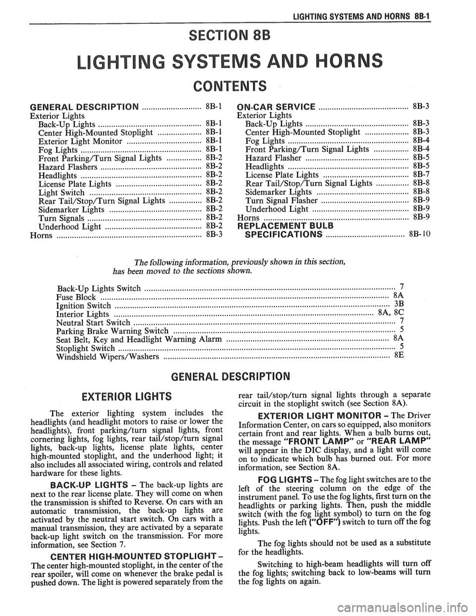
CONTENTS
........................... GENERAL DESCRIPTION 8B-1
Exterior Lights
....................... ................... Back-up Lights .. 8B- 1
Center High-Mounted Stoplight .................... 8B-1
Exterior Light Monitor .................................. 8B-1
............................ .................... Fog Lights .. 8B-1
Front Parking/Turn Signal Lights ................ 8B-2
............................... Hazard Flashers .. ........ 8B-2 .................................................... Headlights 8B-2
License Plate Lights ..................................... 8B-2
Light Switch ............................................... 8B-2
............... Rear Tail/Stop/Turn Signal Lights 8B-2
Sidemarker Lights ........................................ 8B-2
Turn Signals .......................................... 8B-2
......................... Underhood Light ... ........ 8B-2
Horns .......................................................... 8B-3
....................................... ON-CAR SERVICE 8B-3
Exterior Lights
............................................. Back-up Lights 8B-3
Center High-Mounted Stoplight .................... 8B-3
Fog Lights .................................................... 8B-4
Front Parking/Turn Signal Lights ................ 8B-4
Hazard Flasher .............................................. 8B-5
....................................................... Headlights 8B-5
License Plate Lights ..................................... 8B-7
............... Rear Tail/Stop/Turn Signal Lights 8B-8
.......................................... Sidemarker Lights 8B-8
................... ............... Turn Signal Flasher .. 8B-9
......................................... Underhood Light 8B-9
Horns ................................................................. 8B-9
REPLACEMENT BULB
.................................... SPECIFICATIONS 8B- 10
The following information, previously shown in this section,
has been moved to the sections shown.
Back-up Lights Switch
............................. ... ............................................................................ 7
................................................................................................................................. Fuse Block 8A
Ignition Switch ........................................................................................................................... 3B
Interior Lights
................................................................................................................... 8A, 8C
Neutral Start Switch ..................................................................................................................... 7
Parking Brake Warning Switch
......................... ... .................................................................... 5
........................................................................ Seat Belt, Key and Headlight Warning Alarm 8A
Stoplight Switch .......................... .. ............................................................................................... 5
Windshield
Wipers/Washers .................................................................................................... 8E
GENERAL DESCRIPTION
The exterior lighting system includes the
headlights (and headlight motors to raise or lower the
headlights), front
parkinghurn signal lights, front
cornering lights, fog lights, rear
tail/stop/turn signal
lights, back-up lights, license plate lights, center
high-mounted stoplight, and the underhood light; it
also includes all associated wiring, controls and related
hardware for these lights.
BACK-UP LIGHTS - The back-up lights are
next to the rear license plate. They will come on when
the transmission is shifted to Reverse. On cars with an
automatic transmission, the back-up lights are
activated by the neutral start switch. On cars with a
manual transmission, they are activated by a separate
back-up light switch on the transmission. For more
information, see Section 7.
CENTER HIGH-MOUNTED STOPLIGHT-
The center high-mounted stoplight, in the center of the
rear spoiler, will come on whenever the brake pedal is
pushed down. The light is powered separately from the rear
tail/stop/turn signal
lights through a separate
circuit in the stoplight switch (see Section
8A).
EXTERIOR LIGHT MONITOR - The Driver
Information Center, on cars so equipped, also monitors
certain front and rear lights. When a bulb burns out,
the message
"FRONT LAMP" or "REAR LAMP"
will appear in the DIC display, and a light will come
on to indicate which bulb has burned out. For more
information, see Section
8A.
FOG LIGHTS -The fog light switches are to the
left of the steering column on the edge of the
instrument panel. To use the fog lights, first turn on the
headlights or parking lights. Then, push the middle
switch (with the fog light symbol) to turn on the fog
lights. Push the left
("OFF") switch to turn off the fog
lights.
The fog lights should not be used as a substitute
for the headlights.
Switching to high-beam headlights will turn off
the fog lights; switching back to low-beams will turn
the fog lights on again.
Page 1601 of 1825
88-2 LIGHTING SYSTEMS AND HORNS
The fog lights must be aimed for proper
illumination of the road. Fog light
aim should be
checked: at least once a year; when a new light housing
is installed; or if service or repairs in the front end area
have (or may have) disturbed the fog light mountings.
FRONT PARKING/TURM SIGNAL
LIGHTS - Pushing either side of the instrument panel
switch will turn on the front parking lights. (Pushing
the left side of the switch will also turn on the
headlights.) When the ignition is on and the turn signal
lever is moved, the appropriate front parking light
flashes to signal a turn. Both lights will flash when the
hazard flashers are on.
If the driver's door is opened when the parking
lights are on, a warning tone will sound. For more
information, see Section
8A-77.
HAZARD FLASHERS - The hazard warning
flasher is part of the turn signal circuit. Pushing in the
button (on the right side of the steering column) will
cause the front and rear turn signal lights, and the front
sidemarker lights, to flash. Pull out the collar around
the button to turn off the hazard flashers.
The hazard flashers will work with the ignition
either off or on. When the hazard flashers are on, the
turn signals do not
work.
The hazard flashers will stop flashing and stay on
brightly if the brake pedal is pushed down.
HEADLIGHTS - The headlights are controlled
by the switch on the instrument panel (to the left of the
speedometer). They will come on whether or not the
ignition is turned on. Pushing the upper left side of the
switch turns on the headlights and causes the headlight
motors to raise the headlights. Pushing the bottom part
of the switch turns off the headlights, and they should
lower.
If the driver's door is opened when the ignition
is off and the headlights are on, a warning tone will
sound. For more information, see Section
8A-77.
Headlight low-beam and high-beam are
controlled by the turn
signal/multifunction lever on
the left side of the steering column. When the
headlights are on, pull the lever toward the steering
wheel until the switch clicks; the lights will change
from low-beam to high-beam, or from high-beam to
low-beam. An indicator light on the center instrument
cluster will come on when the high-beam headlights
are on.
The headlights must be aimed for proper
illumination of the road. Headlight aim should be
checked: at least once a year; when a new headlight
bulb is installed; or if service or repairs in the front end
area have (or may have) disturbed the headlights or
their mountings. The headlight bezels do not need to
be removed to aim the headlights.
Headlight focus is set when the sealed-beam unit
is made; no adjustment for focus is necessary or
possible.
Some state and local laws specify
requirements for headlight aim; these laws
must be followed.
LICENSE PLATE LBGHTS -A light above the
rear license plate will come on when the headlights or
parking lights are on.
LIGHT SWITCH - Most exterior lights are
controlled by the switch on the instrument panel, to the
left of the speedometer. Pushing the upper right part
of the switch turns on the front parking lights, the
taillights and the sidemarker lights. (It also turns on
the instrument panel lights.) Pushing the upper left
part of the switch turns on all these lights plus the
headlights. Pushing the bottom part of the switch turns
off all lights.
In some cases (such as going through a car wash),
it may be desirable to raise the headlights without
leaving the headlights on. To do so, push the upper
right part of the switch to turn on the parking lights.
Then, lightly push the upper right part of the switch;
the headlights will raise but will not turn on.
(Remember that the parking lights and taillights will
stay on.)
For more information on this switch (including
on-car service), see Section
8C. Also see Section 8C for
information on interior lights.
REAR TAlL/STOP/TURN SIGNAL
LIGHTS - The rear tail/stop/turn signal lights are
part of the same light assembly. Pushing either side of
the instrument panel switch turns on the taillights.
When the brake pedal is pushed down, the lights glow
brighter to serve as stoplights.
Moving the turn signal lever when the ignition is
on causes the appropriate rear lights to flash. (If the
brake pedal is held down and a turn is signalled, one
side will flash and the other will stay on brightly.)
All lights will flash when the hazard flashers are
on. However, if the brake pedal is pushed while the
hazard flashers are on, the lights will stop flashing and
stay on brightly.
SIDEMARKER LIGHTS -The front and rear
sidemarker lights will come on when the headlights or
parking lights are on. Both front and rear sidemarker
lights also have reflectors; they will shine when struck
by light, whether or not the car's lights are on.
If the headlights or parking lights are off when a
turn is signalled, the front sidemarker light will flash
in unison with the front turn signal light on the same
side. If the lights are on when a turn is signalled, the
front
sidemarker light and front turn signal light flash
alternately.
TURN SlG N ALS - The front turn signals are
combined with the front parking lights. The rear turn
signals are part of the rear
tail/stop/turn signal lights.
The turn signals work only when the ignition is on, and
the hazard flashers are turned off.
The turn signals are controlled by the turn
signal/multifunction lever on the left side of the
steering column. Moving the lever all the way up or
down (past the detent) will turn on the turn signals.
When the turn is completed, the lever will return to
neutral and the turn signals will stop flashing.
For changing lanes or shallow turns where the
steering wheel does not move far enough to cancel the
signal, move the turn signal lever only to the first
detent. When the lever is released, it will return to
neutral and the turn signals will cancel.
UNDERHOOD LIGHT - The underhood light
will come on when the hood is raised.
Page 1605 of 1825
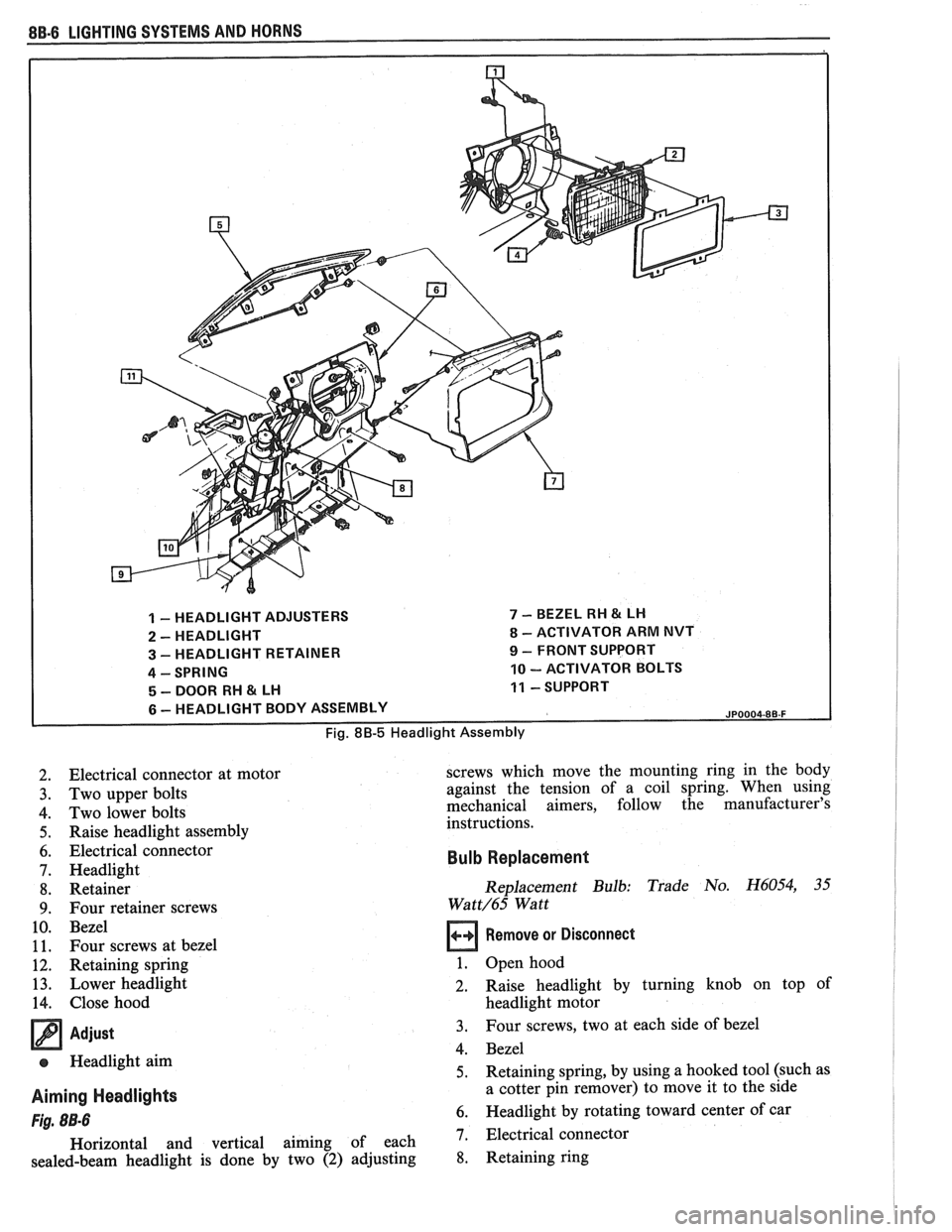
1 - HEADLIGHT ADJUSTERS 7 - BEZEL RH & LH
2 - HEADLIGHT 8 - ACTIVATOR ARM NVT
3 - HEADLIGHT RETAINER 9 - FRONT SUPPORT
4 - SPRING 10 - ACTIVATOR BOLTS
5 - DOOR RH 81 LH 11 - SUPPORT
6 - HEADLIGHT BODY ASSEMBLY JP0004-8B-F
Electrical connector at motor
Two upper bolts
Two lower bolts
Raise headlight assembly
Electrical connector
Headlight Retainer
Four retainer screws
Bezel
Four screws at bezel
Retaining spring Lower headlight
Close hood
Adjust
e Headlight aim
Aiming Headlights
Fig. 8B-6
Horizontal and vertical aiming of each
sealed-beam headlight is done by two
(2) adjusting screws
which move the mounting ring in the body
against the tension of a coil spring. When using
mechanical aimers, follow the manufacturer's
instructions.
Bulb Replacement
Replacement Bulb: Trade No. H6054, 35
Wa t
t/65 Watt
Remove or Disconnect
1. Open hood
2. Raise headlight by turning knob on top of
headlight motor
3. Four screws, two at each side of bezel
4. Bezel
5. Retaining spring, by using a hooked tool (such as
a cotter pin remover) to move it to the side
6. Headlight by rotating toward center of car
7. Electrical connector
8. Retaining ring
Page 1666 of 1825
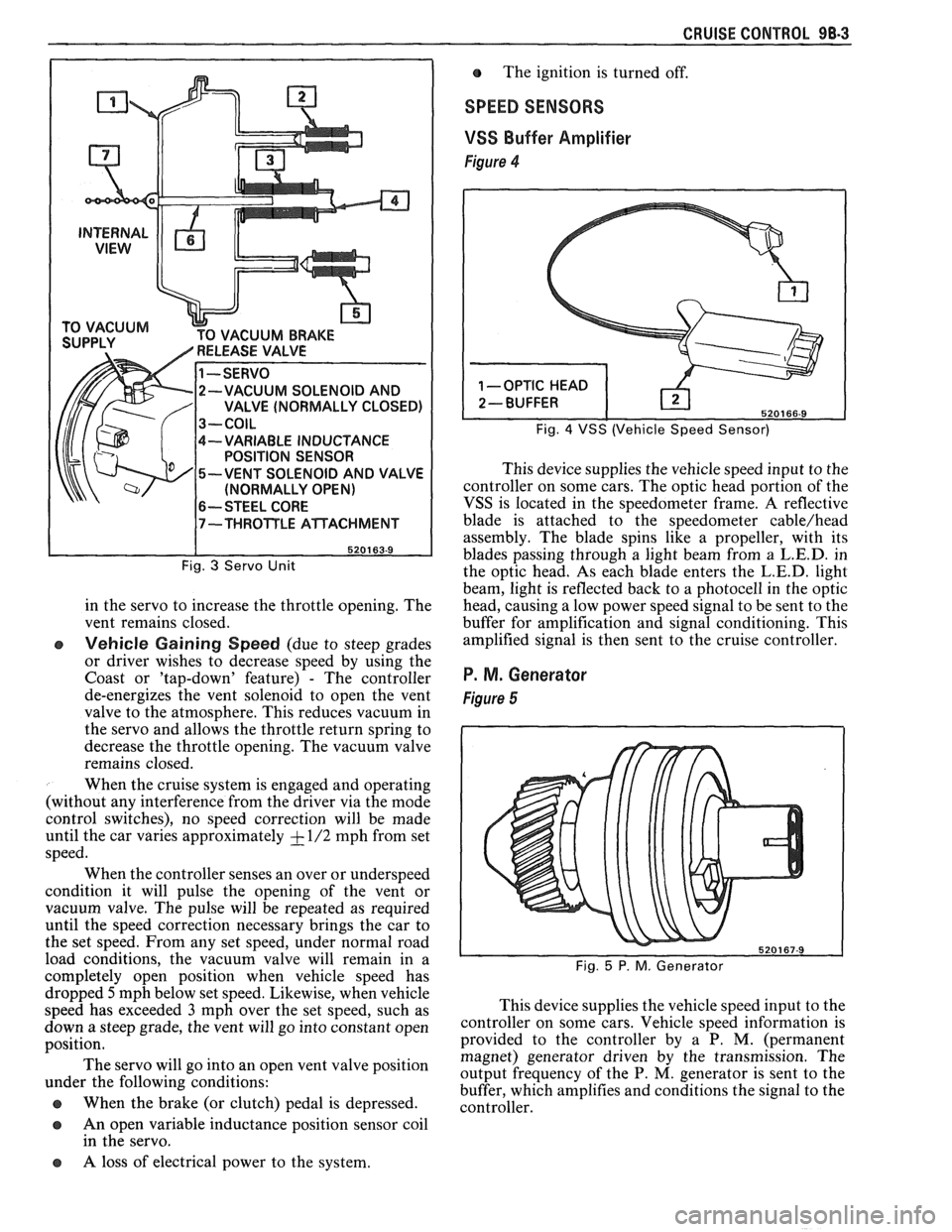
CRUISE CONTROL 98-3
CUUM BRAKE
-VARIABLE INDUCTANCE
POSITION SENSOR
-VENT SOLENOID AND VALVE
(NORMALLY OPEN)
6-- STEEL CORE
Fig. 3 Servo Unit
in the servo to increase the throttle opening. The
vent remains closed.
e Vehicle Gaining Speed (due to steep grades
or driver wishes to decrease speed by using the
Coast or 'tap-down' feature)
- The controller
de-energizes the vent solenoid to open the vent
valve to the atmosphere. This reduces vacuum in
the servo and allows the throttle return spring to
decrease the throttle opening. The vacuum valve
remains closed.
When the cruise system is engaged and operating
(without any interference from the driver via the mode
control switches), no speed correction will be made
until the car varies approximately
+ - 1/2 mph from set
speed.
When the controller senses an over or underspeed
condition it will pulse the opening of the vent or
vacuum valve. The pulse will be repeated as required
until the speed correction necessary brings the car to
the set speed. From any set speed, under normal road
load conditions, the vacuum valve will remain in a
completely open position when vehicle speed has The
ignition is turned off.
SPEED SENSORS
VSS
Buffer Amplifier
Figure 4
Fig. 4 VSS (Vehicle Speed Sensor)
This device supplies the vehicle speed input to the
controller on some cars. The optic head portion of the
VSS is located in the speedometer frame. A reflective
blade is attached to the speedometer
cable/head
assembly. The blade spins like a propeller, with its
blades passing through a light beam from a
L.E.D. in
the optic head. As each blade enters the
L.E.D. light
beam, light is reflected back to a photocell in the optic
head, causing a low power speed signal to be sent to the
buffer for amplification and signal conditioning. This
amplified signal is then sent to the cruise controller.
P. M. Generator
Figure 5
dropped 5mph below set speed. Likewise, when vehicle
speed has exceeded
3 mph over the set speed, such as This
device supplies the vehicle speed input to the
down a steep grade, the vent will go into ,-onstant open ~0ntI-011er on some cars. Vehicle speed information is
position. provided
to the controller by a P. M. (permanent
magnet) generator driven by the transmission. The
The servo go into an 'Pen vent position output frequency of the P. M, generator is sent to the under the following conditions:
buffer, which amplifies and conditions the signal to the
@ When the brake (or clutch) pedal is depressed. controller.
a An open variable inductance position sensor coil
in the servo.
a A loss of electrical power to the system.