door lock PONTIAC FIERO 1988 Service Owner's Manual
[x] Cancel search | Manufacturer: PONTIAC, Model Year: 1988, Model line: FIERO, Model: PONTIAC FIERO 1988Pages: 1825, PDF Size: 99.44 MB
Page 1493 of 1825
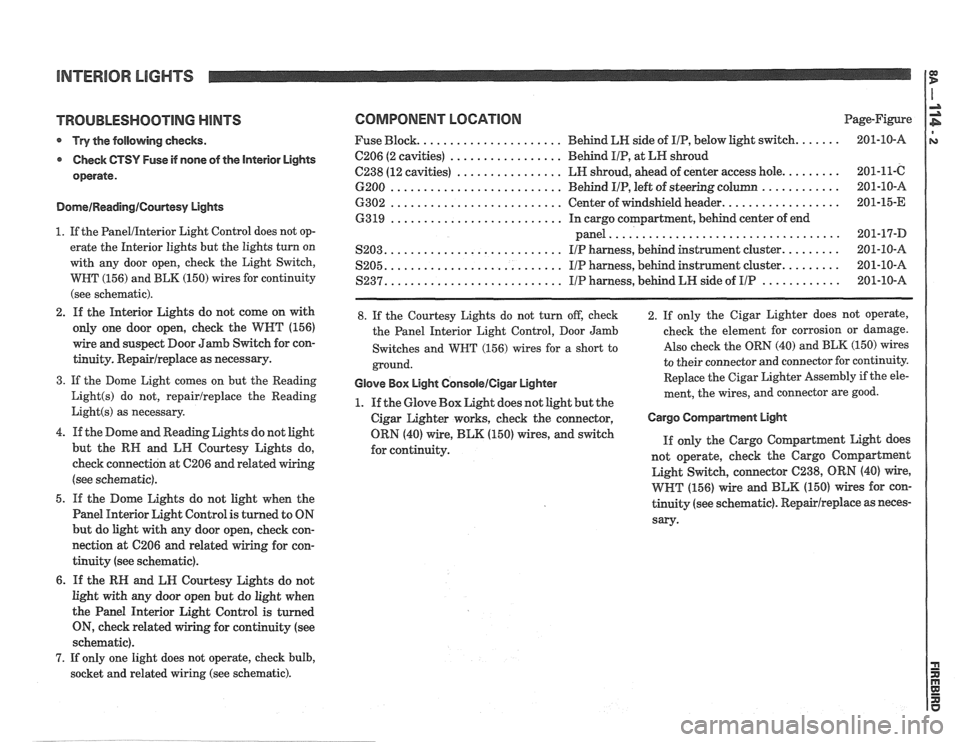
TROUBLESHOOTING HINTS
* Try the following checks.
Check
GTSY Fuse if none of the Interior Lights
operate.
DomeIReadinglCourtesy Lights
1. If the PanelIInterior Light Control does not op-
erate the Interior lights but the lights turn on
with any door open, check the Light Switch,
WBT (156) and BLK (150) wires for continuity
(see schematic).
2. If the Interior Lights do not come on with
only one door open, check the
WNT (156)
wire and suspect Door Jamb Switch for con-
tinuity.
Repairlreplace as necessary.
3. If the Dome Light comes on but the Reading
Light(s) do not, repairlreplace the Reading
Light(s) as necessary.
4. If the Dome and Reading Lights do not light
but the
RN and LII Courtesy Lights do,
check connection at
C206 and related wiring
(see schematic).
5. If the Dome Lights do not light when the
Panel Interior Light Control is turned to ON
but do light with any door open, check con-
nection at 6206
and related wiring for con-
tinuity (see schematic).
6. If the RN and LN Courtesy Lights do not
light with any door open but do light when
the Panel Interior Light Control is turned
ON, check related wiring for continuity (see
schematic).
7. If only one light does not operate, check bulb,
socket and related wiring (see schematic).
COMPONENT LOCATION Page-Figure
..................... Fuse Block. Behind
LN side of IIP, below light switch. ...... 201-10-A
................. C206 (2 cavities) Behd IIP, at LH shroud
................ C238 (12 cavities) LH shroud, ahead of center access hole. ........ 201-11-C
.......................... ............ 6200 Behind IIP, left of steering column 201-10-A
.......................... ................. 6302 Center of windshield header. 201-15-E
.......................... 63 19 In cargo compartment, behind center of end
................................... panel 201-17-D
.......................... S203. IIP harness, behind instrument cluster. ........ 201-10-A
.......................... S205. IIP harness, behind instrument cluster. ........ 201-10-A
.......................... ............ S237. I/P harness, behind LH side of IIP 201-10-A
8. If the Courtesy Lights do not turn off, check
the Panel Interior Light Control, Door Jamb
Switches and
WBT (156) wires for a short to
ground.
Glove Box Light GonsoleICigar Lighter
1. If the Glove Box Light does not light but the
Cigar Lighter works, check the connector,
ORN (40) wire,
BLK (150) wires, and switch
for continuity. 2. If
only the Cigar Lighter does not operate,
check the element for corrosion or damage.
Also check the ORN (40) and BLK (150) wires
to their connector and connector for continuity.
Replace the Cigar Lighter
Assembly if the ele-
ment, the wires, and connector are good.
Cargo Compartment EIgM
If only the Cargo Coqartment Light does
not operate, check the Cargo
Coqartment
Light Switch, connector 6238, ORN (40) wire,
WHT (156) wire and BLK (150) wires for con-
tinuity (see schematic).
Repairlreplace as neces-
sary-
Page 1504 of 1825
POWER WINDOWS
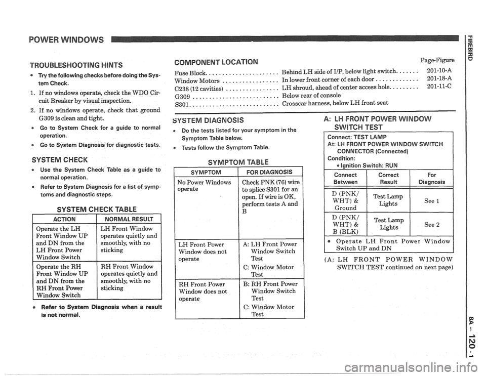
TROUBLESHOOTING HINTS
s Try the following checks before doing the Sys-
tem Check.
1. If no windows operate, check the WDO Cir-
cuit Breaker by visual inspection.
2. If no windows operate, check that ground
6309 is clean and tight.
e Go to System Check for a guide to normal
operation.
e Go to System Diagnosis for diagnostic tests.
COMPONENT LOCNIOM Page-Figure
..................... ...... Fuse Block. Behind LH side
of IIP, below light switch. 201-10-A
................. ............. VVindow Motors In lower front corner of each door 201-18-A
................ ........ C238 (12 cavities) LH shroud, ahead of center access hole. 201-11-C
.......................... 6309 Below rear of console
.......................... S301. Crosscar harness, below LR front seat
SYSTEM DIAGNOSIS A: LH FRONT POWER WINDOW
e Do the tests listed for your symptom in the SWITCH TEST
Symptom Table below.
e Tests follow the Symptom Table.
SYSTEM CHECK SYMPTOM TABLE
* Use the System Check Table as a guide to
normal operation.
Refer to System Diagnosis for a list of symp-
toms and diagnostic steps.
SYSTEM CHECK TABLE
and DN from the
moothly, with no
EH Front Power
Window Switch
RH Front Window
RH Front Power
r Refer to System Diagnosis when a result
is not normal.
to splice S301 for an
open. If wire is OK,
perform tests A and
RH Front Power
Window does not Window Switch
CONNECTOR (Connected)
(A: LN FRONT POWER WINDOW
SWITCH TEST continued on next page)
Page 1507 of 1825
x POWER DOOR LOCKS I $
DEFOGGER
Page 1508 of 1825
POWER DOOR LOCKS
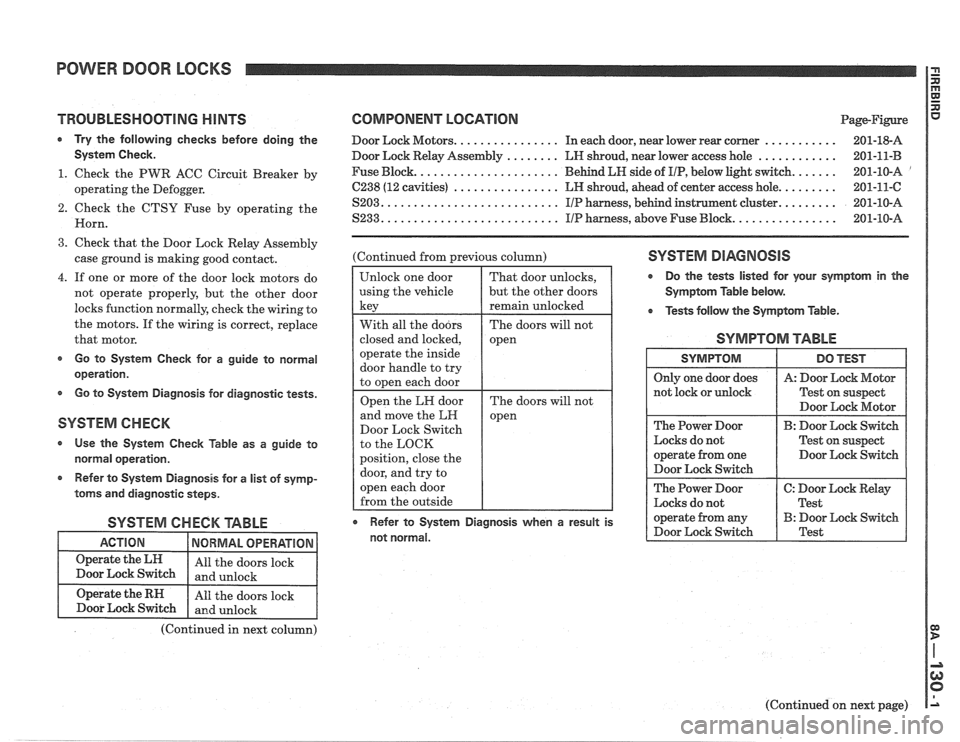
TROUBLESHOOTING HINTS
Try the following checks before doing the
Systern Check.
1. Check the PWR ACC Circuit Breaker by
operating the Defogger.
2. Check the CTSY Fuse by operating the
Horn.
3. Check that the Door Lock Relay Assembly
case ground is making good contact.
4. If one or more of the door lock motors do
not operate properly, but the other door
locks function normally, check the wiring to
the motors. If the wiring is correct, replace
that motor.
s Go to System Check for a guide to normal
operation.
Go to System Diagnosis for diagnostic tests.
SYSTEM CHECK
Use the System Check Table as a guide to
normal operation.
r Refer to System Diagnosis for a list of symp-
toms and diagnostic steps.
SYSTEM CHECK TABLE
COMPONENT LOCATION Page-Rgure
Door Lock Motors. ............... In each door, near lower rear corner ........... 201-18-A
Door Lock Relay Assembly
........ LN shroud, near lower access hole ............ 201-11-B
Fuse Block. ..................... Behind LH side of IIP, below light switch. ...... 201-10-A '
C238 (12 cavities) ................ LH shroud, ahead of center access hole. ........ 201-11-C
S203. .......................... IIP harness, behind instrument cluster. ........ 201-10-A
S233. .......................... IIP harness, above Fuse Block. ............... 201-10-A
(Continued from previous column)
Door Lock Switch
to the LOCK
position, close the SYSTEM DIAGNOSIS
r Do the tests listed for your symptom in the
Symptom Table below.
Tests
follow the Symptom Table.
SYMPTOM TABLE
Test on suspect
Door Lock Motor
The Power Door
B: Door Lock Switch
Locks do not Test on suspect
operate from one Door Lock Switch
Door Lock Switch
The Power Door
C: Door Lock Relay
Locks do not
I Test
r Refer to System Diagnosis when a result is operate from any B: Door Lock Switch
not normal. Door
Lock Switch Test
(Continued in next column)
(Continued on next page)
Page 1509 of 1825
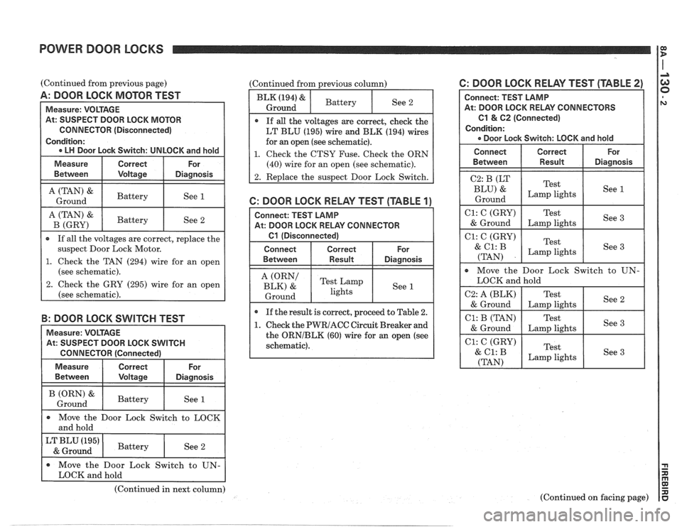
POWER DOOR LOCKS
IT
(Continued from previous page)
A: DOOR LOCK MOTOR TEST
At: SUSPECT DOOR LOCK MOTOR
CONNECTOR (Disconnected)
suspect Door Lock Motor.
1. Check the TAN (294) wire for an open
(see schematic).
2. Check the GRY (295) wire for an open
B: DOOR LOCK SWITCH TEST
(Continued from previous column)
See 2
If
all the voltages are correct, check the
LT BLU (195) wire and BLK (194) wires
for an open (see schematic).
1. Check the CTSU Fuse. Check the ORN
6: DOOR LOCK RELAY TEST [TABLE '11
Connect: TEST LAMP
At: DOOR LOCK RELAY CONNECTOR
61 (Disconnected)
A (ORN' Test Lamp
BLK) & See 1
1 Ground 1 lights
If the result is correct, proceed to Table 2.
1. Check the PWRIACC Circuit Breaker and
the
ORNIBLK (60) wire for an open (see
schematic).
(Continued in next column)
6: DOOR LOCK RELAY TEST (TABLE 2)
Connect: TEST LAMP
At: DOOR LOCK RELAY CONNECTORS
C1 & 62 (Connected)
Condition: Door Lock Switch: LOCK and hold
Move the Door Lock Switch to UN-
I LOCK and hold
C1: C (GRY)
Test See
3
(Continued on facing page)
Page 1510 of 1825
POWER DOOR LOCKS
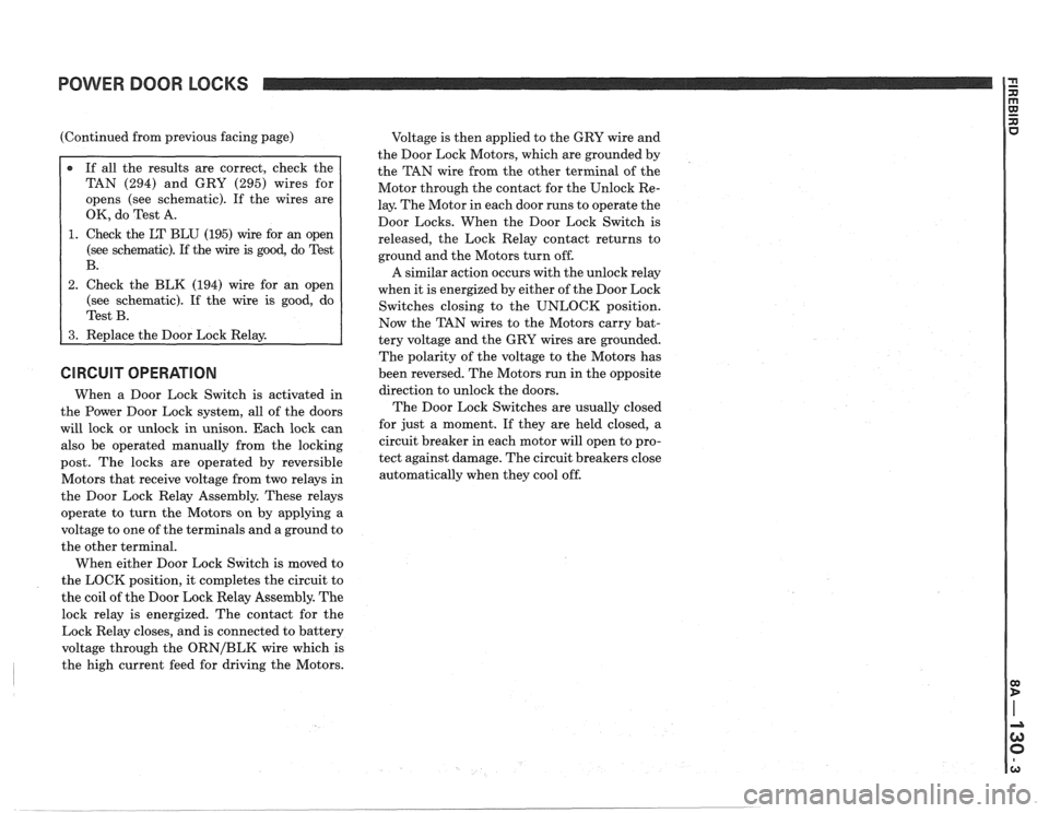
(Continued from previous facing page)
TAN (294) and GRY (295) wires for
opens (see schematic). If the wires are
OK, do Test A.
1. Check the LT BLU (195) wire for an open
(see schematic). If the
wire is good, do Test
2. Check the BLK (194) wire for an open
(see schematic). If the wire is good, do
CIRCUIT OPERATION
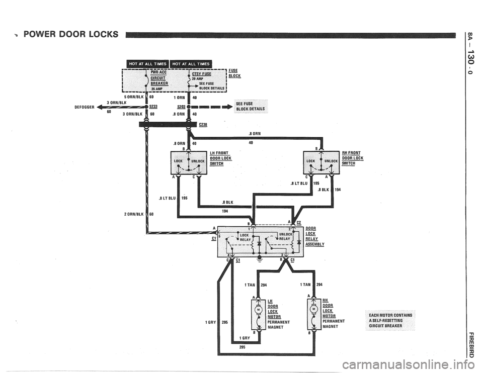
When a Door Lock Switch is activated in
the Power Door Lock system, all of the doors
will lock or unlock in unison. Each lock can
also be operated manually from the locking
post. The locks are operated by reversible
Motors that receive voltage from two relays in
the Door Lock Relay Assembly. These relays
operate to turn the Motors on by applying a
voltage to one of the terminals and a ground to
the other terminal.
When either Door Lock Switch is moved to
the LOCK position, it completes the circuit to
the coil of the Door Lock Relay Assembly. The
lock relay is energized. The contact for the
Lock Relay closes, and is connected to battery
voltage through the
ORNIBLK wire which is
the high current feed for driving the Motors. Voltage
is then applied to the GRY wire and
the Door Lock Motors, which are grounded by
the TAN wire from the other terminal of the
Motor through the contact for the Unlock Re-
lay. The Motor in each door runs to operate the
Door Locks. When the Door Lock Switch is
released, the Lock Relay contact returns to
ground and the Motors turn off.
A similar action occurs with the unlock relay
when it is energized by either of the Door Lock
Switches closing to the UNLOCK position.
Now the TAN wires to the Motors carry bat-
tery voltage and the GRY wires are grounded.
The polarity of the voltage to the Motors has
been reversed. The Motors run in the opposite
direction to unlock the doors.
The Door Lock Switches are usually closed
for just a moment. If they are held closed, a
circuit breaker in each motor will open to pro-
tect against damage. The circuit breakers close
automatically when they cool off.
Page 1583 of 1825
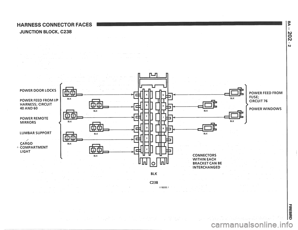
HARNESS CONNECTOR FACES
JUNCTION BLOCK, 6238
POWER DOOR LOCKS
POWER FEED FROM
IIP
HARNESS; CIRCUIT
40 AND 60
POWER REMOTE
MIRRORS
LUMBAR SUPPORT
CARGO
COMPARTMENT LIGHT CONNECTORS
WITHIN EACH
BRACKET CAN BE
INTERCHANGED
BLK POWER
FEED FROM
FUSE;
CIRCUIT
76
POWER WINDOWS
Page 1614 of 1825
INSTRUMENT PANEL. GAGES & CONSOLE 8C-3
tank only when ignition switch is turned to "ON" or
"ACCESSORY" positions.
When ignition is turned to "OFF" or "START"
positions, the pointer may come to rest at any position.
The letters
"E" and "F" on the fuel gage are used to
point out direction of indicator travel only.
TEMPERATURE WARNING LIGHT
The engine temperature warning light is
controlled by a thermal switch which senses engine
coolant temperatures.
When the ignition switch is turned to "START"
position, a test circuit is closed and the light will come
on to indicate whether the light is functioning properly.
It is important to note that with low boiling-point
coolants (such as plain water) the temperature light
may not come on even though the coolant is boiling.
GENERATOR WARNING LIGHT
The generator warning light, located in the
instrument cluster, should come on when the ignition
switch is turned
"ON" and engine is not running. If
not, either the bulb is burned out or wiring to generator
has an open circuit.
When the generator voltage output becomes
greater than the battery voltage, the
"GEN" light
should go out. This does not, however, indicate
whether the battery is being charged or if the voltage
regulator is functioning properly.
Checks of the charging system are covered in
Section 6D, 'Engine Electrical'.
ENGINE OIL PRESSURE LIGHT
The engine oil pressure warning light is mounted
in the instrument cluster and controlled by a pressure
operated switch located on the engine block. When the ignition switch is
in the
"run" or "start9' position, the
oil pressure light should come on. If not, the bulb is
burned out, there is an open circuit between the bulb
and the oil pressure switch, or there is an open circuit
between the oil pressure switch and the choke heater.
After the engine is running, the oil pressure light
should go out when the oil pressure reaches the correct
specification. If not an oil pressure problem, a faulty oil
pressure switch or an open circuit from the choke
heater fuse to the oil pressure switch is indicated.
"SERVICE ENGINE SOON" LIGHT
All cars have a "SERVICE ENGINE SOON"
light mounted in the instrument cluster. The
"SERVICE ENGINE SOON9' light should come on
during engine starting. The light may stay on
a short
time after the engine starts.
If the light comes on while
driving, service to the emission control system may be
required. See Section
6E and Section 8A-80,
'Instrument Cluster', for complete diagnosis and
wiring diagrams of the
""P;RVICE ENGINE SOON"
light circuit.
UPSHIFT INDICATOR LIGHT
If your vehicle has a manual transmission, there
may be an
''Upshift" light on the instrument panel.
This light is illuminated to indicate optimum shift
points throughout the range from optimum fuel
economy to optimum performance. When this light is
on, shift your transmission to the next higher gear
range if conditions permit. For fuel economy,
accelerate slowly and shift when the light goes on. For
performance, accelerate as desired and shift when the
light goes on.
Safe operation of the vehicle may require shifting
differently than indicated by the "Upshift" light to
adapt to weather, road or traffic conditions.
Downshifting one or more gears may be required
to keep the engine running smoothly or to maintain
satisfactory performance.
DIAGNOSIS
Diagnostic information for all instrument panel
electrical systems is found in Section
8A-80,
'Instrument Panel'.
CAUTION: When removing or
installing any electrical units,
disconnect the negative battery cable
to prevent possible short circuits
which could lead to personal injury
and/or property damage. When
replacing a speedometer or
odometer assembly, the law requires the
odometer reading of the replacement unit to
be set to register the same mileage as the
prior odometer.
if the same mileage cannot be
set, the
law requires that the replacement
odometer be set to zero and a label be
installed on the driver's door frame to show
the previous odometer reading and the date
of replacement.
GENERAL BNFORMATlOM
INSTRUMENT PANEL AND GAGES
The instrument panel is a single unit design and
and screws. To service the instrument panel and
all parts attach to the main instrument panel with clips components see Figs. 601 through 610.
Page 1683 of 1825
1 H-2 GENERAL INFORMATION - F STYLE
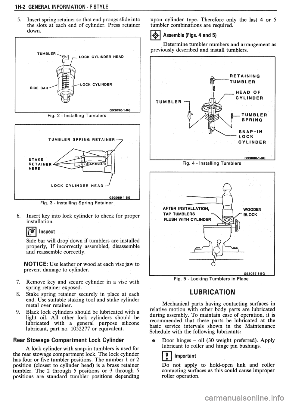
5. Insert spring retainer so that end prongs slide into
upon cylinder type. Therefore only the last 4 or 5
the slots at each end of cylinder. Press retainer
tumbler combinations are required.
down.
TUMBLER \m , LOCK CYLINDER HEAD
SIDE BAR LOCK CYLINDER
Fig.
2 - Installing Tumblers
TUMBLER SPRING RETAINER
LOCK CYLINDER HEAD
Fig.
3 - Installing Spring Retainer
6. Insert key into lock cylinder to check for proper
installation.
Inspect
Side bar will drop down if tumblers are installed
properly, If incorrectly assembled, disassemble
and reassemble correctly.
NOTICE: Use leather or wood at each vise jaw to
prevent damage to cylinder.
7. Remove key and secure cylinder in a vise with
spring retainer exposed.
8. Stake spring retainer securely in place at each
end. Use suitable staking tool and stake cylinder
metal over retainer.
9. Black lock cylinders should be lubricated with a
light oil. All other lock cylinders should be
lubricated with a general purpose silicone
lubricant, part no. 1052277 or equivalent.
Assemble (Figs. 4 and 5)
Determine tumbler numbers and arrangement as
previously described and install tumblers,
TUMBLER
I CYLINDER I
Fig. 4 - Installing Tumblers
AFTER INS WOODEN
TAP TUMBLERS BLOCK
FLUSH
WITH CYLINDER
Fig. 5 - Locking Tumblers in Place
LUBRICATION
Mechanical parts having contacting surfaces in
relative motion with other body parts are lubricated
during assembly. To maintain ease of operation, it is
recommended that these parts be lubricated at the
basic service intervals shown in the Maintenance
Schedule with the following lubricants:
Rear Stowage Compartment Lock Cylinder Door hinges - oil (30 weight preferred). Apply
A lock cylinder with snap-in tumblers is used for lubricant
to roller and hinge pin bushings.
the rear stowage compartment lock. The lock cylinder
Important has four or five tumbler positions. The number 1 or 2
position (closest to cylinder head) is a brass retainer Do
not apply to hold-open link and roller
tumbler. The
2 through 5 positions or 3 through 5 contacting
surfaces as this could cause improper
positions are standard tumbler positions depending roller operation.
Page 1684 of 1825
GENERAL INFORMAVlOM - F STYLE "1-3
Compartment lid hinges - part no. 1052196,
Lubriplate Auto Lube A; part no.
1052349,
Lubriplate Spray Lube A, part no. 8915,
3M
Lithium Spray Lube or equivalent.
Black lock cylinders
- light oil.
e All other lock cylinders - a general purpose
silicone lubricant, part no. 1052277 or equivalent.
e Seat mechanism and door hardware are covered
in the specific body area sections in this manual.
All weatherstrips should be periodically
lubricated with a silicone paste lubricant, part no.
1052363, or equivalent. A thin film of lubricant
should be applied using a clean cloth.
ADHESIVE BODY SlBE MOLDING
The body side moldings are attached to the body
panels with adhesive tape. To insure a good molding
replacement (new or old moldings), the panel surface
should be warm (21°C to 32°C or 70°F to
90°F), clean
and free of any wax or oily film. Two methods are listed
to attach loose molding ends and completely removed
m~ldings.
Molding End Loose
1. Wash affected area with soap and water and wipe
dry. Wipe panel and adhesive side of molding
with a clean rag using oil-free naphtha or alcohol.
If molding has pulled loose from adhesive
backing (tape remains on body panel), do not
remove tape from body. Clean back of molding
and tape on body with oil-free naphtha or alcohol
and proceed with step 3.
2. If needed, apply a length of masking tape as a
molding guide.
A straightedge may also be used
in most cases.
3. Apply adhesive to back of molding and press in
place. If Loctite
414 adhesive (part no. 1052283)
or equivalent is used, apply constant pressure to
molding for 30 seconds or until a firm bond has
been made.
Molding Completely Removed
1.
Wash affected panel area with soap and water
and wipe dry. Remove all traces of adhesive from
body panel and back of molding using oil-free
naphtha or alcohol.
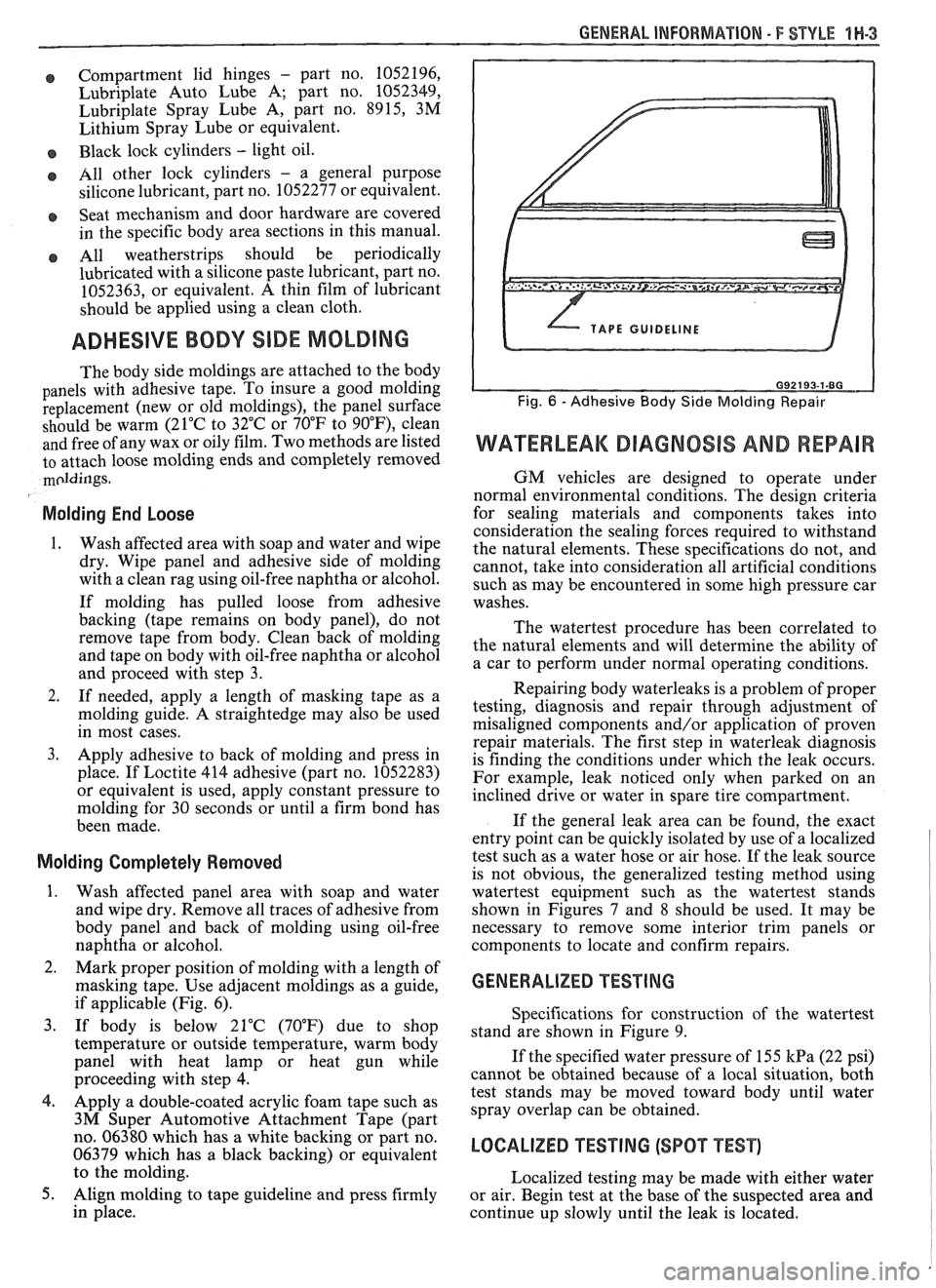
2. Mark proper position of molding with a length of
masking tape. Use adjacent moldings as a guide,
if applicable (Fig. 6).
3. If body is below 21°C (70°F) due to shop
temperature or outside temperature, warm body
panel with heat lamp or heat gun while
proceeding with step
4.
4. Apply a double-coated acrylic foam tape such as
3M Super Automotive Attachment Tape (part
no. 06380 which has a white backing or part no.
06379 which has a black backing) or equivalent
to the molding.
5. Align molding to tape guideline and press firmly
in place.
WATERLEAK DIAGNOSIS AND REPAIR
GM vehicles are designed to operate under
normal environmental conditions. The design criteria
for sealing materials and components takes into
consideration the sealing forces required to withstand
the natural elements. These specifications do not, and
cannot, take into consideration all artificial conditions
such as may be encountered in some high pressure car
washes.
The watertest procedure has been correlated to
the natural elements and will determine the ability of
a car to perform under normal operating conditions.
Repairing body waterleaks is a problem of proper
testing, diagnosis and repair through adjustment of
misaligned components and/or application of proven
repair materials. The first step in waterleak diagnosis
is finding the conditions under which the leak occurs.
For example, leak noticed only when parked on an
inclined drive or water in spare tire compartment.
If the general leak area can be found, the exact
entry point can be quickly isolated by use of a localized
test such as a water hose or air hose. If the leak source
is not obvious, the generalized testing method using
watertest equipment such as the watertest stands
shown in Figures
7 and 8 should be used. It may be
necessary to remove some interior trim panels or
components to locate and confirm repairs.
GENERALIZED TESTING
Specifications for construction of the watertest
stand are shown in Figure 9.
If the specified water pressure of 155
kPa (22 psi)
cannot be obtained because of a local situation, both
test stands may be moved toward body until water
spray overlap can be obtained.
LOCALIZED TEST lNG (SPOT TEST)
Localized testing may be made with either water
or air. Begin test at the base of the suspected area and
continue up slowly until the leak is located.