door lock PONTIAC FIERO 1988 Service User Guide
[x] Cancel search | Manufacturer: PONTIAC, Model Year: 1988, Model line: FIERO, Model: PONTIAC FIERO 1988Pages: 1825, PDF Size: 99.44 MB
Page 1167 of 1825
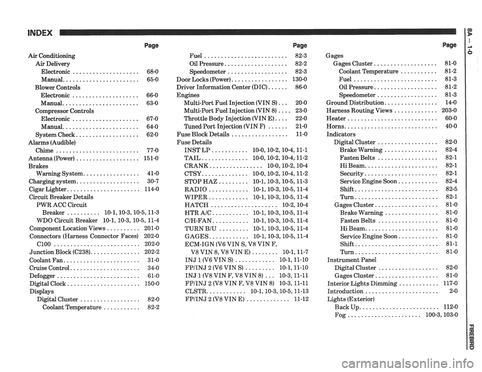
Page
Air Conditioning
Air Delivery
Electronic
.................... 68-0
Manual
....................... 65-0
Blower Controls
Electronic
.................... 66-0
Manual
....................... 63-0
Compressor Controls Electronic
.................... 67-0
Manual
....................... 64-0
................... System Check 62-0
Alarms (Audible)
Chime
......................... 77-0
Antenna(Power) ................... 151-0
Brakes
................. Warning System 41-0
................... Charging system 30-7
...................... Cigar Lighter 114-0
Circuit Breaker Details
PWR ACC Circuit
.......... Breaker 10.1.10.3.10.5.1 1.3
WDO Circuit Breaker
10.1. 10.3. 10.5. 11-4
.......... Component Location Views 201-0
Connectors (Harness Connector Faces) 202-0
el00 .......................... 202-0
............... Junction Block ((2238) 202-2
Coolant Fan
....................... 31-0
Cruise Control
..................... 34-0
Defogger
......................... 61-0
Digital Clock
...................... 150-0
Displays Digital Cluster
.................. 82-0
Coolant Temperature
........... 82-2
Page
......................... Fuel 82-3
................... Oil Pressure 82-2
.................. Speedometer 82-3
................. Door Locks (Power) 130-0
...... Driver Information Center (DIC) 86-0
Engines
... Multi-Port Fuel Injection (VIN S) 20-0
.... Multi-Port Fuel Injection (VIN 8) 23-0
.... Throttle
Body Injection (VIN E) 22-0
...... Tuned
Port Injection (VIN F) 21-0
................. Fuse Block Details 11-0
Fuse Details
........... INST LP 10.0.10.2.10.4.1 1.1
.............. TAIL 10.0.10.2.10.4.1 1.2
................ CRANK 10.0.10.2.1 0.4
.............. CTSY 10~0.10.2.10.4.1 1.2
......... STOP HAZ 10.1.10.3.10.5.1 1.3
............ RADIO 10.1.10.3.10.5.1 1.4
............ WIPER 10.1.10.3.10.5.1 1.4
.................... HATCH 10.2.1 0.4
........... HTR AlC 10.1.10.3.10.5.1 1.4
........... CIH.FAN 10.1.10.3.10.5.1 1.4
......... TURN BIU 10.1.10.3.10.5.1 1.4
............ GAGES 10.1.10.3.10.5.1 1.4
ECM-IGN
(V6 VIN S. V8 VIN F.
........ V8 VIN 8. V8 VIN E) 10.1.1 1.7
............ INJ 1 (V6 VIN S) 10.1.1 1.10
......... FPIINJ 2 (V6 VIN S) 10.1.1 1.10
... INJ 1 (V8 VIN F. V8 VIN 8) 10.3.1 1.11
FPIINJ 2 (V8 VIN F. V8 VIN 8) 10.3.1 1.11
............ CLSTR 10.1.10.3.10.5.1 1.13
............. FPIINJ 2 (V8 VIN E) 11-12
Page
Gages
................... Gages Cluster 81-0
........... Coolant Temperature 81-2
......................... Fuel 81-3
................... Oil Pressure 81-2
.................. Speedometer 81-3
................ Ground Distribution 14-0
Harness Routing Views
............. 203-0
........................... Heater 60-0
............................ Horns 40-0
Indicators
.................. Digital Cluster 82-0
................ Brake Warning 82-4
.................. Fasten Belts 82-1
...................... Hi Beam 82-1
...................... Security 82-1
............ Service Engine Soon 82-4
......................... Shift 82-5
......................... Turn 82-1
................... Gages Cluster 81-0
................ Brake Warning 81-0
.................. Fasten Belts 81-0
...................... Hi Beam 81-0
............ Service Engine Soon 81-0
......................... Shift 81-1
......................... Turn 81-0
Instrument Panel
Digital Cluster
.................. 82-0
Gages Cluster
................... 81-0
............ Interior Lights Dimming 117-0
...................... Introduction 2-0
Lights (Exterior)
........................ Back Up 112-0
...................... Fog 100.3,10 3.0
Page 1175 of 1825
INTRODUCTION
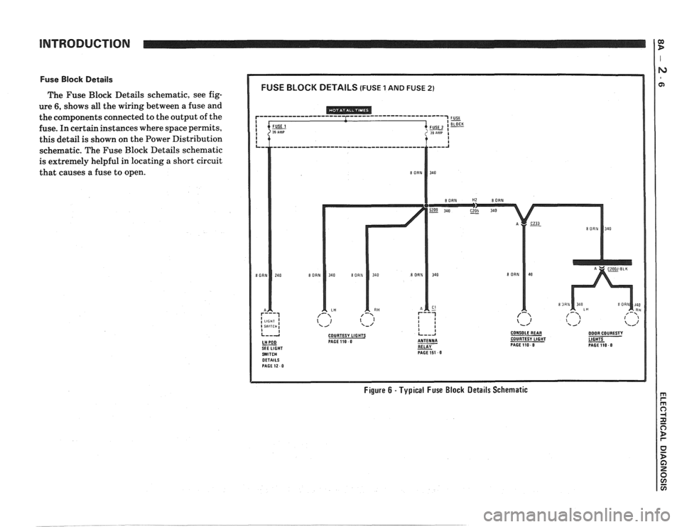
Fuse Block Details
The Fuse Block Details schematic, see fig-
ure
6, shows all the wiring between a fuse and
the components connected to the output of the
fuse. In certain instances where space permits,
this detail is shown on the Power Distribution
schematic. The Fuse Block Details schematic
is extremely helpful in locating
a short circuit
that causes a fuse to open.
COURTESY LIGHTS CONSOLEREAR DOOR COURESTY PAGE110 0 COURTESY LIGHT
RELAY - PAGEllO 0 PAGE151 0
Figure 6 - Typical Fuse Block Details Schematic
Page 1211 of 1825
POWER DISTRIBUTION
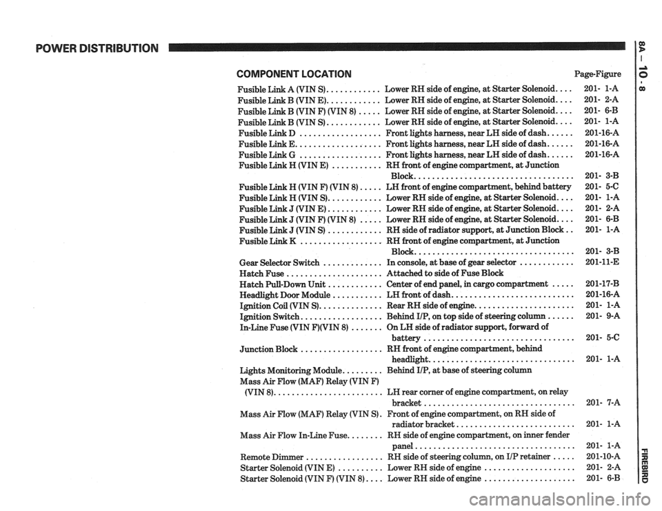
COMPONENT LOCATlON Page-Figure
Fusible Link A (VIN S)
............ Lower RH side of engine. at Starter Solenoid ....
Fusible Link B (VIN E) ............ Lower RH side of engine. at Starter Solenoid ....
Fusible Link B (VIN F) (VIN 8) ..... Lower RH side of engine. at Starter Solenoid ....
............ Fusible Link B (VIN S) Lower
RH side of engine. at Starter Solenoid ....
Fusible Link D .................. Front lights harness. near LH side of dash ......
Fusible Link E ................... Front lights harness. near LH side of dash ......
Fusible Link G .................. Front lights harness. near LH side of dash ......
Fusible Link H (VIN E) ........... RH front of engine compartment. at Junction
Block
...................................
Fusible Link N (VIN F) (VIN 8) ..... LN front of engine compartment. behind battery
Fusible Link H (VIN S)
............ Lower RH side of engine. at Starter Solenoid ....
J (VIN E) ............ Lower RH side of engine, at Starter Solenoid ....
J (VIN F) (VIN 8) ..... Lower RH side of engine, at Starter Solenoid ....
J (VIN S) ............ RH side of radiator support. at Junction Block ..
.................. Fusible Link K RN front of engine compartment. at Junction
Block
...................................
Gear Selector Switch ............. In console, at base of gear selector ............
Hatch Fuse ..................... Attached to side of Fuse Block
Hatch Pull-Down Unit
............ Center of end panel, in cargo compartment .....
Headlight Door Module ........... LH front of dash ...........................
Ignition Coil (VIN S) .............. Rear RH side of engine ......................
Ignition Switch .................. Behind IIP. on top side of steering column ......
In-Line Fuse (VIN F)(VIN 8) ....... On LH side of radiator support. forward of
................................. battery
.................. Junction Block RH front of engine compartment. behind
................................ headlight
Lights Monitoring Module
......... Behind IIP. at base of steering column
Mass Air Flow (MAF) Relay (VIN
F)
........................ (VIN 8) LH rear corner of engine compartment, on relay
................................. bracket
Mass Air Flow (MAF) Relay (VIN S)
. Front of engine compartment. on RH side of
radiator bracket
..........................
Mass Air Flow In-Line Fuse ........ RN side of engine compartment, on inner fender
panel
...................................
Remote Dimmer ................. RH side of steering column. on IIP retainer .....
Starter Solenoid (VIN E) .......... Lower RH side of engine ....................
Starter Solenoid (VIN F) (VIN 8) .... Lower RH side of engine ....................
Page 1215 of 1825
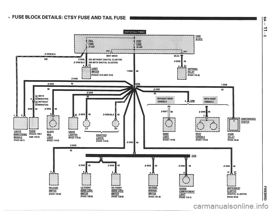
a FUSE BLOCK DETAILS: CTSY FUSE AND TAIL FUSE I:
.8 ORNIBLK
CONVENIENCE
CENTER
LIGHT
- CONSOLE RELAY (PAGE 1140) (PAGE 114-0) (PAGE 40-0)
- SWITCH DOOR LOCK DOOR LOCK MIRROR COMPARTMENT CLUSTER
(PAGE 1340) - S-W a LIGHT - (DIGITAL CLUSTER)
(PAGE 130-0) (PAGE 130-0) (PAGE 141-0) (PAGE 114-1) (PAGE 82-0)
Page 1342 of 1825
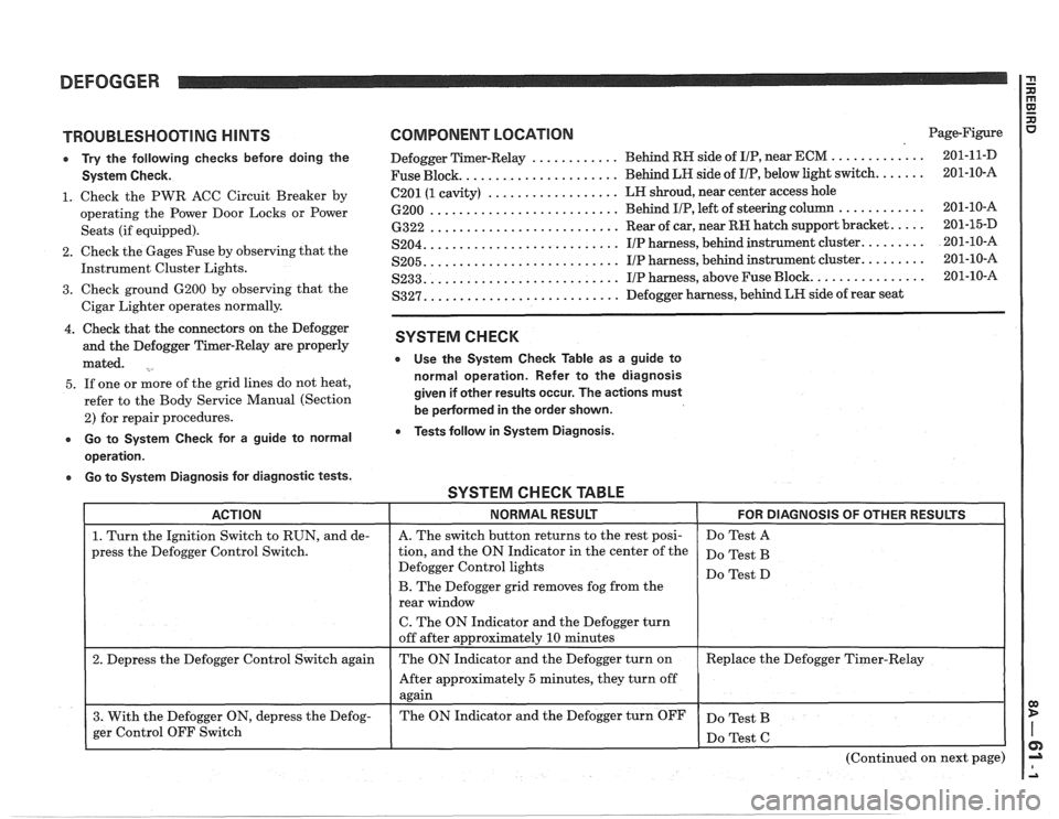
DEFOGGER
TROUBLESHOOTING HINTS
e Try the following checks before doing the
System Check.
1. Check the PWR ACC Circuit Breaker by
operating the Power Door Locks or Power
Seats (if equipped).
2. Check the Gages Fuse by observing that the
Instrument Cluster Lights.
3. Check ground 6200 by observing that the
Cigar Lighter operates normally.
4. Check that the connectors on the Defogger
and the Defogger Timer-Relay are properly
mated.
5. If one or more of the grid lines do not heat,
refer to the Body Service Manual (Section
2) for repair procedures.
e Go to System Check for a guide to normal
operation.
a Go to System Diagnosis for diagnostic tests.
COMPONENT LOCATION Page-Figure
............ ............. Defogger Timer-Relay Behind
RH side of IIP, near ECM 201-1 1-D
..................... Fuse Block. Behind LH side
of I/P, below light switch. ...... 201-10-A
.................. 6201 (1 cavity) LH
shroud, near center access hole
.......................... 6200 Behind IIP, left of steering column ............ 201-10-16
.......................... 6322 Rear of car, near RH hatch support bracket. .... 201-15-D
.......................... S204. IIP harness, behind instrument cluster. ........ 201-10-A
.......................... S205. IIP harness, behind instrument cluster. ........ 201-10-A
.......................... S233. IIP harness, above Fuse Block. ............... 201-10-A
.......................... S327. Defogger harness, behind LR side of rear seat
SYSTEM CHECK
e Use the System Check Table as a guide to
normal operation. Refer to the diagnosis
given if other results occur. The actions must
be
pedormed in the order shown.
Tests follow in System Diagnosis.
SYSTEM CHECK TABLE -- -
ACTION NORMAL RESULT FOR DIAGNOSIS OF OTHER RESULTS
1. Turn the Ignition Switch to RUN, and de-
press the Defogger Control Switch.
2. Depress the Defogger Control Switch again
3. With the Defogger ON, depress the Defog-
ger Control OFF Switch
I
A. The switch button returns to the rest posi-
tion, and the ON Indicator in the center of the
Defogger Control lights
B. The Defogger grid removes fog from the
rear window
C. The ON Indicator and the Defogger turn
off after approximately
10 minutes
The ON Indicator and the Defogger turn on
After approximately
5 minutes, they turn off
again
The ON Indicator and the Defogger turn OFF Do
Test A
Do Test B
Do Test D
Replace the Defogger Timer-Relay
Do Test B
(Continued on next page)
Page 1389 of 1825
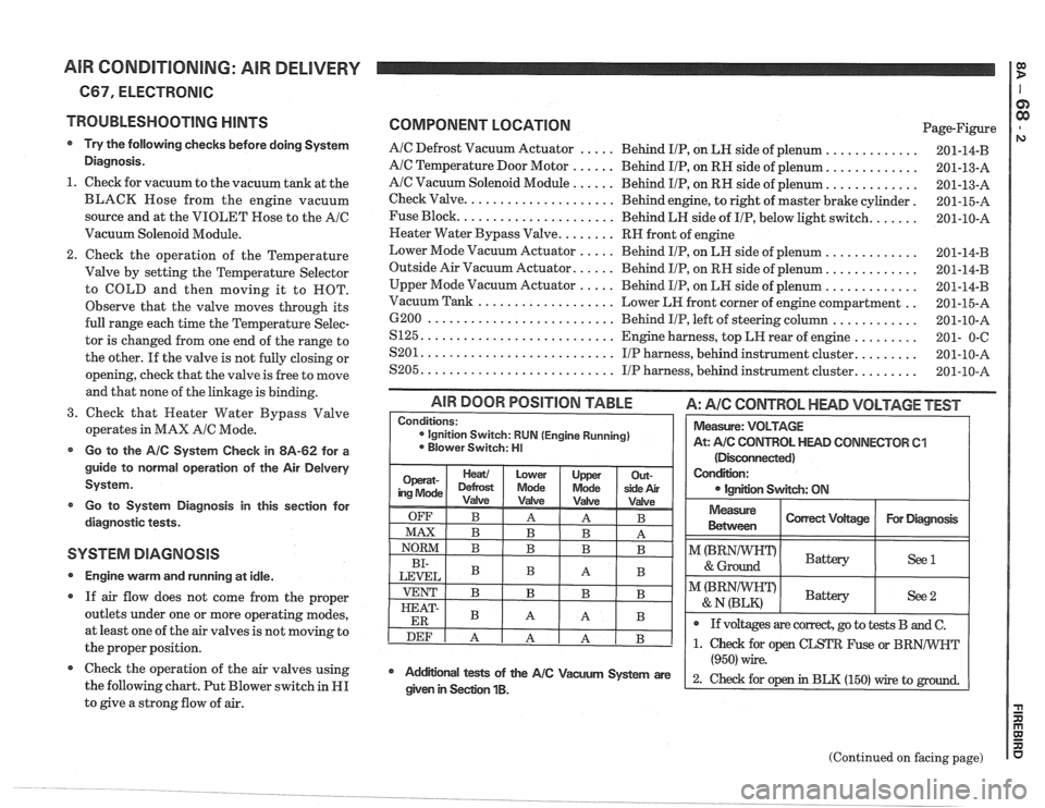
AIR CONDITIONING: AIR DELIVERY I g
667, ELECTRONIC
TROUBLESHOOTING
HINTS
Try the following checks before doing System
Diagnosis.
1. Check for vacuum to the vacuum tank at the
BLACK Hose from the engine vacuum
source and at the VIOLET Rose to the
AIC
Vacuum Solenoid Module.
Check the operation of the Temperature
Valve by setting the Temperature Selector
to COLD and then moving it to ROT.
Observe that the valve moves through its
full range each time the Temperature Selec-
tor is changed from one end of the range to
the other. If the valve is not fully closing or
opening, check that the valve is free to move
and that none of the linkage is binding.
3. Check that Heater Water Bypass Valve
operates in MAX
AIC Mode.
Go to the AIC System Check in 8A-62 for a
guide to normal operation of the Air
Delvery
System.
Go to System Diagnosis
in this section for
diagnostic tests.
SYSTEM DIAGNOSIS
Engine warm and running at idle.
If air flow does not come from the proper
outlets under one or more operating modes,
at least one of the air valves is not moving to
the proper position.
@ Check the operation of the air valves using
the following chart. Put Blower switch in
HI
to give a strong flow of air.
COMPONENT LOCATION Page-Figure
AIC Defrost Vacuum Actuator ..... Behind IIP, on LH side of plenum .............
AIC Temperature Door Motor ...... Behind IIP, on RH side of plenum. ............
AIC Vacuum Solenoid Module ...... Behind IIP, on RH side of plenum. ............
Check Valve. .................... Behind engine, to right of master brake cylinder.
Fuse Block.
..................... Behind LH side of IIP, below light switch. ......
Neater Water Bypass Valve. ....... RH front of engine
Lower Mode Vacuum Actuator
..... Behind IIP, on LH side of plenum .............
Outside Air Vacuum Actuator. ..... Behind IIP, on RH side of plenum. ............
Upper Mode Vacuum Actuator ..... Behind IIP, on LH side of plenum .............
.. Vacuum Tank ................... Lower LH front corner of engine compartment
6200
.......................... Behind IIP, left of steering column ............
S125. .......................... Engine harness, top LH rear of engine .........
........ S201. .......................... IIP harness, behind instrument cluster.
........ S205. .......................... IIP harness, behind instrument cluster.
(Disconnected)
Condition:
IgnEon Swgch: ON
AIR DOOR POSITION TABLE A: AIC CONTROL HEAD VOLTAGE TEST
Measure
Between I Correct Vdtage / For Diagmsk I
Conditions: ignition Switch: RUN (Engine Running)
Blower Switch: HI
I"(BRNIWIFDI & Ground Battery ( See1 I
Measure: VOLTAGE
At:
A/C CONTROL HEAD CONNECTOR 61
I I
@ If voltages are correct, go to tests B and C.
(Continued on facing page)
Mdifional tests of the AIC Vacum System are
(950) wire.
2- ~hd for op in BLK (150) rrire to given in Seclion 1B.
Page 1394 of 1825
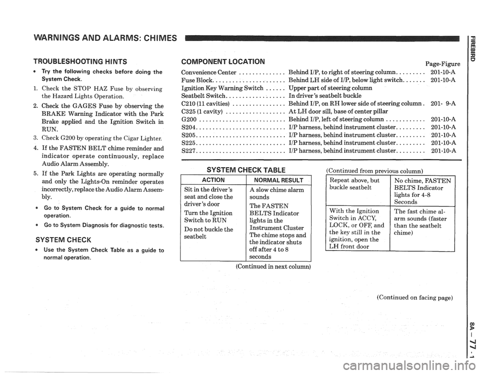
WARNINGS AND ALARMS: CHIMES
TROUBLESHOOTING H lNTS
* Try the following checks before doing the
System Check.
1. Check the STOP HAZ Fuse by observing
the Hazard Lights Operation.
2. Check the GAGES Fuse by observing the
BRAKE Warning Indicator with the Park
Brake applied and the Ignition Switch in
RUN.
3. Check 6200 by operating the Cigar Lighter.
4. If the FASTEN BELT chime reminder and
indicator operate continuously, replace
Audio Alarm Assembly.
5. If the Park Lights are operating normally
and only the Lights-On reminder operates
incorrectly, replace the Audio Alarm Assem-
bly.
Go to System Check for a guide to normal
operation.
Go to System Diagnosis for diagnostic tests.
SYSTEM CHECK
* Use the System Check Table as a guide to
normal operation.
COMPONENT LOCATlON Page-Figure
Convenience Center
.............. Behind IIP, to right of steering column. ........ 201-10-A
Fuse Block.
..................... Behind LH side of IIP, below light switch. ...... 201-10-A
Ignition Key Warning Switch
...... Upper part of steering column
Seatbelt Switch. ................. In driver's seatbelt buckle
C210
(11 cavities) ................ Behind IIP, on RH lower side of steering column. 201-
9-A
6325 (1 cavity) .................. At LH door sill, base of center pillar
6200 .......................... Behind IIP, left of steering column ............ 201-10-A
S204. .......................... IIP harness, behind instrument cluster. ........ 201-10-A
S205. .......................... IIP harness, behind instrument cluster. ........ 201-10-A
S225. .......................... I/P harness, behind instrument cluster. ........ 201-10-A
S227. .......................... IIP harness, behind instrument cluster. ........ 201-10-A
SYSTEM CHECK TABLE
ACTION
Sit in the driver's
seat and close the
driver's door
Turn the Ignition
Switch to RUN
Do not buckle the
seatbelt
NORMAL RESULT
A slow chime alarm
sounds
The FASTEN
BELTS Indicator
lights in the
Instrument Cluster
The chime stops and
the indicator shuts
off after 4 to
8
(Continued from previous column)
buckle
seatbelt
ignition, open the
LH front door
I seconds
(Continued in next column)
(Continued on facing page)
Page 1397 of 1825
WARNINGS AND ALARMS: CHIMES
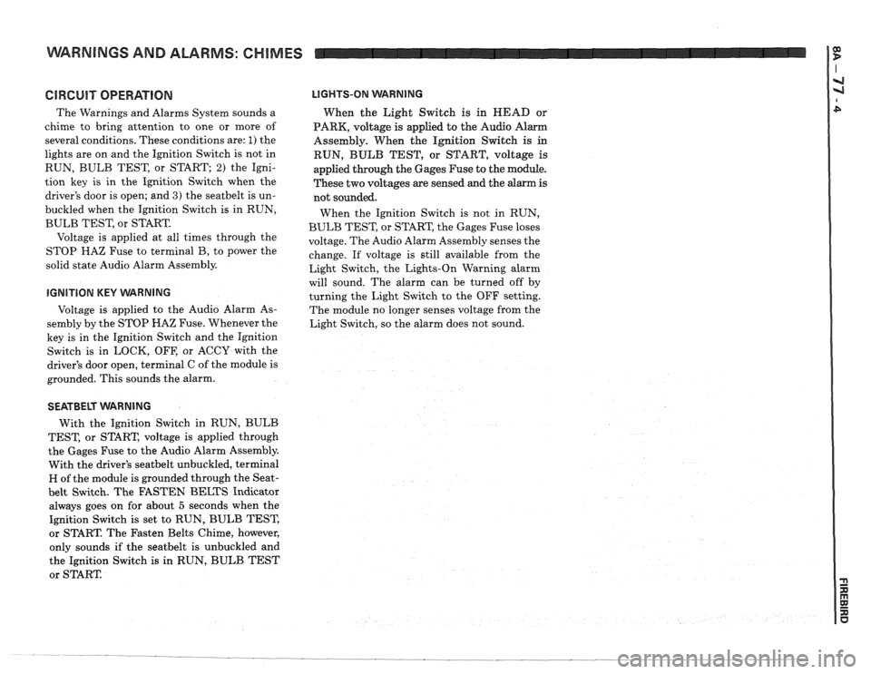
GlRGUlT OPERATION
The Warnings and Alarms System sounds a
chime to bring attention to one or more of
several conditions. These conditions are:
1) the
lights are on and the Ignition Switch is not in
RUN, BULB TEST, or START;
2) the Igni-
tion key is in the Ignition Switch when the
driver's door is open; and
3) the seatbelt is un-
buckled when the Ignition Switch is in RUN,
BULB TEST, or START.
Voltage is applied at all times through the
STOP
HAZ Fuse to terminal B, to power the
solid state Audio Alarm Assembly.
IGNITION KEY VVARNING
Voltage is applied to the Audio Alarm As-
sembly by the STOP HAZ Fuse. Whenever the
key is in the Ignition Switch and the Ignition
Switch is in LOCK, OFF, or ACCY with the
driver's door open, terminal C of the module is
grounded. This sounds the alarm.
LIGHTS-ON WARNING
When the Light Switch is in HEAD or
PARK, voltage
is applied to the Audio Alarm
Assembly. When the Ignition Switch
is in
RUN, BULB TEST, or START, voltage is
applied through the Gages Fuse to the module.
These two voltages are sensed and the alarm is
not sounded.
When the Ignition Switch is not in RUN,
BULB TEST, or START, the Gages Fuse loses
voltage. The Audio Alarm Assembly senses the
change. If voltage is still available from the
Light Switch, the Lights-On Warning alarm
will sound. The alarm can be turned off by
turning the Light Switch to the OFF setting.
The module no longer senses voltage from the
Light Switch, so the alarm does not sound.
SEATBELT WARNING
With the Ignition Switch in RUN, BULB
TEST, or START, voltage is applied through
the Gages Fuse to the Audio Alarm Assembly.
With the driver's
seatbelt unbuckled, terminal
H of the module is grounded through the Seat-
belt Switch. The FASTEN BELTS Indicator
always goes on for about
5 seconds when the
Ignition Switch is set to RUN, BULB TEST,
or START. The Fasten Belts Chime, however,
only sounds if the
seatbelt is unbuckled and
the Ignition Switch
is in RUN, BULB TEST
or START
Page 1433 of 1825
DRIVER INFORMATION CENTER (DDC) I $
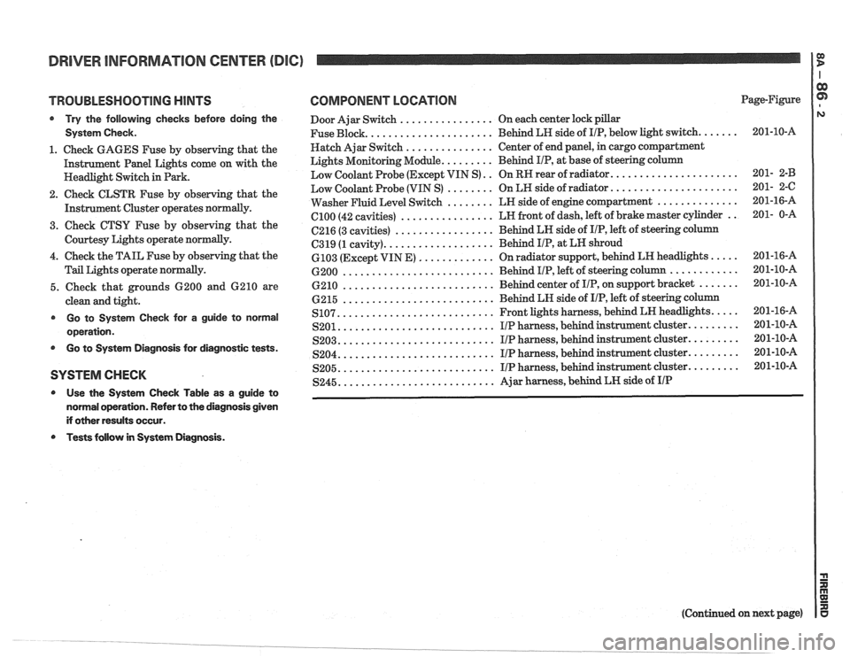
TROUBLESHOOTING HINTS
@ Try the following checks before doing the
System Check.
1. Check GAGES Fuse by observing that the
Instrument Panel Lights come on with the
Headlight Switch in Park.
2. Check CLSTR Fuse by observing that the
Instrument Cluster operates
normally.
3. Cheek CTSU Fuse by observing that the
Courtesy Lights operate normally.
4. Check the TAIL Fuse by observing that the
Tail Lights operate normally.
5. Check that grounds 6200 and 6210 are
clean and tight.
@ Go to System Check for a guide to norrnal
operation.
@ Go to System Diagnosis for diagnostic tests.
SYSTEM CHECK
@ Use the System Check Table as a guide to
normal operation. Refer to the diagnosis given
if other results occur.
Tests follow in System Diagnosis.
COMPONENT LOCATION Page-Figure
Door Ajar Switch
................ On each center lock pillar
..................... Fuse Block.
Behind LH side of IIP, below light switch. ...... 201-10-A
Hatch Ajar Switch
............... Center of end panel, in cargo compartment
Lights Monitoring Module.
........ Behind IIP, at base of steering column
..................... Low Coolant Probe (Except VIN S) .. On RR rear of radiator. 201- 2-B
..................... Low Coolant Probe (VIN S) ........ On LR side of radiator. 201- 2-C
.............. Washer Fluid Level Switch ........ LN side of engine compartment 201-16-A
................ el00 (42
cavities) LN
front of dash, left of brake master cylinder .. 201- 0-A
................. 6216 (3 cavities) Behind LN side
of IIP, left of steering column
.................. C319 (1 cavity). Behind I/P, at
LN shroud
............. 6103 (Except VIN E) On radiator support, behind LH headlights. .... 201-16-A
.......................... ............ 6200 Behind IIP, left of steering column 201-10-A
.......................... 6210 Behind center of IIP, on support bracket ....... 201-10-A
.......................... 6215 Behind
LH side of IIP, left of steering column
.......................... .... S107. Front lights harness, behind LN headlights. 201-16-A
.......................... S201. IIP harness, behind instrument cluster. ........ 201-10-A
.......................... S203. I/P harness, behind instrument cluster. ........ 201-10-A
.......................... S204. I/P harness, behind instrument cluster. ........ 201-10-A
.......................... S205. I/P harness, behind instrument cluster. ........ 201-10-A
.......................... S245. Ajar harness, behind LN side of IIP
(Continued on next page)
Page 1458 of 1825
HEADLIGHT DOORS
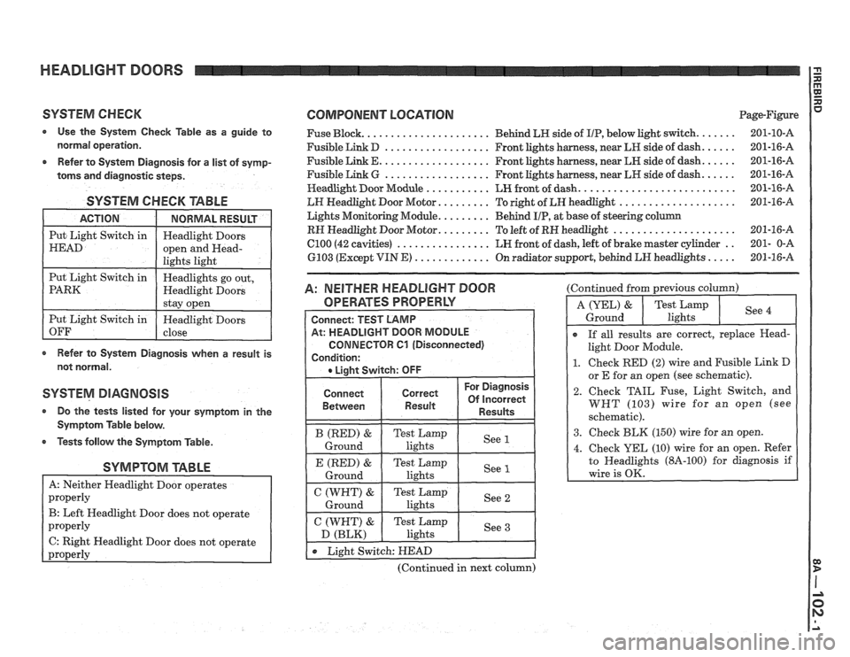
SYSTEM CHECK COMPONENT LOCATION Page-Figure
Use the System Check Table as a guide to Fuse Block. ..................... Behind LN side of IIP, below light switch. ...... 201-10-A
normal operation. Fusible Link D .................. Front lights harness, near LR side of dash. ..... 201-16-A
..... .................. Refer to System Diagnosis for a list of symp- Fusible Link E. Front lights harness, near LN side of dash. 201-16-A
..... .................. toms and
diagnostic steps. Fusible Link G Front lights harness, near LH side of dash. 201-16-A
.......................... Headlight
Door Module ........... LH front of dash. 201-16-A
SYSTEM CHECK TABLE
Refer to System Diagnosis when a result is
not normal.
SYSTEM DIAGNOSIS
a Do the tests listed for your symptom in the
Symptom Table below.
Tests follow the Symptom Table.
SYMPTOM TABLE
B: Left Headlight Door does not operate
C: Right Headlight Door does not operate
-
LH Headlight Door Motor. ........ To right of LH headlight .................... 201-16-A
Lights Monitoring Module.
........ Behind UP, at base of steering column
RH Headlight Door Motor. ........ To left of RN headlight ..................... 201-16-A
C100 (42 cavities) ................ LH front of dash, left of brake master cylinder .. 201- 0-A
6103 (Except VIN
E) ............. On radiator support, behind LN headlights ..... 201-16-A
A: NEITHER HEADLIGHT DOOR
OPERATES PROPERLY
Connect
Between
(Continued in next column) (Continued
from previous column)
I
r If all results are correct, replace Head-
light Door Module.
1. Check RED (2) wire and Fusible Link D
or E for an owen (see schematic).
2. Check TAIL Fuse, Light Switch, and
WHT (103) wire for an open (see
schematic).
3. Check BLK (150) wire for an open.