fog light PONTIAC FIERO 1988 Service Owner's Manual
[x] Cancel search | Manufacturer: PONTIAC, Model Year: 1988, Model line: FIERO, Model: PONTIAC FIERO 1988Pages: 1825, PDF Size: 99.44 MB
Page 1600 of 1825
LIGHTING SYSTEMS AND HORNS 8B-I
SECTION 8B
NG SYSTEMS AND HORNS
CONTENTS
........................... GENERAL DESCRIPTION 8B-1
Exterior Lights
....................... ................... Back-up Lights .. 8B- 1
Center High-Mounted Stoplight .................... 8B-1
Exterior Light Monitor .................................. 8B-1
............................ .................... Fog Lights .. 8B-1
Front Parking/Turn Signal Lights ................ 8B-2
............................... Hazard Flashers .. ........ 8B-2 .................................................... Headlights 8B-2
License Plate Lights ..................................... 8B-2
Light Switch ............................................... 8B-2
............... Rear Tail/Stop/Turn Signal Lights 8B-2
Sidemarker Lights ........................................ 8B-2
Turn Signals .......................................... 8B-2
......................... Underhood Light ... ........ 8B-2
Horns .......................................................... 8B-3
....................................... ON-CAR SERVICE 8B-3
Exterior Lights
............................................. Back-up Lights 8B-3
Center High-Mounted Stoplight .................... 8B-3
Fog Lights .................................................... 8B-4
Front Parking/Turn Signal Lights ................ 8B-4
Hazard Flasher .............................................. 8B-5
....................................................... Headlights 8B-5
License Plate Lights ..................................... 8B-7
............... Rear Tail/Stop/Turn Signal Lights 8B-8
.......................................... Sidemarker Lights 8B-8
................... ............... Turn Signal Flasher .. 8B-9
......................................... Underhood Light 8B-9
Horns ................................................................. 8B-9
REPLACEMENT BULB
.................................... SPECIFICATIONS 8B- 10
The following information, previously shown in this section,
has been moved to the sections shown.
Back-up Lights Switch
............................. ... ............................................................................ 7
................................................................................................................................. Fuse Block 8A
Ignition Switch ........................................................................................................................... 3B
Interior Lights
................................................................................................................... 8A, 8C
Neutral Start Switch ..................................................................................................................... 7
Parking Brake Warning Switch
......................... ... .................................................................... 5
........................................................................ Seat Belt, Key and Headlight Warning Alarm 8A
Stoplight Switch .......................... .. ............................................................................................... 5
Windshield
Wipers/Washers .................................................................................................... 8E
GENERAL DESCRIPTION
The exterior lighting system includes the
headlights (and headlight motors to raise or lower the
headlights), front
parkinghurn signal lights, front
cornering lights, fog lights, rear
tail/stop/turn signal
lights, back-up lights, license plate lights, center
high-mounted stoplight, and the underhood light; it
also includes all associated wiring, controls and related
hardware for these lights.
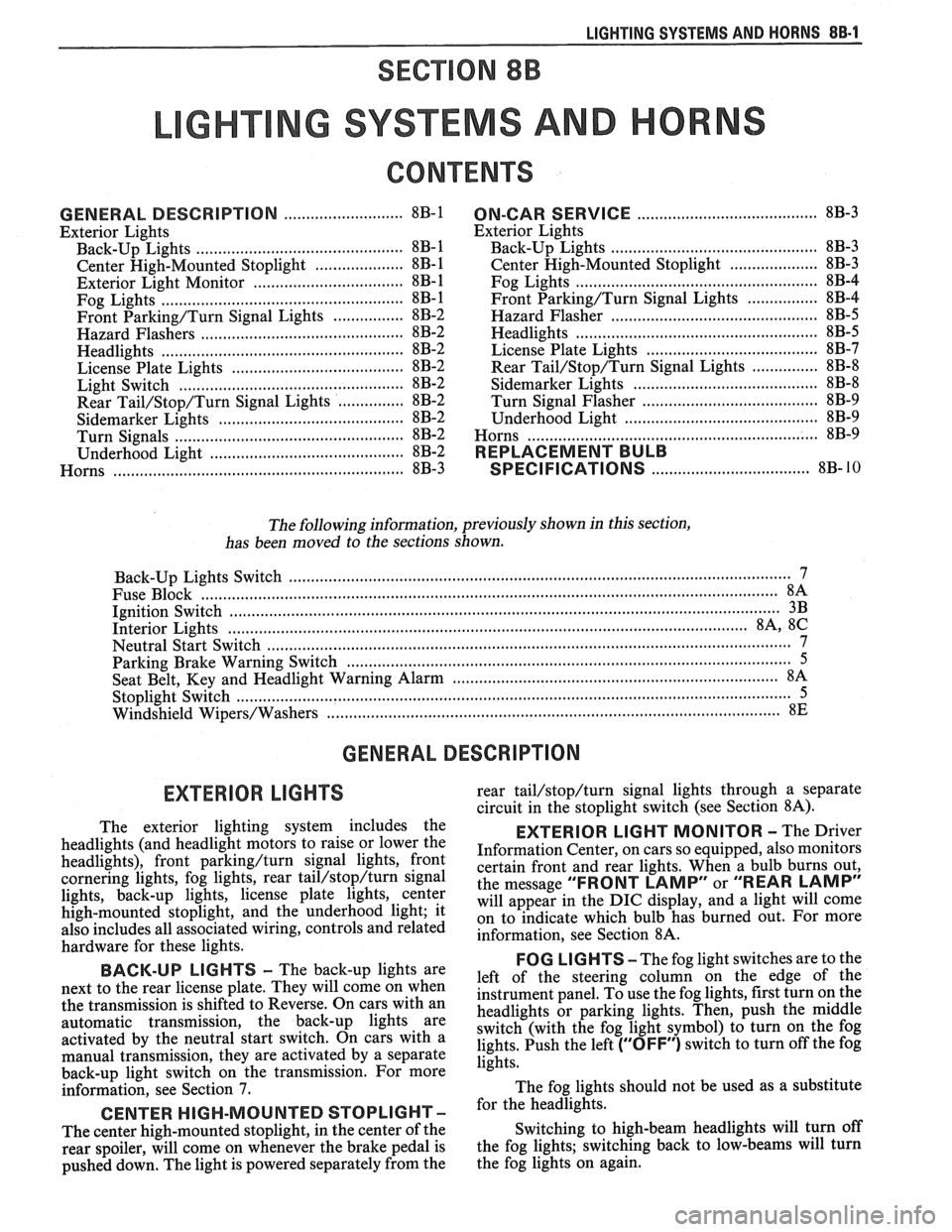
BACK-UP LIGHTS - The back-up lights are
next to the rear license plate. They will come on when
the transmission is shifted to Reverse. On cars with an
automatic transmission, the back-up lights are
activated by the neutral start switch. On cars with a
manual transmission, they are activated by a separate
back-up light switch on the transmission. For more
information, see Section 7.
CENTER HIGH-MOUNTED STOPLIGHT-
The center high-mounted stoplight, in the center of the
rear spoiler, will come on whenever the brake pedal is
pushed down. The light is powered separately from the rear
tail/stop/turn signal
lights through a separate
circuit in the stoplight switch (see Section
8A).
EXTERIOR LIGHT MONITOR - The Driver
Information Center, on cars so equipped, also monitors
certain front and rear lights. When a bulb burns out,
the message
"FRONT LAMP" or "REAR LAMP"
will appear in the DIC display, and a light will come
on to indicate which bulb has burned out. For more
information, see Section
8A.
FOG LIGHTS -The fog light switches are to the
left of the steering column on the edge of the
instrument panel. To use the fog lights, first turn on the
headlights or parking lights. Then, push the middle
switch (with the fog light symbol) to turn on the fog
lights. Push the left
("OFF") switch to turn off the fog
lights.
The fog lights should not be used as a substitute
for the headlights.
Switching to high-beam headlights will turn off
the fog lights; switching back to low-beams will turn
the fog lights on again.
Page 1601 of 1825
88-2 LIGHTING SYSTEMS AND HORNS
The fog lights must be aimed for proper
illumination of the road. Fog light
aim should be
checked: at least once a year; when a new light housing
is installed; or if service or repairs in the front end area
have (or may have) disturbed the fog light mountings.
FRONT PARKING/TURM SIGNAL
LIGHTS - Pushing either side of the instrument panel
switch will turn on the front parking lights. (Pushing
the left side of the switch will also turn on the
headlights.) When the ignition is on and the turn signal
lever is moved, the appropriate front parking light
flashes to signal a turn. Both lights will flash when the
hazard flashers are on.
If the driver's door is opened when the parking
lights are on, a warning tone will sound. For more
information, see Section
8A-77.
HAZARD FLASHERS - The hazard warning
flasher is part of the turn signal circuit. Pushing in the
button (on the right side of the steering column) will
cause the front and rear turn signal lights, and the front
sidemarker lights, to flash. Pull out the collar around
the button to turn off the hazard flashers.
The hazard flashers will work with the ignition
either off or on. When the hazard flashers are on, the
turn signals do not
work.
The hazard flashers will stop flashing and stay on
brightly if the brake pedal is pushed down.
HEADLIGHTS - The headlights are controlled
by the switch on the instrument panel (to the left of the
speedometer). They will come on whether or not the
ignition is turned on. Pushing the upper left side of the
switch turns on the headlights and causes the headlight
motors to raise the headlights. Pushing the bottom part
of the switch turns off the headlights, and they should
lower.
If the driver's door is opened when the ignition
is off and the headlights are on, a warning tone will
sound. For more information, see Section
8A-77.
Headlight low-beam and high-beam are
controlled by the turn
signal/multifunction lever on
the left side of the steering column. When the
headlights are on, pull the lever toward the steering
wheel until the switch clicks; the lights will change
from low-beam to high-beam, or from high-beam to
low-beam. An indicator light on the center instrument
cluster will come on when the high-beam headlights
are on.
The headlights must be aimed for proper
illumination of the road. Headlight aim should be
checked: at least once a year; when a new headlight
bulb is installed; or if service or repairs in the front end
area have (or may have) disturbed the headlights or
their mountings. The headlight bezels do not need to
be removed to aim the headlights.
Headlight focus is set when the sealed-beam unit
is made; no adjustment for focus is necessary or
possible.
Some state and local laws specify
requirements for headlight aim; these laws
must be followed.
LICENSE PLATE LBGHTS -A light above the
rear license plate will come on when the headlights or
parking lights are on.
LIGHT SWITCH - Most exterior lights are
controlled by the switch on the instrument panel, to the
left of the speedometer. Pushing the upper right part
of the switch turns on the front parking lights, the
taillights and the sidemarker lights. (It also turns on
the instrument panel lights.) Pushing the upper left
part of the switch turns on all these lights plus the
headlights. Pushing the bottom part of the switch turns
off all lights.
In some cases (such as going through a car wash),
it may be desirable to raise the headlights without
leaving the headlights on. To do so, push the upper
right part of the switch to turn on the parking lights.
Then, lightly push the upper right part of the switch;
the headlights will raise but will not turn on.
(Remember that the parking lights and taillights will
stay on.)
For more information on this switch (including
on-car service), see Section
8C. Also see Section 8C for
information on interior lights.
REAR TAlL/STOP/TURN SIGNAL
LIGHTS - The rear tail/stop/turn signal lights are
part of the same light assembly. Pushing either side of
the instrument panel switch turns on the taillights.
When the brake pedal is pushed down, the lights glow
brighter to serve as stoplights.
Moving the turn signal lever when the ignition is
on causes the appropriate rear lights to flash. (If the
brake pedal is held down and a turn is signalled, one
side will flash and the other will stay on brightly.)
All lights will flash when the hazard flashers are
on. However, if the brake pedal is pushed while the
hazard flashers are on, the lights will stop flashing and
stay on brightly.
SIDEMARKER LIGHTS -The front and rear
sidemarker lights will come on when the headlights or
parking lights are on. Both front and rear sidemarker
lights also have reflectors; they will shine when struck
by light, whether or not the car's lights are on.
If the headlights or parking lights are off when a
turn is signalled, the front sidemarker light will flash
in unison with the front turn signal light on the same
side. If the lights are on when a turn is signalled, the
front
sidemarker light and front turn signal light flash
alternately.
TURN SlG N ALS - The front turn signals are
combined with the front parking lights. The rear turn
signals are part of the rear
tail/stop/turn signal lights.
The turn signals work only when the ignition is on, and
the hazard flashers are turned off.
The turn signals are controlled by the turn
signal/multifunction lever on the left side of the
steering column. Moving the lever all the way up or
down (past the detent) will turn on the turn signals.
When the turn is completed, the lever will return to
neutral and the turn signals will stop flashing.
For changing lanes or shallow turns where the
steering wheel does not move far enough to cancel the
signal, move the turn signal lever only to the first
detent. When the lever is released, it will return to
neutral and the turn signals will cancel.
UNDERHOOD LIGHT - The underhood light
will come on when the hood is raised.
Page 1602 of 1825
LIGHTING SYSTEMS AND HORNS 8B-3
HORNS the steering wheel sounds the horn by closing the horn
relay (in the convenience center behind the instrument
panel, to the right of the steering column). The horns
The holm(§) are mounted behind the front fascia use a solenoid-operated diaphragm to generate sound.
on the driver's side. $ushing the pad in the center of See Section 8A-40 for wiring and circuit information.
ON-CAR SERVICE
Wiring diagrams and other diagnosis information
is given in Section
8A. Information on properly
repairing wiring harnesses, connectors, etc., is on
8A-5.
Most lighting problems are caused by loose
connectors, open or shorted wiring, burned-out bulbs,
bad switches, inadequate ground or blown fuses. Many
of these require only replacement of a defective part.
When replacing a part that requires a special procedure
(such as a lens and housing assembly sealed together),
follow the instructions normally included in the
replacement parts package.
When removing a part that requires special
sealing items (such as sealing washers), be sure to
reinstall those items when replacing the part. Also, if
any body sealing items (grommets, etc.) are disturbed,
be sure to repair them so the passenger compartment
remains properly sealed.
EXTERlOR LIGHTS
BACK-UP LIGHTS
Fig. 8B-8
Replacement Bulb: Trade No. 1156, 32
Candlepower
To replace a back-up light bulb, see "Rear
Tail/Stop/Turn Signal Lights9' in this section. For
information on the back-up light switch on the
transmission, see Section
7.
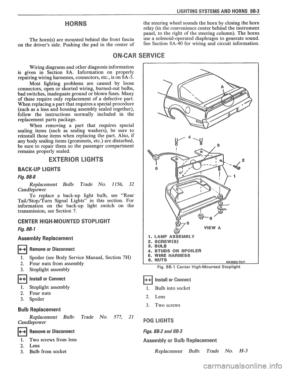
CENTER HIGH-MOUNTED STOPLIGHT
Fig. 8B-7
Assembly Replacement
Remove or Disconnect
1. Spoiler (see Body Service Manual, Section 7H)
2. Four nuts from assembly
3. Stoplight assembly
Install or Connect
1. Stoplight assembly
2. Four nuts
3. Spoiler
Bulb Replacement
Replacement Bulb: Trade No. 577, 21
Candlepo wer
Remove or Disconnect
1. Two screws from lens
2. Lens
3. Bulb from socket
1. LAMP ASSEMBLY
2. SCREW($) 3. BULB
4. STUD8 ON SPOILER 5. WIRE HARNESS
Fig. 8B-1 Center High-Mounted Stoplight
Install or Corrnect
1. Bulb into socket
2. Lens
3. Two screws
FOG LIGHTS
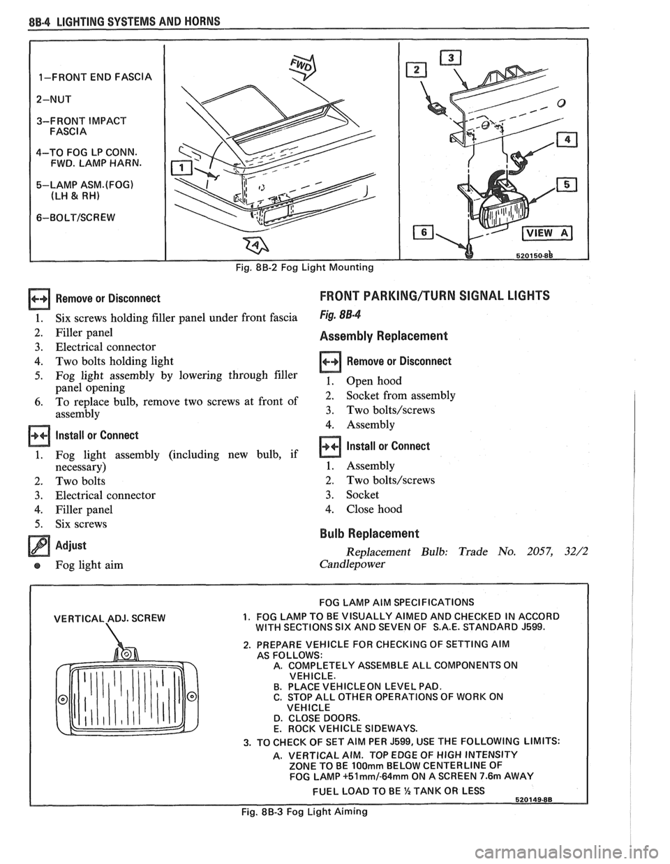
Figs. 8B-2 and 88-3
Assembly or Bulb Replacement
Replacement Bulb: Trade No. H-3
Page 1603 of 1825
8B-4 LIGHTING SYSTEMS AND HORNS
Remove or Disconnect
Six screws holding filler panel under front fascia
Filler panel
Electrical connector
Two bolts holding light
Fog light assembly by lowering through filler
panel opening
To replace bulb, remove two screws at front of
assembly
Install or Connect
Fog light assembly (including new bulb, if
necessary)
Two bolts
Electrical connector
Filler panel Six screws
Adjust
Fog light aim
FRONT PARKING/TURN SIGNAL LIGHTS
Fig. 88-4
Assembly Replacement
Remove or Disconnect
1. Open hood
2. Socket from assembly
3. Two bolts/screws
4. Assembly
Install or Connect
1. Assembly
2. Two bolts/screws
3. Socket
4. Close hood
Bulb Replacement
Replacement Bulb: Trade No. 2057, 32/2
Candlepower
VERTICAL ADJ. SCREW
FOG LAMP AIM SPECIFICATIONS
1. FOG LAMP TO BE VISUALLY AIMED AND CHECKED IN ACCORD WITH SECTIONS SIX AND SEVEN OF S.A.E. STANDARD J599.
2. PREPARE VEHICLE FOR CHECKING OF SETTING AIM
AS FOLLOWS:
A. COMPLETELY ASSEMBLE ALL COMPONENTS ON
VEHICLE.
B. PLACE
VEHICLEON LEVEL PAD.
C. STOP ALL OTHER OPERATIONS OF WORK ON
VEHICLE
D. CLOSE DOORS.
E. ROCK VEHICLE SIDEWAYS.
3. TO CHECK OF SET AIM PER J599, USE THE FOLLOWING LIMITS:
A. VERTICAL AIM. TOP EDGE OF
HIGH INTENSITY
ZONE TO BE 100mm BELOW CENTERLINE OF
FOG LAMP +51mm/-64mm ON A SCREEN 7.6m AWAY
FUEL LOAD TO BE %TANK OR LESS
Fig. 88-3 Fog Light Aiming
Page 1609 of 1825
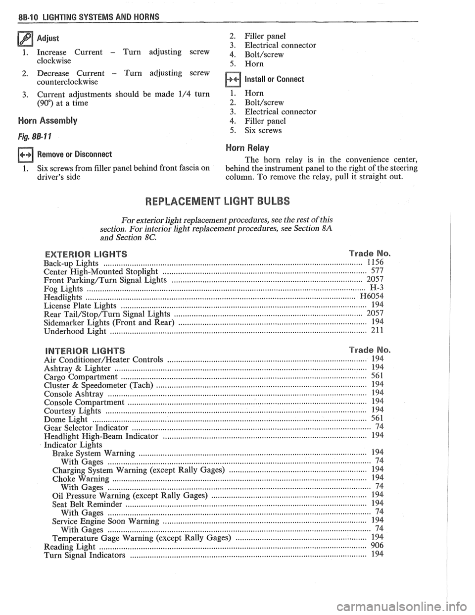
Adjust 2 . Filler panel 3 . Electrical connector
1 . Increase Current - Turn adjusting screw 4 . ~~l~/~~~~~
clockwise 5 . Horn
2 . Decrease Current . Turn adjusting screw
counterclockwise
Install or Connect
3 . Current adjustments should be made 1/4 turn
(90") at a time
Horn Assembly
Remove or Disconnect
1 . Six screws from filler panel behind front fascia on
driver's side 1
. Horn
2 . Bolt/screw
3 . Electrical connector
4
. Filler panel
5 . Six screws
Horn Relay
The horn relay is in the convenience center.
behind the instrument panel to the right of the steering
column
. To remove the relay. pull it straight out .
REPLACEMENT LIGHT BULBS
For exterior light replacement procedures. see the rest of this
section
. For interior light replacement procedures. see Section $A
and Section 8C .
EXTERIOR LIGHTS Trade No . ...................................................................................................................... Back-up Lights 1 156
Center
High-Mounted Stoplight ............................................................................................. 577
Front Barking/Turn Signal Eights ..................................................................................... 2057
Fog Lights
............................................................................................................................... H-3
Headlights ....................................................................................................................... H6054 ................................................................................................................ License Plate Lights 194
.................................................................................... Rear Tail/Stop/Turn Signal Lights 2057
Sidemarker Lights (Front and Rear) ...................................................................................... 194 ..................................................................................................................... Underhood Light 211
BNTERBOR LIGHTS Trade No .
......................................................................................... Air Conditioner/Heater Controls 194 .................................................................................................................. Ashtray & Lighter 194 .............................................................................................................. Cargo Compartment 561
................................................................................................ Cluster & Speedometer (Tach) 194 ..................................................................................................................... Console Ashtray 194 ............................................................................................................. Console Compartment 194
Courtesy Lights
..................................................................................................................... 194 ......................................................................................................................... Dome Light 561
Gear Selector Indicator
............................................................................................................ 74 .......................................................................................... Headlight High-Beam Indicator 194
Indicator Lights
..................................................................................................... Brake System Warning 194
With Gages
........................................................................................................................ 74
............................................................... Charging System Warning (except Rally Gages) 194 .................................................................................................................... Choke Warning
194
With Gages
........................................................................................................................ 74
...................................................................... Oil Pressure Warning (except Rally Gages) 194 ............................................................................................................ Seat Belt
Reminder 194
With Gages
.................................... ... ................................................................................. 74 ............................................................................................. Service Engine Soon Warning 194
With Gages
..................................................................................................................... 74 ............................................................ Temperature Gage Warning (except Rally Gages) 194
........................................................................................................................ Reading
Light 906 ............................................................................................................ Turn Signal Indicators 194
Page 1612 of 1825
INSTRUMENT PANEL, GAGES & CONSOLE 8C-'I
SECTION 8C
NSTRUMENT PANEL, GAGES & CONSOLE
CONTENTS
General Description ................................... 8C-1
Instrument Panel and Gages ........................ 8C-1
Printed Circuit .......................................... 8C-1
Instruments ................................................... 8C- 1
Speed Sensors
............................ .. ............. 8C- 1
Pinion Gear
............................................. 8C-2
Photo Speed Sensor ................................ 8C-2
PM Generator ................... .. ...... ............... 8C-2
Speedometer ................................................ 8C-2
Mechanical ....................... .. .................... 8C-2
Quartz ........................ .. .......................... 8C-2
Digital .................... .. ...... ................. 8C-2
Fuel Gage .................................................... 8C-2
Temperature Warning Light ...................... 8C-3
Generator Warning Light ............................ 8C-3
Engine Oil Pressure Light ............................ 8C-3
"Service Engine Soon" Light ....................... 8C-3
Upshift Indicator Light .............................. 8C-3
Diagnosis .................... .. ........................... 8C-3
General Information .................................. 8C-3
Instrument Panel & Gages ...................... ..... 8C-3
On-Car Service ......................... .. ........... 8C-4
Instrument Panel Pad ................................... 8C-4
Instrument Panel Cluster ........................... 8C-4
Instrument Panel Carrier ............................. 8C-4
Headlight Switch .......................................... 8C-4
Console Mounted Switches and
Accessories
............................................... 8C-4
Console ......................................................... 8C-4
Speedometer .................................................. 8C-5
Illustra3ions ................................................. 8C-5
IP Pad ........................................................... 8C-5
IP Carrier ................................................... 8C-6
Instrument Cluster ....................................... 8C-6
Lower IP Covers ......................................... 8C-7
IP Trimplates ............................................... 8C-7
IP Hush Panels; with A/C .......................... 8C-8
..................... IP Lower Trim Pad (Console) 8C-8
Map Holder or Map Pocket ........................ 8C-8
IP Hush Panels; without A/C ..................... 8C-9
Radio Mounting ........................................... 8C-9
Subwoofer & Hatch Release
Switches/Covers ........................................ 8C- 10
Foglamp Switch/Cover ................................ 8C- 10
Oil Pressure and Temperature
Switches
..................................................... 8C-11
Heater/Ventilation/Defroster
Ductwork .................................................. 8C- 12
A/C and Defroster Ductwork ..................... 8C-13
Ram Vent System Ductwork ....................... 8C-14
Console Mounted Switches
&
Accessories ................................................. 8C- 14
Dash Insulators
............................................ 8C- 15
Heater Floor Outlet
..................................... 8C-15
................ Headlamp/Parking Lamp Switch 8C- 15
............. Dash Mounted Accessory Switches 8C- 15
GENERAL DESCRIPTION
INSTRUMENT PANEL AND GAGES
INSTRUMENTS
Instruments consist of fuel gage, temperature
The instrument panel on most cars is a sing,e unit indicator light, generator light, oil pressure indicator
design and all parts attach to the main instrument light, and speedometer. See Section 9F for optional
panel with clips and screws. To service the instrument Gages and tachometer. Service on instruments
panel and components see on-car service information, can be obtained through authorized repair stations.
However, knowledge of instrument circuit checks will
PRINTED CIRCUIT
All models are equipped with printed circuits
which supply current to most instrument panel lights
and instruments. These circuits are made of copper foil
which is die cut and bonded to a polyester base film
(usually mylar). The printed circuit electrical power is
supplied by a connector containing several wires, as
shown in the instrument panel wiring harness
installation instructions. The connector also helps
retain the printed circuit to the speedo cluster. The rest
of the circuit is retained by additional connectors (if
used) and snap-in
bulbs/sockets. For individual
printed circuit diagrams, see Section
8A-80/8 1/82/83,
'Instrument Panel'. help
in determining if operating difficulties lie in the
instrument itself or its related circuit.
Instruments have been designed for easy removal
by elimination of separate wiring. With the wiring
provisions integrated with the instrument panel wiring,
the instruments can be removed after removing the
trim and lens.
SPEED SENSORS
There are three speed sensors currently in use:
1. PINION GEAR; used in mechanical systems
2. PHOTO SPEED SENSORS; used in mechanical
systems
3. PM GENERATOR; used in electronic systems
Page 1674 of 1825
MISCELLANEOUS ACCESSORIES 96-4
SCELLANEOUS ACCESSOR
General Description ................................. 9G-1
Rally Gages .................................................. 9G- 1
Tachometer ................................................. 9G- 1
Trip Odometer
............................................. 9G- 1
Electric Rear Window Defogger ................. 9G-2
Power Remote Control Rearview
Mirror ........................................................ 9G-2
Diagnosis .................................................... 9G-2
Rally Gages ............................................... 9G-2
Tachometer .................................... .... .... 9G-2
Electric Rear Window Defogger ................. 9G-2
Power Remote Control Rearview
Mirror ........................................................ 96-2
Dash and Console Mounted
Accessory Switches
................................. 9G-4
General Description .................................. 9G-4
Electronic Glare Control Mirror ................. 9G-4
On-Car Service ............................................. 9G-4
Rally Gages, Tach ....................................... 96-4.
Rear Window Defogger ............................ 96-4.
Power Remote Control Mirror .................... 9G-4
GENERAL BESCRIP"T0N
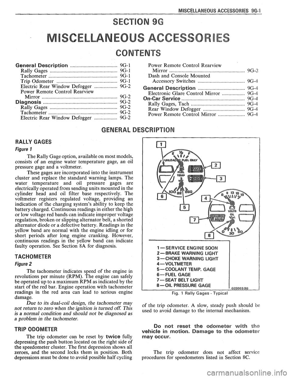
RALLY GAGES
Figure I
The Rally Gage option, available on most models,
consists of an engine water temperature gage, an oil
pressure gage and a voltmeter.
These gages are incorporated into the instrument
cluster and replace the standard warning lamps. The
water temperature and oil pressure gages are
electrically operated from sending units mounted in the
cylinder head and oil filter base respectively. The
voltmeter registers regulated voltage, providing an
indication of the charging system's ability to keep the
battery charged. Continuous readings in either the high
or low voltage red bands can indicate improper voltage
regulation, broken or slipping alternator belt,
a shorted
alternator diode
or a defective battery. Readings in the
yellow band are normal with the engine idling or for
short periods after long engine cranking. However,
continuous readings in the yellow band can indicate
faulty operation. See Section
8A for diagnosis.
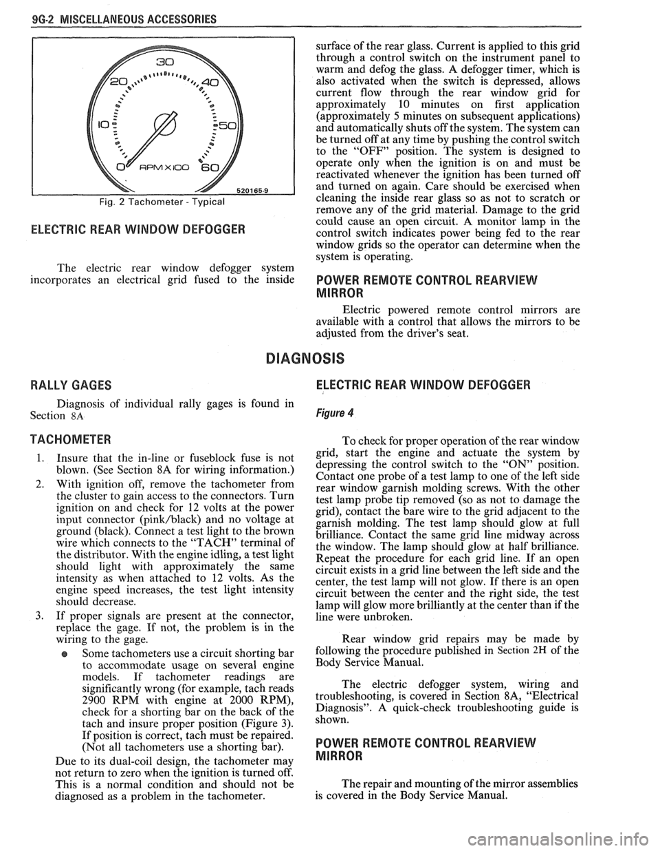
TACHOMETER
Figure 2
The tachometer indicates speed of the engine in
revolutions per minute (RPM). The engine can safely
be operated up to a maximum RPM as indicated by the
start of the red bar. Engine operation with tachometer
readings in the red area can lead to serious engine
damage.
Due to its dual-coil design, the tachometer may
not return to zero when the ignition
is turned oft: This
is
a normal condition and should not be diagnosed as
a problem in the tachometer.
TRIP ODOMETER
The trip odometer can be reset by twice fully
depressing the push button located on the right side of
the speedometer cluster. The first depression shows all
zeroes, and the second locks them in position. Both
depressions must be done to avoid possible half cycling
I -SERVICE ENGINE SOON
2-BRAKE WARNING LIGHT
3-CHOKE WARNING LIGHT
4-VOLTMETER
5-COOUNT TEMP. GAGE
6-FUEL GAGE
7-SEAT BELT LIGHT
8-OIL PRESSURE GAGE G20003 9G
Fig. 1 Rally Gages - Typical
of the trip odometer. A slow, steady push should be
used to avoid damage to the internal mechanism.
Do not reset the odometer with the
vehicle in motion. Damage to the odometer
may occur.
The trip odometer does not affect service
procedures for speedometers listed in Section
8C.
Page 1675 of 1825
9G-2 MISCELLANEOUS ACCESSORIES
Fig. 2 Tachometer - Typical
RPMX I00 €31-
ELECTRIC REAR WINDOW DEFOGGER
surface of the rear glass. Current is applied to this grid
through a control switch on the instrument panel to
warm and defog the glass. A defogger timer, which is
also activated when the switch is depressed, allows
current flow through the rear window grid
for
approximately 10 minutes on first application
(approximately
5 minutes on subsequent applications)
and automatically shuts off the system. The system can
be turned off at any time by pushing the control switch
to the "OFF" position. The system is designed to
operate only when the ignition is on and must be
reactivated whenever the ignition has been turned off
and turned on again. Care should be exercised when
cleaning the inside rear glass so as not to scratch or
remove any of the grid material. Damage to the grid
could cause an open circuit. A monitor lamp in-the
control switch indicates power being fed to the rear
window grids so the operator can determine when the
system is operating.
The electric rear window defogger system
incorporates an electrical grid fused to the inside
POWER REMOTE CONTROL REARVIEW
MIRROR
Electric powered remote control mirrors are
available with a control that allows the mirrors to be
adjusted from the driver's seat.
RALLY GAGES ELECTRIC REAR WINDOW DEFOGGER
Diagnosis of individual rally gages is found in
Section
8A Figure 4
TACHOMETER To check for moper o~eration of the rear window
1. Insure that the in-line or fuseblock fuse is not
blown. (See Section 8A for wiring information.)
2. With ignition off, remove the tachometer from
the cluster to gain access to the connectors. Turn
ignition on and check for
12 volts at the power
input connector
(pink/black) and no voltage at
ground (black). Connect a test light to the brown
wire which connects to the "TACH" terminal of
the distributor. With the engine idling, a test light
should light with approximately the same
intensity as when attached to
12 volts. As the
engine speed increases, the test light intensity
should decrease.
3. If proper signals are present at the connector,
replace the gage. If not, the problem is in the
wiring to the gage.
Some tachometers use a circuit shorting bar
to accommodate usage on several engine
models. If tachometer readings are
significantly wrong (for example, tach reads
2900 RPM with engine at 2000 RPM),
check for a shorting bar on the back of the
tach and insure proper position (Figure
3).
If position is correct, tach must be repaired.
(Not all tachometers use a shorting bar).
Due to its dual-coil design, the tachometer
may
- grid, start the engine a& actuate the system by
depressing the control switch to the
"ON" position.
Contact one probe of a test lamp to one of the left side
rear window garnish molding screws. With the other
test lamp probe tip removed (so as not to damage the
grid), contact the bare wire to the grid adjacent to the
garnish molding. The test lamp should glow at full
brilliance. Contact the same grid line midway across
the window. The lamp should glow at half brilliance.
Repeat the procedure for each grid line. If an open
circuit exists in a grid line between the left side and the
center, the test lamp will not glow. If there is an open
circuit between the center and the right side, the test
lamp will glow more brilliantly at the center than if the
line were unbroken.
Rear window grid repairs may be made by
following the procedure published in
Section 2H of the
Body Service Manual.
The electric defogger system, wiring and
troubleshooting, is covered in Section
8A, "Electrical
Diagnosis". A quick-check troubleshooting guide is
shown.
POWER REMOTE CONTROL REARVIEW
MIRROR
not return to zero when tvhe ignition is turned off'.
This is a normal condition and should not be The
repair and mounting of the mirror assemblies
diagnosed as a problem in the tachometer. is
covered in the Body Service Manual.
Page 1677 of 1825
96.4 MISCELLANEOUS ACCESSORIES
DASH AND CONSOLE MOUNTED ACCESSORY
SWITCHES
Installation for various dash and console
mounted accessory switches is shown in Section
8C.
GENERAL DESCRIPIIOM
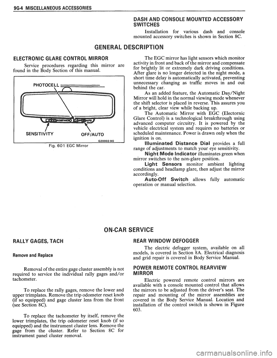
ELECTRONIC GLARE CONTROL MIRROR
Service procedures regarding this mirror are
found in the Body Section of this manual.
Fig. 601 EGC Mirror
The EGC mirror has light sensors which monitor
activity in front and back of the mirror and compensate
for brightly lit or extremely dark driving conditions.
After glare is no longer detected in the night mode, a
short time delay is automatically activated, preventing
unnecessary changing as traffic moves in and out
behind the car.
As an added feature, the Automatic
Day/Night
Mirror will hold in the normal viewing mode whenever
the shift selector is placed in reverse. This assures you
of a bright, clear view while backing up.
The Automatic Mirror with EGC (Electornic
Glare Control) is a technological breakthrough using
advanced computer circuitry. It is powered by the
vehicle electrical system and requires no batteries or
scheduled maintenance. Power is drawn only when the
ignition is on.
Illuminated Distance Dial provides a full
range of adjustments to match your eye sensitivity.
Night Mode Indicator illuminates green when
mirror switches to the non-glare position.
Light Sensors monitor ambient lighting
conditions and
headlamp glare, then adjust the mirror
accordingly.
Auto-Off Switch allows fully automatic
operation or manual selection.
ON-CAR SERVICE
RALLY GAGES, TACH REAR WINDOW DEFOGGER
Remove
and Replace
The electric defogger system, available on all
models, is covered in Section
8A. Electrical diagnosis
and grid repair is covered in Body Service Manual.
Removal of the entire gage cluster assembly is not
POWER RmOTE CONTROL REARVIEW
required to service the individual rally gages and/or MIRROR
tachometer.
Electric powered remote control mirrors are
available with a console mounted control that allows
To replace the rally gages, remove the lower and the
mirrors to be adjusted from the driver's seat. The
upper trimplates. Remove the trip odometer reset knob repair
and mounting of the mirror assemblies are
(if so equipped) and gage cluster lens from the front covered in
the Body Service Manual. Location and
(see Section
8C). installation of the control switch is shown in Figure
603.
To replace the tachometer by itself, remove the
lower trimplates, the trip odometer reset knob (if so
equipped) and the instrument cluster lens. Remove the
gage from the cluster. Refer to Section
8C for
hstrument panel cluster removal.
Page 1703 of 1825
2H-6 STATIONARY GLASS - F STYLE
all traces of factory installed adhesive must be
removed prior to reinstallation.
5. Wipe sanded mirror support with clean paper
towel saturated with alcohol and allow to dry.
6. Follow directions on manufacturer's kit to
prepare
rearview mirror support prior to
installation on glass.
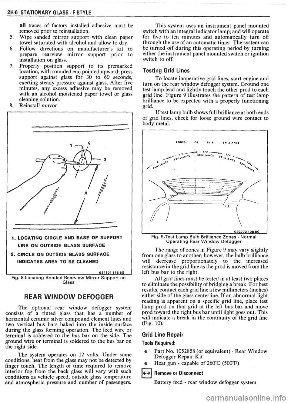
7. Properly position support to its premarked
location, with rounded end pointed upward; press
support against glass for 30 to 60 seconds,
exerting steady pressure against glass. After five
minutes, any excess adhesive may be removed
with an alcohol moistened paper towel or glass
cleaning solution.
8. Reinstall mirror
4. LOCATING CIRCLE AND BASE OF SUPPORT
LINE ON OUTSIDE GLASS SURFACE
2. CIRCLE ON OUTSIDE GLASS SURFACE
INDICATES AREA TO BE CLEANED
G94301-11 B.BG
Fig. 8-Locating Bonded earv view Mirror Support on
Glass
REAR WlMBOW DEFOGGER
The optional rear window defogger system
consists of a tinted glass that has a number of
horizontal ceramic silver compound element lines and
two vertical bus bars baked into the inside surface
during the glass forming operation. The feed wire or
terminal is soldered to the bus bar on the side. The
ground wire or terminal is soldered to the bus bar on
the right side.
The system operates on 12 volts. Under some
conditions, heat from the glass may not be detected by
finger touch. The length of time required to remove
interior fog from the back glass will vary with such
conditions as vehicle speed, outside glass temperature
and atmospheric pressure and number of passengers. This
system uses an instrument panel mounted
switch with an integral indicator lamp; and will operate
for five to ten minutes and automatically turn off
through the use of an automatic timer. The system can
be turned off during this operating period by turning
either the instrument panel mounted switch or ignition
switch to off.
Testing Grid Lines
To locate inoperative grid lines, start engine and
turn on the rear window defogger system. Ground one
test lamp lead and lightly touch the other prod to each
grid line. Figure
9 illustrates the pattern of test lamp
brilliance to be expected with a properly functioning
grid.
If test lamp bulb shows full brilliance at both ends
of grid lines, check for loose ground wire contact to
body metal.
Fig. 9-Test Lamp Bulb Brilliance Zones - Normal
Operating Rear Window Defogger
The range of zones in Figure 9 may vary slightly
from one glass to another; however, the bulb brilliance
will decrease proportionately to the increased
resistance in the grid line as the prod is moved from the
left bus bar to the right.
All grid lines must be tested in at least two places
to eliminate the possibility of bridging a break. For best
results, contact each grid line a few millimeters (inches)
either side of the glass centerline. If an abnormal light
reading is apparent on a specific grid line, place test
lamp prod on that grid at the left bus bar and move
prod toward the right bus bar until light goes out. This
will indicate a break in the continuity of the grid line
(Fig.
10).
Grid Line Repair
Tools Required:
o Part No. 1052858 (or equivalent) - Rear Window
Defogger Repair Kit
e Heat gun - capable of 260°C (500°F)
Remove or Disconnect
Battery 'feed - rear window defogger system