ECU PONTIAC FIERO 1988 Service Repair Manual
[x] Cancel search | Manufacturer: PONTIAC, Model Year: 1988, Model line: FIERO, Model: PONTIAC FIERO 1988Pages: 1825, PDF Size: 99.44 MB
Page 22 of 1825
MAINTENANCE AND LUBRICATION OB-5
Throttle linkage inspection -- Inspect for inter-
ference, binding, damaged or missing parts.
Engine drive belts inspection - Inspect all
belts for cracks, fraying and wear. Adjust or replace as
needed.
Rear axle service (if equipped) - Check gear
lubricant level and add if needed. For cars equipped with a
limited slip rear axle, fluid does not require changing
(except Caprice and Corvette
- change fluid and required
additive at first
7,500 miles (12 500 km). See your
Owner's Manual or "Recommended Fluids
& Lubricants
Chart" in this section.
IF YOU USE YOUR GAR TO PULL A TRAILER,
CHANGE GEAR LUBRICANT EVERY 7,500 MILES
(12 500 KM).
NOTICE: A large loss in this system may indicate a
problem. Have it inspected and repaired at once.
Power antenna - Clean and then lubricate power
antenna mast. The proper lubricant as shown in Figure
OB-2 should be used.
AT LEAST ONCE A YEAR
Lap and shoulder belts condition and opera-
tion
- Inspect belt system, including webbing, buckles,
latch plates, retractors, guide loops and anchors.
Moveable head restraint operation - On cars
with moveable restraints, make sure restraints stay in the
desired position. (See adjustment instructions in your
Owner's Manual.)
Seatback latch and recliner operation on
cars equipped
with recliner seat --- Be sure seat-
backs latch on those cars with folding seats using mechan-
ical latches. Make sure the recliner is holding by pushing
and pulling on the top of the
seatback while it is reclined.
See your Owner's Manual for seat operating information.
Spare tire and jack storage- Be alert to rattles
in rear of car. Make sure the space tire, all jacking equip-
ment, any tire inflator and any covers or doors are securely
stowed at all times. Oil jack ratchet or screw mechanism
after each use.
Key lock service - Lubricate key lock cylinder at
least annually.
Body lubrication service - Lubricate all body
door hinges including the tailgate or hatchback lid (if
equipped). Also lubricate the body hood, fuel door and
rear compartment hinges and latches including interior
glove box and counsel doors, and any folding seat
hardware.
"Fansmissionltransaxle neutral or clutch
starl switch operation
CAUnON: Before pedorming the follow-
ing safety switch check, be sure to have
enough room around the car. Then, firmly
apply both the parking brake (see your
Owner's Manual for procedure) and the
regular brakes. Do not use the accelerator pedal.
If the engine
starls, be ready to turn
off the ignition promptly. Take these pre-
cautions because the car could move
without warning and possibly cause per-
sonal injury or properly damage. On auto-
matic transmissionltransaxle cars, try to
starl the engine in each gear. The starler
should crank only in "Park" or "Neutral."
On manual transmissionltransaxle cars,
place the
shiR lever in "Neutral," push the
clutch halfway and try to starl. The starler
should crank only when the clutch is fully
depressed.
Steering column lock operation
- While
parked, try to turn key to "Lock" in each gear range. The
key should turn to "Lock" only when gear is in "Park" on
automatic or "Reverse" on manual
transmissionltransax-
le. On cars with key release lever, try to turn key toULock"
without depressing the lever. The key should turn to
"Lock" only with the key lever depressed. On all vehicles,
the key should come out only in "Lock."
Parking brake and transmissionltransaxle
"Park" mechanism operation
CAUT1ON:Before checking the holding
ability of the parking brake and automatic
transmissionltransaxle "Park" mecha-
nism, park on a fairly steep hill with
enough room for movement in the down-
hill direction. To reduce the risk of person-
al injury or property damage, be prepared
to apply the regular brakes promptly if the
car begins to move.
To check the parking brake, with the engine running and
transmission/transaxle in "Neutral." slowly remove foot
pressure from the regular brake pedal (until the car is held
by only the parking brake).
To check the automatic transmissionltransaxle "Park"
mechanism holding ability, release all brakes after shift-
ing the transmissionltransaxle to "Park."
ljnderbody flushing - At least every spring,
tlush from the underbody with plain water any corrosive
materials used for ice and snow removal and dust control.
Take care to thoroughly clean any areas where mud and
other debris can collect.
Sediment packed in closed areas
of the vehicle should be loosened before being flushed.
Engine cooling system service - Inspect
coolant and freeze protection. If dirty or rusty, drain, flush
and refill with new coolant. Keep coolant
at the proper
mixture as specified in your Owner's Manual. This pro-
vides proper freeze protection. corrosion inhibitor level
and engine operating temperature. Inspect hoses and re-
place if cracked. swollen or deteriorated. Tighten hose
clamps. Clean outside of radiator and air conditioning
condensor. Wash radiator filler cap and neck.
To help
ensure proper operation. a pressure test of both the cooling
system and cap is also recommended. (See maintenance
schedule charts in Figure
OB-l for the recommended
coolant change interval.)
Page 80 of 1825
W-4 AIR CONDITIONING COMPRESSOR OVERHAUL 1 Dl-l
SECTION 1 Dl
R COND NG COMPRESSOR
OVERHAUL
For Compressor REMOVAL AND INSTALLATION, see Air Conditioning Section 1B. For
DISCHARGING, ADDING OIL, EVACUATING AND CHARGING PROCEDURES FOR
A/C
SYSTEMS, see Air Conditioning Section 1B.
CONTENTS
General Description ............................... 1D1-1
Service Procedures .................................. 1D1-4
Minor Repair Procedures ....................... 1D1-4
Clutch Plate and Hub Assembly ............... 1D1-4
Clutch Rotor and Bearing: Four-Pole
Clutch
..................................................... 1D1-5
Clutch Rotor and Bearing: Six-Pole
Clutch
.......................... ... ....................... 1 D 1-7
Clutch Coil and Pulley Rim ...................... 1 D 1 - 10
Major Repair Procedures ....................... 1D1-12
Shaft Seal .................................................. 1Dl-12
Seal Leak Detection ........................... .... 1D1-12
Replacement (On Car) ........................... 1 D 1- 12
Replacement (Off Car)
........................... 1 D 1 - 13
Pressure Relief Valve
................................. 1 D 1 - 13
Nigh Pressure Cut-Off Switch
................... 1 D 1 - 13
Front Head and 0-Ring
............................ 1 D 1 - 14
Thrust and Belleville Washers
................... 1 D 1 - 16
Main Bearing
.............................................. 1 D 1- 16
Shell and 0-Ring
....................................... 1D 1- 17
Discharge Valve Plate and Retainer
......... 1 D 1 - 18
Cylinder and Shaft Assembly
.................... 1 D 1 - 19
Leak Testing (External and Internal)
........ 1D1- 19
Special Tools ..................................... ... .. 1D1-21
GENERAL DESCRIPTION
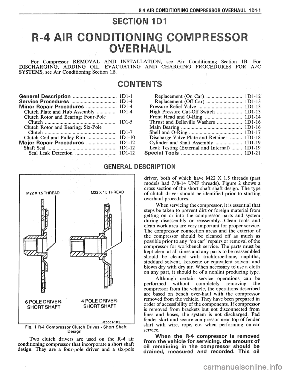
M22 X 1.5 THREAD M22 X 1.5 THREAD
6 POLE DRIVER- 4 POLE DRIVER-
SHORT SHAFT SHORT SHAFT
J20001.1 Dl
Fig. 1 R-4 Compressor Clutch Drives - Short Shaft
Desian
driver, both of which have M22 X 1.5 threads (past
models had 7/8-14
UNF threads). Figure 2 shows a
cross section of the short shaft shaft design. The type
of clutch driver should be identified prior to starting
overhaul procedures.
When servicing the compressor, it is essential that
steps be taken to prevent dirt or foreign material from
getting on or into the compressor parts and system
during disassembly or reassembly. Clean tools and
clean work area are very important for proper service.
The compressor connection areas and the exterior of
the compressor should be cleaned off as much as
possible prior to any "on car" repairs or removal of the
compressor for workbench service. The parts must be
kept clean at all times and any parts to be reassembled
should be cleaned with trichloroethane, naphtha,
stoddard solvent, kerosene or equivalent solvent and
blown dry with dry air. When necessary to use a cloth
on any part, it should be of a nonlint producing type.
Although certain service operations can be
performed without completely removing the
compressor from the vehicle, the operations described
are based on bench over-haul with the compressor
removed from the vehicle. They have been prepared in
order of accessibility of the components. If compressor
is removed from brackets but not disconnected from
lines and hoses, the system is not discharged. Pad
fender skirt and secure compressor near top of fender
skirt with wire, rope,
etc, when performing on-car
service.
., When the R-4 compressor is removed Two 'lutch drivers are wed On the R-4 air from the vehicle for servicing, the amount of conditioning compressor that incorporate a short shaft oil remaining in the should be design. They are a four-pole driver and a six-pole drained, measured and recorded. This oil
Page 85 of 1825
1 D1-6 R-4 AIR CONDITIONING COMPRESSOR OVERHAUL
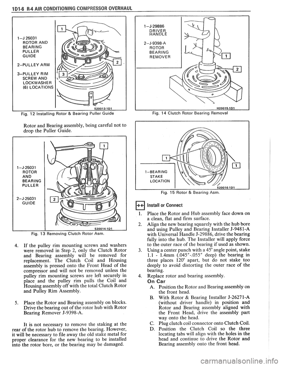
I-J 25031
ROTOR AND
BEARING
PULLER
GUIDE
2-PULLEY ARM
3-PULLEY RIM SCREW AND
LOCKWASHER
(6) LOCATIONS
Fig.
12 Installing Rotor & Bearing Puller Guide
Rotor and Bearing assembly, being careful not to
drop the Puller Guide.
1 -J-2503 1 ROTOR
AND BEARING
PULLER
2-J-25031 GUIDE
Fig.
13 Removing Clutch Rotor Asm.
4. If
the pulley rim mounting screws and washers
were removed in Step 2, only the Clutch Rotor
and Bearing assembly will be removed for
replacement. The Clutch Coil and Housing
assembly is pressed onto the Front Head of the
compressor and will not be removed unless the
pulley rim mounting screws are left securely in
place and the pulley rim pulls the Coil and
Housing assembly off with the total Clutch Rotor
and Pulley Rim Assembly.
5. Place the Rotor and Bearing assembly on blocks.
Drive the bearing out of the rotor hub with Rotor
Bearing Remover
J-9398-A.
It is not necessary to remove the staking at the
rear of the rotor hub to remove the bearing. However,
it will be necessary to file away the old stake metal for
proper clearance for the new bearing to be installed
into the rotor bore, or the bearing may be damaged.
1 -J-29886
2-J-9398-8
REMOVER
Fig.
14 Clutch Rotor Bearing Removal
Fig.
15 Rotor & Bearing Asm.
Install or Connect
1. Place the Rotor and Hub assembly face down on
a clean, flat and firm surface.
2. Align
the new bearing squarely with the hub bore
and using Pulley and Bearing Installer
5-9481-A
with Universal Handle 5-29886, drive the bearing
fully into the hub. The Installer will apply force
to the outer race of the bearing if used as shown.
3. Using
a center punch with
a 45" angle point, stake
1.1
- 1.4mm (.045"-.055" deep) the bearing in
three places 120" apart, but do not stake too
deeply to avoid distorting the outer race of the
bearing.
4. Replace
rotor and bearing assembly.
On Car
A. Position the Rotor and Bearing assembly on
the front head.
B. With Rotor
& Bearing Installer J-26271-A
(without driver handle) in position and
Rotor and Bearing assembly aligned with
the Front Head, drive the assembly part
way onto the head.
C. Plug clutch coil connector onto Clutch Coil.
D. Position the Clutch Coil so the three
locating tabs will
align with the holes in the
head and continue to drive the Rotor and
Bearing assembly onto the front head.
Page 91 of 1825
4 Dl-I 2 R-4 AIR CONDITIONING COMPRESSOR OVERHAUL
MAJOR REPAIR PROCEDURES
Service repair procedures to the
Compressor Shaft Seal,
Pressure Relief Valve
or disassembly
of the Internal Compressor
Cylinder and Shaft Assembly are considered
"MAJOR" SINCE THE REFRIGERATION
SYSTEM MUST BE DISCHARGED,
EVACUATED AND RECHARGED to complete
service and/or because major internal
operating and sealing components of the
compressor are being disassembled and
serviced.
When replacing the shaft seal assembly or
pressure relief valve, even if the compressor remains on
the vehicle during the operation, it will be necessary to
discharge the system of refrigerant (see Section
1B).
Other than clutch repair procedures, the same holds
true for any disassembly of the compressor.
If the compressor shell, front head or cylinder
and shaft assembly are to be serviced or replaced, the
oil in the compressor must be drained, measured and
replaced (see Section
1B) to determine addition of
proper oil quantity to new assembly.
A clean workbench, preferably covered with a
sheet of clean paper, orderliness in the work area and
a place for all parts being removed and replaced is of
great importance, as is the use of the proper, clean
service tools.
NOTICE: Any attempt to use make-shift or
inadequate equipment may result in damage
and/or improper compressor operation.
All parts required for servicing the internal
compressor are protected by a preservation process and
packaged in a manner which will eliminate the
necessity of cleaning, washing or flushing of the parts.
The parts can be used in the internal assembly just as
they are removed from the service package.
Seals and
protective packaging should be left in tact un
ti1 just
prior to installation.
SI-IAFT SEAL
Fig. 35 thru 40
Shaft Seal Design
The shaft seal is a one piece design.
Seal Leak Detection
A shaft seal should not be changed because of an
oil-line on the hood insulator. The Seal is designed to
seep some oil for lubrication purposes. Only change a
Shaft Seal when a leak is detected by evidence of oil
sprayed in large amounts and then only after actual
refrigerant leakage is found by using an approved leak
Detector such as J-29547 or equivalent.
Should an R-4 compressor shaft seal ever have to
be replaced, the accumulator in this R-4 system must
also be removed from the vehicle. The oil in the
accumulator then must be drained, measured and
replaced according to the directions in Section
1B to
determine oil loss.
On-Car
Remove
or Disconnect
1. Discharge A/C system
2. Loosen and reposition compressor in mounting
brackets
3. Clutch Plate and Hub assembly
4. Shaft seal seat retainer ring, using Snap Ring
Pliers J-5403-A
5. Thoroughly clean inside of compressor neck area
and O-ring groove surrounding the shaft, the
exposed portion of the seal seat and the shaft
itself. Any dirt or foreign material getting into
compressor may cause damage.
6. Remove Lip Seal:
e Fully engage the knurled tangs of Seal
Remover-Installer J-23 128-A into the
recessed portion of the Seal by turning the
handle clockwise. Remove the Seal from the
compressor with a rotary-pulling motion.
Discard the Seal. The handle must be
hand-tightened securely. Do not use a
wrench or pliers.
7. Discard the seal seat O-ring from the compressor
neck using 0-Ring Remover J-9553-01.
8. Recheck the shaft and inside of the compressor
neck and O-ring groove for dirt or foreign
material and be sure these areas are perfectly
clean before installing new parts.
Inspection
Seals should not be reused. Always use a new
specification service seal kit on rebuild. Care should be
taken to prevent damage to the lip of the one piece seal.
Make sure that the Seal Seat and Seal Lip are free of
lint and dirt that could damage the seal surface or
prevent sealing.
On-Car
Install
or Connect
1. Dip
the new seal O-ring in clean 525 viscosity
refrigerant oil and assemble onto 0-Ring
Installer J-33011.
2. Insert
the 0-Ring Installer
5-3301 1 completely
down into the compressor neck until the Installer
"bottoms." Lower the moveable slide of the
0-Ring Installer to release the 0-Ring into the
seal seat O-ring lower groove. (The compressor
neck top groove is for the shaft seal retainer ring.)
Rotate the Installer to seat the O-ring and remove
the Installer.
3. Prepare Lip Seal:
Assemble seal to Seal Installer J-23128-A,
by turning handle clockwise, and then push
Seal Protector J-34614, into seal lip. The
stamped steel case side of the lip seal must
be engaged with knurled tangs of installer so
that flared-out side of lip seal is facing and
installed towards the compressor.
4. Install Lip Seal:
Page 110 of 1825
CHASSIS SHEET METAL 2C-3
3. Allow hood to open, and tighten latch bolts in
new location.
FENDER PANEL
An outer fender panel with a plastic inner panel
is used. Care should be used in handling raw fenders
due to the lack of fender rigidity prior to installation.
Body surfaces at molding areas must be cleaned
thoroughly with suitable organic solvent immediately
prior to installation to ensure adhesion. Do not allow
adhesive surface of molding to come in contact with
wet solvent, dirt, or foreign matter.
NO"FICE: If heat source is used to condition
moldings prior to installation, the source is to
provide
uniform heating, not to exceed 85°F.
Application is to be made in a clean area with
ambient and body surface temperatures of at least
65°F.
The moldings are to be secured with two appli-
cations of a force of 20 pounds for the full length of
each section using a roller or other suitable tool.
Any section of molding removed once in contact
with the body surface must be replaced.
ALUMINUM PANEL REPAIR PROCEDURES
An aluminum hood (inner and outer panel) is
used on some vehicles. An aluminum panel can be
identified by checking it with a magnet, preferably in
the front corners to avoid any possible damage to the
paint. Aluminum will not attract a magnet.
Aluminum panels can be repaired successfully
with only slight changes of materials and techniques
commonly used to refinish steel panels. The necessary
modifications fall into two categories: 1) metal
preparation; and 2) painting.
Metal Preparation
1. Because aluminum is relatively easy to grind,
care must be taken not to use overly coarse abra-
sive discs or excessive grinder speeds (greater
than 2,000 rpm), both of which will cause
excessive heat and unnecessary metal removal.
2. Surface scratches should normally be removed
with 180 or 120 grit paper with scalloped edges.
Hand sanding with 80 grit paper will usually be
sufficient to remove excessive body filler or
heavy scratches, again followed with 180 grit
paper.
NOTICE: Avoid scratching aluminum when
sanding with 80 grit paper by hand.
3. Foam backed pads are recommended for
grinders used on aluminum, rather than the
stiffer rubber pads used for mounting abrasive
discs used on steel. The foam pad helps to
reduce heat build-up and improves blending for
feathering.
4. Localized heat, generated by grinding, can be
minimized by the use of a grease stick, such as
Formax F-160 or equivalent. This does, how-
ever, tend to load up the grinding discs quickly,
which should be periodically cleaned by rotating
them against a brush wetted with solvent.
5. If out-dings or minor convex defects need to be
filed, it is recommended to use a round edge,
double cut, flexible file with 22 teeth per inch
overlaid with 52 teeth per inch (such as
Nicholson
#50-412 or equivalent).
NOTICE: Keep file clean so that chips do not
scratch aluminum.
The use of heat is not recommended, since the
structural characteristics of aluminum are noticeably
affected by heat. A bent or buckled aluminum hood,
which exhibits strain cracks either before or after
straightening, should be replaced.
Both steel and aluminum panels can be metal
prepped and repaired with two-part polyester filler
materials in the same number of operations. The only
differences are that less aggressive type files and abra- sive discs should be used, with care being taken not to
overheat the aluminum.
Painting
Painting procedures for aluminum panels differ
very little from those used on steel panels. Two pre-
cautions should, however, be observed:
1. Alkaline base paint removers are not recom-
mended and should not be used.
2. Aluminum also requires a chemical cleaner such
as
DuPont 2253, Ditzler DX-533, or equivalent
be used on bare metal to remove contaminants
and corrosion. After cleaning, a conversion
coating such as DuPont
226S, Ditzler DX-503
or equivalent should be applied to promote
adhesion.
Beyond these considerations, painting alumi-
num panels should present no increases in difficulty or
changes in procedure and technique.
PAINTING AND REPAIRING NONMETAL
EXTERIOR PARTS 1
FiberglassIABS Plastic Panel Repair ~
A Plastic Solder Repair Kit can be used to repair
cracks, dents, or pits in fiberglass or ABS panels. A
Glass Woven Cloth should be installed on the under
side of a crack in the panel to structurally reinforce the
panel. The following procedure can be used to repair
the panels:
1. With a lacquer removing solvent, remove paint
from damaged area down to the fiberglass or
, ABS material. I
2. Scuff-sand area surrounding damaged area to
provide a good bonding surface.
Page 153 of 1825
385-2 STEERING WHEELS AND COLUMNS
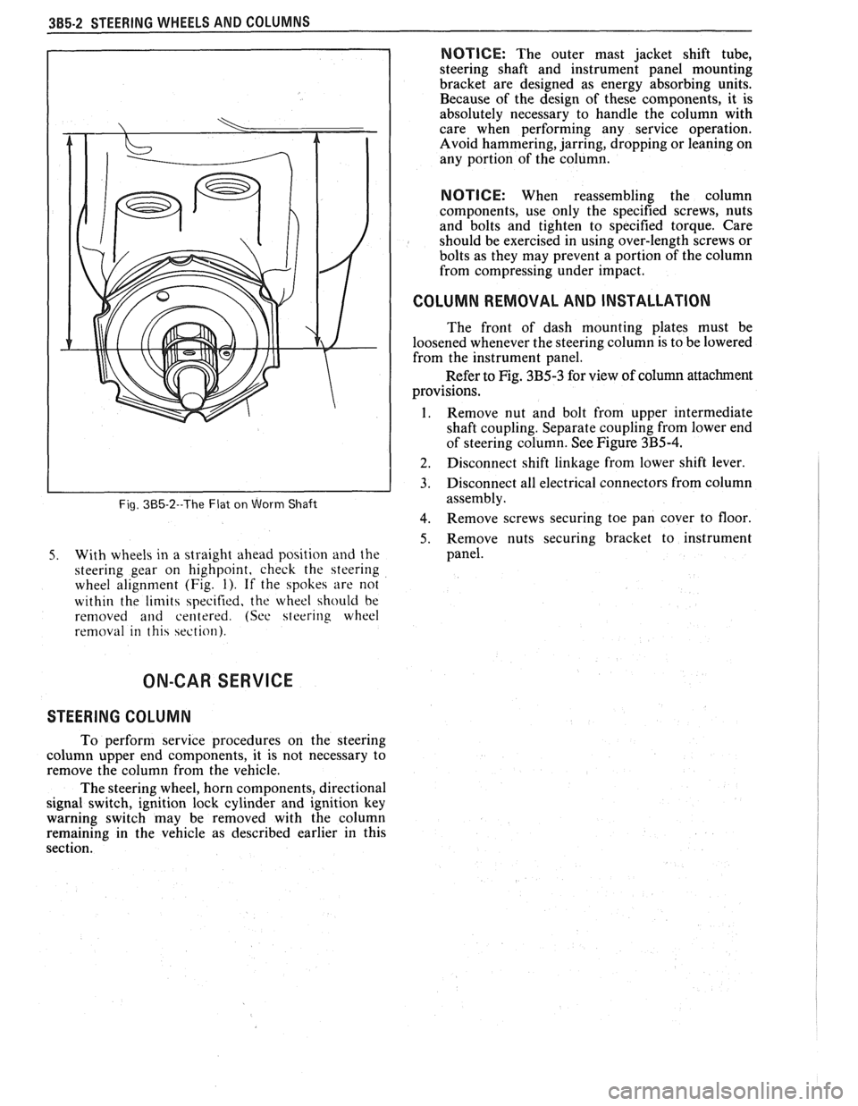
Fig. 385-2--The Flat on Worm Shaft
5. With wheels in a straight ahead position and the
steering gear on highpoint, check the steering
wheel alignment (Fig.
1). If the spokes are not
within the
limits specified, the wheel should be
removed
and centered. (See steering wheel
removal in this section).
NOTICE: The outer mast jacket shift tube,
steering shaft and instrument panel mounting
bracket are designed as energy absorbing units.
Because of the design of these components, it is
absolutely necessary to handle the column with
care when performing any service operation.
Avoid hammering, jarring, dropping or leaning on
any portion of the column.
NOTICE: When reassembling the column
components, use only the specified screws, nuts
and bolts and tighten to specified torque. Care
should be exercised in using over-length screws or
bolts as they may prevent a portion of the column
from compressing under impact.
I COLUMN REMOVAL AND INSTALLATION
The front of dash mounting plates must be
loosened whenever the steering column is to be lowered
from the instrument panel.
Refer to Fig. 3B5-3 for view of column attachment
provisions.
1. Remove nut and bolt from upper intermediate
shaft coupling. Separate coupling from lower end
of steering column. See Figure
3B5-4.
] 2. Disconnect shift linkage from lower shift lever.
3. Disconnect all electrical connectors from column
assembly.
4. Remove screws securing toe pan cover to floor
5. Remove nuts securing bracket to instrument
panel.
ON-CAR SERVICE
STEERING COLUMN
To perform service procedures on the steering
column upper end components, it is not necessary to
remove the column from the vehicle.
The steering wheel, horn components, directional
signal switch, ignition lock cylinder and ignition key
warning switch may be removed with the column
remaining in the vehicle as described earlier in this
section.
Page 166 of 1825
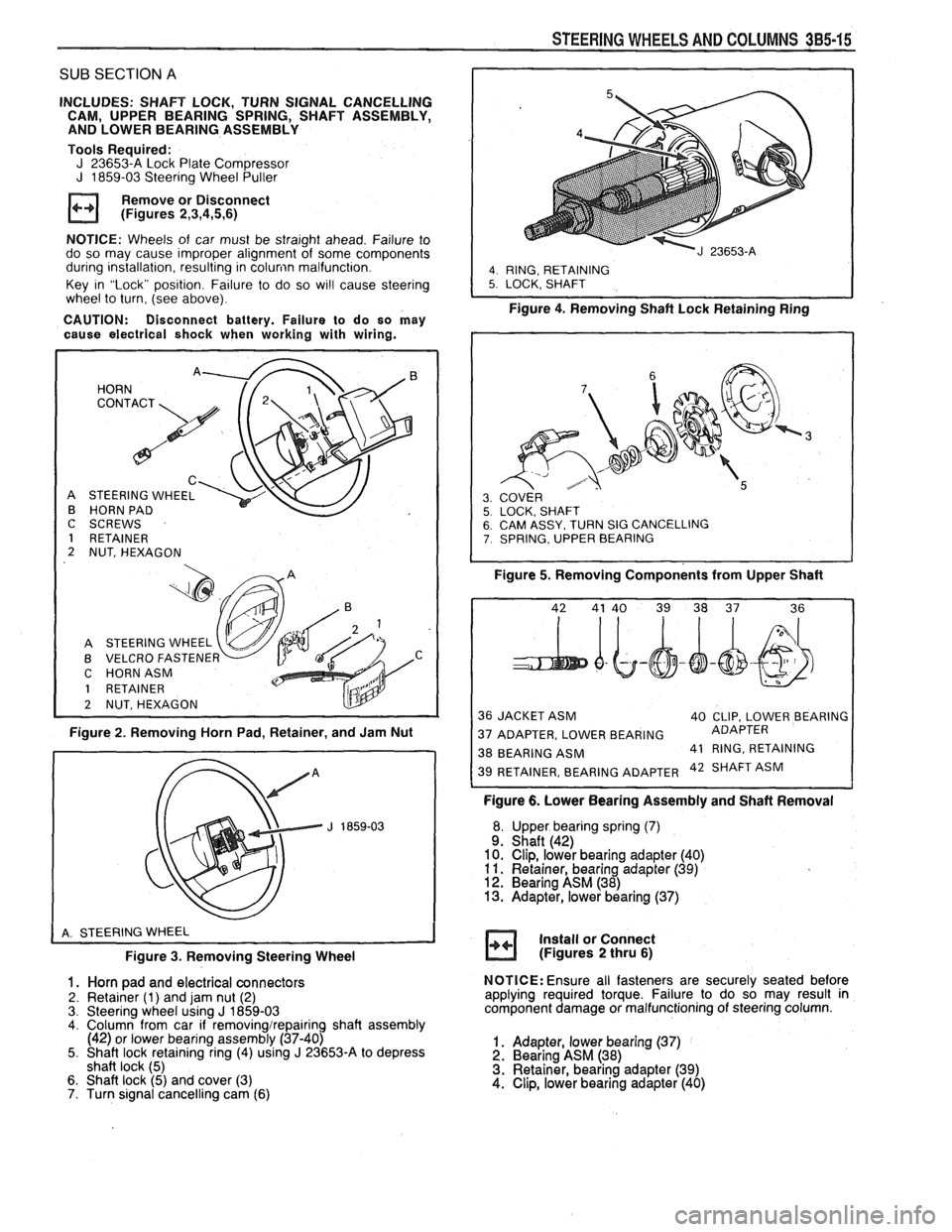
SUB SECTION A
INCLUDES: SHAFT LOCK, TURN SIGNAL CANCELLING
CAM, UPPER BEARING SPRING, SHAFT ASSEMBLY,
AND LOWER BEARING ASSEMBLY
Tools Required:
J 23653-A Lock Plate Compressor J 1859-03 Steering Wheel Puller
Remove or Disconnect
(Figures
2,3,4,5,6)
NOTICE: Wheels of car must be straight ahead. Failure to
do so may cause improper alignment of some components
during installation, resulting in
colunin malfunction.
Key in "Lock" position. Failure to do so
wi!l cause steering
wheel to turn, (see above).
CAUTION: Disconnect battery. Failure to do so may
cause electrical shock when working with wiring.
HORN
C
STEERING WHEEL
HORN PAD
I
C SCREWS
1 RETAINER
2 NUT, HEXAGON
A STEERING WHEEL
B VELCRO
FASTENEF v C HORNASM
1 RETAINER
2 NUTSHEXAGON
Figure 2. Removing Horn Pad, Retainer, and Jam Nut
Figure
3. Removing Steering Wheel
1. Horn pad and electrical connectors
2. Retainer (1) and jam nut (2)
3. Steering wheel using J 1859-03 4. Column from car if removingirepairing shaft assembly
(42) or lower bearing assembly (37-40)
5. Shaft lock retaining ring (4) using
J 23653-A to depress
shaft lock (5)
6. Shaft lock (5) and cover (3)
7. Turn signal cancelling cam (6)
STEERING WHEELS AND COLUMNS 385-15
I
4. RING, RETAINING 5. LOCK. SHAFT
Figure 4. Removing Shaft Lock Retainingain;
SY. TURN SIG CANCELLING , UPPER BEARING
Figure 5. Removing Components from Upper Shaft
36 JACKET ASM
40 CLIP, LOWER BEARING
37 ADAPTER, LOWER BEARING ADAPTER
38 BEARING
ASM 41
RING, RETAINING 42 SHAFT ASM
Figure 6. Lower Bearing Assembly and Shaft Removal
Upper bearing spring
(7) Shaft (42)
Clip, lower bearing adapter (40)
Retainer, bearing adapter
(39) Bearing ASM (38) Adapter, lower bearing (37)
Install or Connect
(Figures
2 thru 6)
NOTICE: Ensure all fasteners are securely seated before
applying required torque. Failure to do so may result in
component damage or malfunctioning of steering column.
1. Adapter, lower bearing (37) 2. Bearing ASM (38)
3. Retainer, bearing adapter (39)
4. Clip, lower bearing adapter (40)
Page 167 of 1825
385-16 STEERING WHEELS AND COLUMNS
5. Shaft assembly (42) to column 6. Bearing spring (7)
7. Turn signal cancelling cam (6)
8. Shaft lock (5) and cover (3) 9. Shaft lock retaining ring (4) using J 23653-A to depress
shaft lock (5) 10. Column to dash 1 1. Steering wheel 12. Jam nut (2) 13. Retainer (1) 14. Horn pad
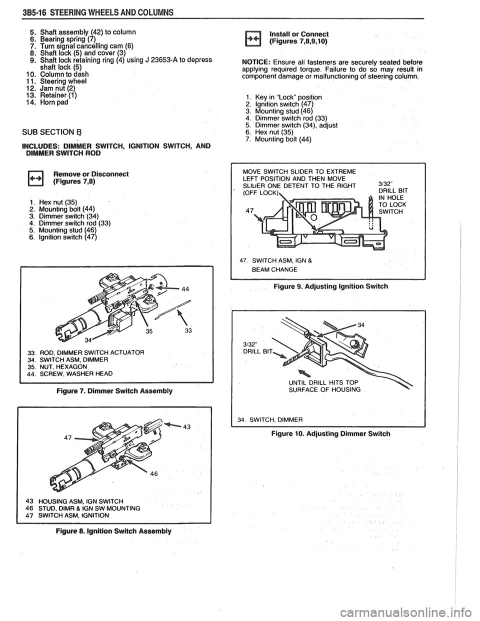
SUB SECTION Ej
INCLUDES: DIMMER SWITCH, IGNITION SWITCH, AND
DIMMER SWITCH ROD
Remove or Disconnect
(Figures
7,8)
1. Hex nut (35)
2. Mounting bolt (44)
3. Dimmer switch (34) 4. Dimmer switch rod (33)
5. Mounting stud (46)
6. lgnition switch (47)
Figure 7. Dimmer Switch Assembly
IGN SW MOUNTING
Figure 8. lgnition Switch Assembly install
or Connect
(Figures
7,8,9,10)
NOTICE: Ensure all fasteners are securely seated before
applying required torque. Failure to do so may result in
component damage or malfunctioning of steering column.
1. Key in "Lock" posit~sn 2. lgnltion switch (47)
3. Mounting stud (46)
4. Dimmer switch rod (33)
5. Dimmer switch (34), adjust 6. Hex nut (35) 7. Mounting bolt (44)
47 SWITCH ASM. IGN 8
Figure 9. Adjusting Ignition Switch
UNTIL DRILL HITS TOP
SURFACE OF HOUSING
34 SWITCH. DIMMER I
Figure 10. Adjusting Dimmer Switch
Page 168 of 1825
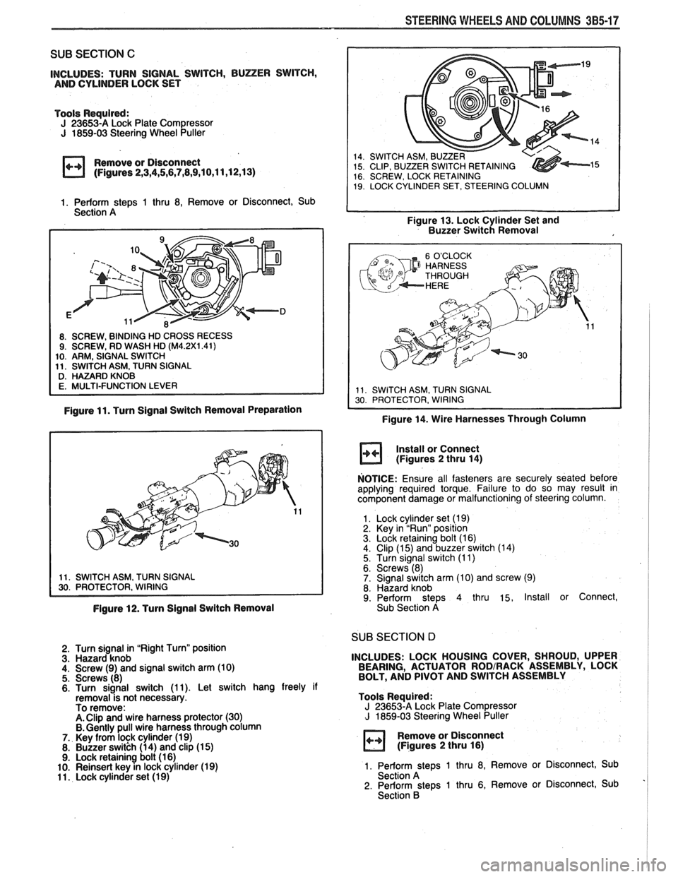
STEERING WHEELS AND COLUMNS 385-17
SUB SECTION C
INCLUDES: TURN SIGNAL SWITCH, BUZER SWITCH,
AND CYLINDER LOCK SET
Tools Required:
J 23653-A Lock Plate Compressor J 1859-03 Steering Wheel Puller
Remove or Disconnect
(Figures
2,3,4,5,6,7,8,9,10,11,12,13)
1. Perform ste~s 1 thru 8, Remove or Disconnect, Sub
Section A
, STEERING COLUMN
Figure 13. Lock Cylinder Set and
Buzzer Switch Removal
Figure 11. Turn Signal Switch Removal Preparation
Figure 14. Wire Harnesses Through Column
Install or Connect
(Figures
2 thru 14)
NOTICE: Ensure all fasteners are securely seated before
applying required torque. Failure to do so may result In
component damage or malfunctioning of steering column.
1. Lock cylinder set (1 9)
2. Key in "Run" position 3. Lock retaining bolt (16) 4. Clip (15) and buzzer switch (14)
5. Turn signal switch (1 1) 6. Screws (8) 7. Signal switch arm (1 0) and screw (9) 8. Hazard knob 9. Perform steps 4 thru 15, Install or Connect,
Figure 12. Turn Signal Switch Removal Sub
Section A
SUB SECTION D I 2. Turn signal in "Right Turn" position 3. Hazard knob
4. Screw (9) and signal switch arm (10) 5. Screws (8)
6. Turn signal switch (1 1). Let switch hang freely if
removal-is not necessary.
To remove:
A. Clip and wire harness protector (30) B. Gently pull wire harness through column 7.. Key from lock cylinder (19)
8. Buzzer switkh (14) and clip (1 5) 9. Lock retaining bolt (1 6)
10. Reinsert key in lock cylinder (19) 1 1. Lock cylinder set (19)
INCLUDES: LOCK HOUSING COVER, SHROUD, UPPER
BEARING, ACTUATOR RODIRACK ASSEMBLY, LOCK
BOLT, AND PIVOT AND SWITCH ASSEMBLY
Tools Required:
J 23653-A Lock Plate Compressor J 1859-03 Steering Wheel Puller
Remove or Disconnect
(Figures 2 thru 16)
1. Perform stem 1 thru 8, Remove or Disconnect, Sub
Section A ' 2. Perform steps 1 thru 6, Remove or Disconnect, Sub
Section B
Page 169 of 1825
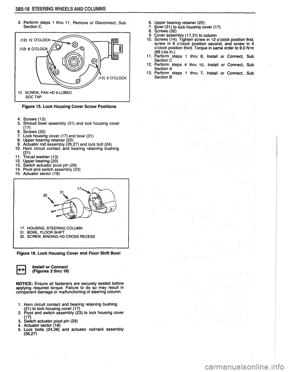
385-18 STEERING WHEELS AND COLUMNS
(12) 12 O'CLOCK
3. Perform steps 1 thru 11, Remove or Disconnect, Sub 6. Upper bearing retainer (22)
Section C 7. Bowl (31) to lock housing cover (17)
8. Screws (32)
9. Cover assembly (1
7,31) to column
10. Screws (14). Tighten screw in 12 o'clock position first,
screw in 8 o'clock position second, and screw in 4
o'clock position third. Torque in same order to 9.0
N.m (89 Lbs.ln.) 11. Perform steps 1 thru 8, Install or Connect, Sub
Section C 12. Perform steps 4 thru 15, Install or Connect, Sub
Section A
13. Perform steps 1 thru 7, Install or Connect, Sub
Section
B
Figure 15. Lock Housing Cover Screw Positions
4. Screws (12)
5. Shroud bowl assembly
(31) and lock housing cover 1171 6. ~c:dr'ews (32)
7. Lock housing cover (1 7) and bowl (31)
8. Upper bearing retainer (22)
9. Actuator rod assembly (26,27) and lock bolt (24)
10. Horn circuit contact and bearing retaining bushing
121 1 11. Yhiust washer (1 3) 12. Upper bearing (20)
13. Switch actuator pivot pin (29)
14. Pivot and switch assembly (23)
15. Actuator sector (1 8)
17. HOUSING, STEERING COLUMN 31. BOWL, FLOOR SHIFT 32. SCREW, BINDING HD CROSS RECESS
Figure 16. Lock Housing Cover and Floor Shin Bowl
Install
or Connect (Figures 2 thru 16)
NOTICE: Ensure all fasteners are securely seated before
applying required torque. Failure to do so may result in
component damage or malfunctioning of steering column.
1. Horn circuit contact and bearing retaining bushing
(21 ) to lock housing cover (1 7)
2. Pivot and switch assembly (23) to lock housing cover
(1 7) 3. Switch actuator pi~ot pin (29)
4. Actuator sector (1 8) 5. Lock bolts (2428) and actuator rodlrack assembly (26,271