turn signal PONTIAC FIERO 1988 Service Owner's Manual
[x] Cancel search | Manufacturer: PONTIAC, Model Year: 1988, Model line: FIERO, Model: PONTIAC FIERO 1988Pages: 1825, PDF Size: 99.44 MB
Page 180 of 1825
STEERING WHEELS AND COLUMNS 3B5-29
SUB SECTION A
INCLUDES: SHAm LOCK, TURN SIGNAL CANCELLlNG CAM, UPPER BEARING SPRING, UPPER BEARING
SEAT, INNER RACE TURN SIGNAL SWITCH, BUZZER
SWITCH,
AND LOCK CYLINDER SET
Tools
Requird: J 23653-A Lock Plate Compressor J 35689-A Terminal Remover
Remove or Disconnect
(Figure
,2,3,4,5,6,7,8,9)
NOTICE: Wheels of car must be straight ahead. Failure to
do so may cause improper alignment of some components
during installation, resulting in column malfunction.
Key in
"Lock position. Failure to do so will cause steering
wheel to turn, (see above).
CAUTION: Disconnect battery. Failure to do so may
cause electrical shock when working with wiring.
HORN '. 72' CONTACT
A STEERING WHEEL
B HORN PAD C SCREWS 1 RETAINER 2 NUT, HEXAGON
A STEERING WHEEL
B VELCRO FASTENER C HORNASM
1 RETAINER
2 NUT, HEXAGON L!lY -
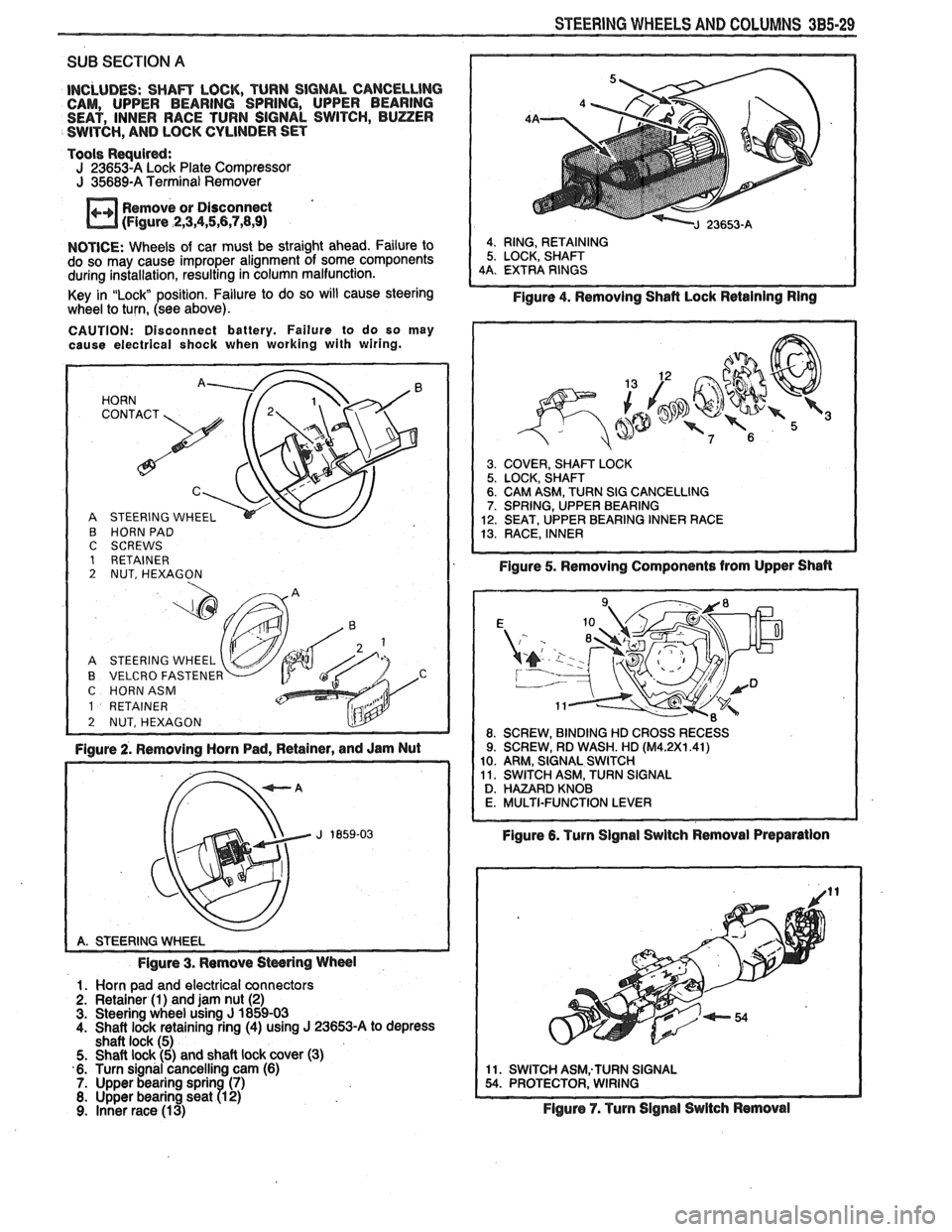
Figure 2. Removing Horn Pad, Retainer, and Jam Nut
Figure 3. Remove
Stwring Wheel
1. Horn pad and electrical connectors
2. Retainer (1) and jam nut (2) 3. Steering wheel using J 1859-03
4. Shaft lock retaining ring (4) using J 23653-A to depress
shaft lock (5)
5. Shaft lock (5) and shaft lock cover (3)
6. Turn signal cancelling cam (6)
7. Upper bearing sprin (7) 8. Upper bearing seat R 2) 9. Inner race (13)
4. RING, RETAINING
5. LOCK, SHAFT
4A. EXTRA RINGS
Figure 4. Removing Shafl Lock Retaining Ring
3. COVER, SHAm LOCK 5. LOCK, SHAFT 6. CAM ASM, TURN SIG CANCELLING 7. SPRING, UPPER BEARING
12. SEAT, UPPER BEARING INNER RACE
13. RACE, INNER
Figure 5. Removing Components from Upper Shan
Figure 6. Turn Signal Swltch Removal Preparation
11. SWITCH ASM;TURN SIGNAL 54. PROTECTOR, WIRING
Flgure 7. Turn Signal Switch Removal
Page 181 of 1825
385-30 STEERING WHEELS AND COLUMNS
10. Turn si nal to "Right Turn" position
11. Screw 79) and signal switch arm (10)
12. Screws (8)
13. Turn signal switch (11). Allow switch to hang freely if re-
moval is not necessary.
To remove:
A. Wiring protector (54)
B. Hazard knob
C.Gently pull wire harness through column housing
shroud (62), column housing (38), and lock housing
cover (1 8)
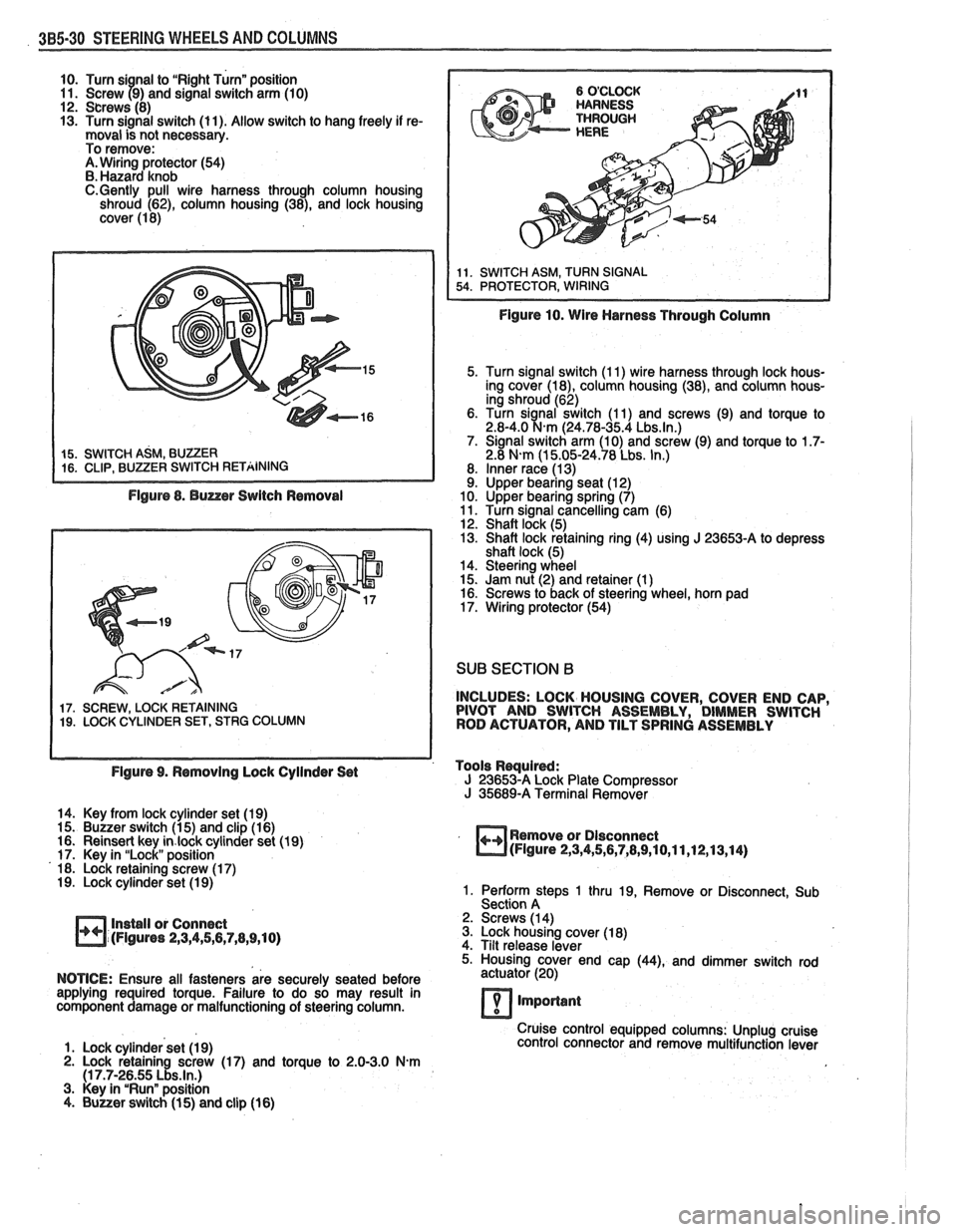
Figure 8. Buzzer Switch Removal
17. SCREW, LOCK RETAINING 19. LOCK CYLINDER SET, STRG COLUMN
Figure 10. Wire Harness Through Column
5. Turn signal switch (1 1) wire harness through lock hous-
ing cover
(la), column housing (38), and column hous-
ing shroud (62)
6. Turn
sianal switch (1 1) and screws (9) and torque to 2.8-4.0 %km (24.78-35.4 Lbs.ln.) 7. Signal switch arm (10) and screw (9) and torque to 1.7- 2.8 N-m (1 5.05-24.78 Lbs. In.)
8. Inner race (1 3) 9. Upper bearing seat (1 2)
10. Upper bearing spring (7)
11. Turn signal cancelling cam (6)
12. Shaft lock (5)
13. Shaft lock retaining ring (4) using
J 23653-A to depress
shaft lock (5)
14. Steering wheel
15. Jam nut (2) and retainer (1
) 16. Screws to back of steering wheel, horn pad
17. Wiring protector (54)
SUB SECTION B
INCLUDES: LOCK HOUSING COVER, COVER END CAP,
PIVOT AND SWITCH ASSEMBLY, DIMMER SWITCH
ROD ACTUATOR, AND TILT SPRING ASSEMBLY
Figure 9. Removing Lock Cyilnder Set Tools
Rwuired: J 23653-A Lock
Plate Compressor J 35689-A Terminal Remover
14. Key from lock cylinder set (19)
15. Buzzer switch (1 5) and clip (1 6)
16. Reinsert key
in.lock cylinder set (19)
17. Key in "Lock" position
18. Lock retaining screw (1 7)
19. Lock cylinder set (1 9)
Install or Connect
(Figures
2,3,4,5,6,7,8,9,10)
Remove or Dlsconnect (Figure 2,3,4,5,6,7,8,9,10,11,12,13,14)
1. Perform steps 1 thru 19, Remove or Disconnect, Sub
Section A
2. Screws (1 4)
3. Lock housing cover (1 8)
4. Tilt release lever
5. Housing cover end cap
(44), and dimmer switch rod
NOTICE: Ensure all fasteners are securely seated before actuator
(20)
applying required torque. Failure to do so may result in
component damage or malfunctioning of steering column.
7 important
Cruise control equipped columns: Unplug cruise
1. Lock cylinder set (1 9) control
connector and remove multifunction lever
2. Lock retaining screw (17) and torque to 2.0-3.0 N.m (1 7.7-26.55 Lbs.ln.) 3. Key in "Run" position
4. Buuer switch (1 5) and clip (16)
Page 186 of 1825
STEERING WHEELS AND COLUMNS 385.35
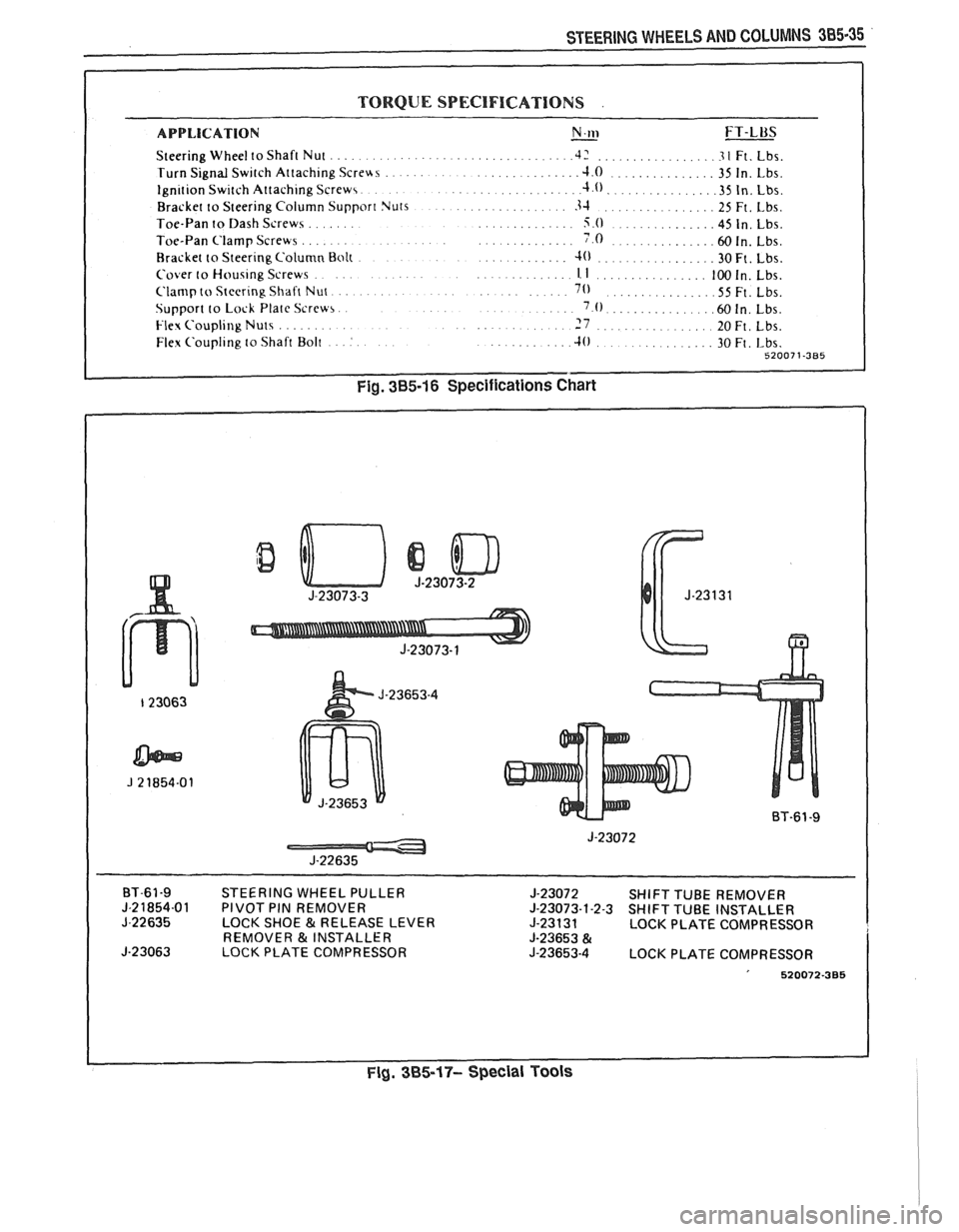
TORQUE SPECIFICATIONS .
APPLICATION N.w - FT-LUS
Steering Wheel to Shaft Nut .................................. .42 ................ .3 1 Ft. Lbs.
Turn Signal Switch Attaching
Screus ...................... .J.O ............... 35 In. Lbs.
.. Ignition Switch Attaching Screws. ................. .4.0.. ............. .35 In. Lbs.
Bracket to Steering Column Support Nuts
................. 3-1 ................ 25 Ft. Lbs.
....... Toe-Pan to Dash Screws .............. 5.0 .............. 45 In. Lbs.
....... .............. Toe-Pan Clamp Screws ..... 7.0 .............. .60 In. Lbs.
Bracket to Steering Column Bolt
............. 4) ................. 30Ft. Lbs.
.... Cover to Housing Screws . ,. . .............. 1. I ................ 100 In. Lbs.
..... Clamp to Steering Shaft Nut. ............. 70 ............... .55 Ft. Lbs.
Support to Lock Plate Screw,.
. . . ..... '.0. .............. ,150 In. Lbs.
......... Flex Coupling Nuts ........... 7 ................. 20~t. ~bs.
... Flex Coupling to Shaft Bolt : .......... .10 30 Ft, ~bs. .............. 52007 1-385
Fig. 385-16 Specifications Chart
BT-61-9 STEERING WHEEL PULLER
J-23072 SHIFT TUBE REMOVER J-21854-01 PIVOT PIN REMOVER J-23073-1-2-3 SHIFT TUBE INSTALLER
J-22635 LOCK SHOE & RELEASE LEVER
J-23131 LOCK PLATE COMPRESSOR
REMOVER & INSTALLER J-23653 & J-23063 LOCK PLATE COMPRESSOR J-23653-4 LOCK PLATE COMPRESSOR
' 520072-385
Fig. 385-17- Special Tools
Page 434 of 1825
ENGINE FUEL 6C.3
a Fuel feed and return pipes are secured to the
underbody with clamps and screw assemblies.
The pipes should be inspected occasionally for
leaks, kinks or dents.
e Follow the same routing as the original pipe.
e Pipes must be properly secured to the frame to
prevent chafing. A minimum of 6 mm
(1/4")
clearance must be maintained around a pipe to
prevent contact and chafing.
MPFl Fuel Pipes
Due to the fact that fuel pipes are under high
pressure, these systems require special consideration for service.
Many feed and return pipes use screw couplings
with
"0" Rings. Any time these fittings are loosened
to service or replace components, ensure that:
a A backup wrench is used while loosening and
tightening the fitting.
e Check all "0" rings at fitting locations (if
applicable) for cuts or any damage and replace
any that appear worn or damaged.
e Use correct torque when tightening fittings.
If pipes are replaced always use original
equipment parts, or parts that meet GM
specifications.
Fuel and Vapor Hoses
NOTICE: Fuel and vapor hoses are specially
manufactured. If replacement becomes necessary,
it is important to use only replacement hoses
meeting GM Specification 6163-M. These hoses
are identified with the words "Fluoroelastomer"
on them. Hoses not so marked could cause early
failure, or fail to meet emission standards.
e Do not use rubber hose within 4" of any part of
the exhaust system, or within
10" of the catalytic
converter.
FUEL PUMP
The electric fuel pump is in the fuel tank. The
tank has an outlet for a vapor return system. Any vapor
which forms is returned to the fuel tank along with hot
fuel through a separate line. This greatly reduces any
possibility of vapor lock by keeping cool fuel from the
tank constantly circulating through the fuel pump.
FUEL PUMP RELAY
To control fuel pump operation, a fuel pump
relay is used.
When the ignition switch is turned to "RUN"
position, the fuel pump relay activates the electric fuel
pump for
1.5 to 2.0 seconds to prime the injector(s). If
the ECM does not receive reference pulses from the
distributor after this time, the ECM signals the relay
to turn off the fuel pump. The relay will once again
activate the fuel pump when the
ECM receives
distributor reference pulses.
Fuel Filter
CAUTION: To reduce the risk of fire
and personal injury, it is necessary
to
relieve the fuel system pressure
before servicing fuel system
components. (See Fuel System
Pressure Relief.)
The inline filters can be found on the rear
crossmember of the vehicle. Always use a backup
wrench any time that the fuel filter is removed or
installed. Also make sure that a good
"0" Ring is used
at all screw couple locations. Torque on fittings is
30
N-m (22 lb. ft.).
FUEL TANK
The fuel tank is usually located under the rear of
the vehicle and a number of shapes and sizes are used
depending on the application.
The tank is held in place by two metal straps,
hinged (with a bolt through the hinge) and secured at
the opposite end with a nut and bolt assembly.
Anti-squeak pieces are used on top of the tank to
reduce rattles and other annoying noises.
The fuel tank, cap and lines should be inspected
for road damage, whch could cause leakage. Inspect
fuel cap for correct sealing and indications of physical
damage. Replace any damaged or malfunctioning
parts.
Before attempting service of any type on the fuel
tank, always
(1) remove negative battery cable from
battery, (2) place "no smoking" signs near work areas,
(3) be sure to have C02 fire extinguisher handy, (4)
wear safety glasses and
(5) siphon or pump fuel into an
explosion proof container.
Fuel Filler Gap
The fuel tank filler neck is equipped with a
screw-type cap. The threaded part of the cap requires
several turns counterclockwise to remove. The long
threaded area is designed to allow any remaining fuel
tank pressure to escape while the cap is being removed.
A built-in torque-limiting device prevents
overtightening. To install, turn the cap clockwise until
a clicking noise is heard. This signals that the correct
torque has been reached and the cap is fully seated.
N OTI G E: If a fuel filler cap requires replacement,
use only a cap with the same features. Failure to
use the correct cap can result in a serious
malfunction of the system.
Available on some models is an electric locking
fuel filler cap. Information on this option will be found
in Section
9E.
FUEL TANK FILLER NECK
To help prevent refueling with leaded gasoline,
the fuel filler neck on gasoline engine cars has a built-in
restrictor and deflector. The opening in the restrictor
will only admit the smaller unleaded gas nozzle spout,
which must be fully inserted to bypass the deflector.
Attempted refueling with a leaded gas nozzle or failure
Page 470 of 1825
IGNITION SYSTEM 6D4-1
ON SYSTEM
CONTENTS
General Description ............................... 6D4-1 Service Procedures ............................. 6D4-3
Ignition System .......................................... 6D4-1
Ignition System .......................................... 6D4-3
Distributor Ignition ................................ 6D4-1
Distributor Ignition ................................ 6D4 -3
Diannosis .................................................... 6D4-3 On-Car Service ......................................... 6D4-5 -
Ignition System .......................................... (334-3 Ignition System ........................... .. .............. 6D4-5
Distributor ................................................. 6D4 -7 HE1 Distributor .................................... 6D4-3
GENERAL DESCRIPION
The engine electrical system includes the battery,
ignition (primary and secondary), starter (and related
wiring) and the generator (and related wiring).
Diagnostic charts (see Section 6D) will aid in
trouble-shooting system faults. When a fault is traced
to a particular component, refer to that components'
section of the service manual.
IGNITION SYSTEM
Distributor Ignition
The ignition circuit consists of the battery,
distributor, ignition switch, spark plugs and primary
and secondary wiring. Refer to the Battery portion of
this section for battery information.
PIE1 Distributor
The Nigh Energy Ignition (HEI) distributor with
Electronic Spark Timing (EST), used on most engines,
combines all ignition components in one unit. The
ignition coil is in the distributor cap and connects
through a resistance brush to the rotor.
The distributor has an internal magnetic pick-up
assembly which contains a permanent magnet, a pole
piece with internal teeth and a pick-up coil. When the
teeth of the timer core, rotating inside the pole piece,
line up with the teeth of the pole piece, an induced
voltage in the pick-up coil signals the electronic module
to trigger the coil primary circuit. The primary current
decreases and a high voltage is induced in the ignition
coil secondary winding. This voltage is directed
through the rotor and secondary leads to fire the spark
plugs. The capacitor in the distributor is for radio noise
suppression,
All spark timing changes in the
HE1 (EST)
distributor are done electronically by an Electronic
Control Module (ECM), which monitors information
from various engine sensors, computes the desired
spark timing and signals the distributor to change the
timing accordingly.
A back-up spark advance system
is incorporated to signal the ignition module in case of
(ECM) failure. No vacuum or mechanical advance is
used. Further (EST) information is found in sections 6E
Emissions Control, and
8A Electrical
Troubleshooting.
Ignition Timing
Timing specifications for each engine are listed in
Section
6E. When using a timing light, connect an
adapter between the No. 1 spark plug and the No. 1
spark plug wire, or use an inductive type pick-up.
Do
not pierce the plug lead.
Once the insulation of the
spark plug cable has been broken, voltage will jump to
the nearest ground, and the spark plug will not fire
properly.
Always follow the tune-up label
procedures when adjusting timing.
Some engines will incorporate a magnetic timing
probe hole for use with special electronic timing
equipment. Fig.
1A shows a typical magnetic probe
hole. Consult manufacturer's instructions for use of
this equipment.
Secondary Wiring
The spark plug wiring used with ignition systems
is a carbon impregnated cord conductor, encased in an
8MM (5/16") diameter silicone rubber jacket. The
silicone jacket withstands very high temperatures and
also provides an excellent insulator for the higher
voltage of the
HE1 system. Silicone spark plug boots
form a tight seal on the plug.
The boot should be
twisted 1/2 turn before removing. Care should
also be exercised when connecting a timing light or
other pick-up equipment. Do not force anything
between the boot and wiring, or through the silicone
jacket. Connections should be made in parallel using
an adapter. DO NOT pull on the wire to remove. Pull
on the boot, or use a tool designed for this purpose.
Spark Plugs
Resistor type, tapered seat spark plugs are used
on all engines (except aluminum heads). No gasket is
used on these tapered seat plugs. See Figs.
1B and 1C
for an explanation of coding on spark plugs.
Normal service is assumed to be a mixture of
idling, slow speed, and high speed driving. Occasional
or intermittent high-speed driving is needed for good
Page 519 of 1825
6EZ-A-28 5.OL (VIN E) DRIVEABILITY AND EMISSIONS
FRONT VIEW OF CONNECTOR
5V REFERENCE
TO
MAP SENSOR
CODE 21
THROTLE POSITION SENSOR (TPS) CIRCUIT
(SIGNAL VOLTAGE HIGH)
5.OL (VIN E) "F" "SERIES ("FBI)
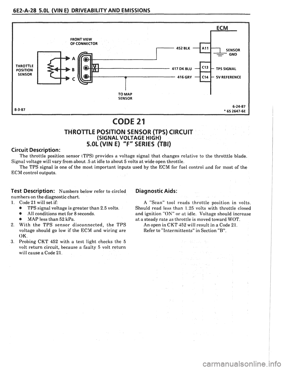
Circuit Description:
The throttle position sensor (TPS) provides a voltage signal that changes relative to the throtttle blade.
Signal voltage will vary from about
.5 at idle to about 5 volts at wide open throttle.
The TPS signal is one of the most important inputs used by the ECM for fuel control and for most of the
ECM control outputs.
Test Description: Numbers below refer to circled
numbers on the diagnostic chart.
1. Code
21 will set if:
@ TPS signal voltage is greater than 2.5 volts.
@ All conditions met for 8 seconds.
@ MAP less than 52 kPa.
2. With the TPS sensor disconnected, the TPS
voltage should go low if the ECM and wiring are
OK.
3. Probing CKT 452 with a test light checks the 5
volt return circuit, because a faulty 5 volt return
will cause
a Code 21.
Diagnostic Aids:
A ''Scan" tool reads throttle position in volts.
Should read less than 1.26 volts with throttle closed
and ignition
"Oili" or at idle. Voltage should increase
at a steady rate as throttle is moved toward
WOT.
An open in CKT 152 will result in a Code 21.
Refer to
"Intermittents" in Section "B".
Page 525 of 1825
6EZ-A-34 5.OL (WIN E) DRIVEABILITY AND EMISSIONS
ECM
I.P.
8RN 437
K 7 PIN SIGNAL
PIN SWITCH
r ELK450 12v
1 CLOSED IN - 15- WAY .I.P. CONNECTOR - - PARK OR NEUTRAL I
CODE 24
VEHICLE SPEED SENSOR (VSS) CIRCUIT
5.OL (VIN E) "F" SERIES (TBI)
Circuit Description:
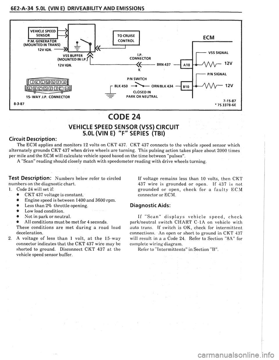
The ECM applies and monitors 12 volts on CKT 437. CKT 437 connects to the vehicle speed sensor which
alternately grounds CKT
437'when drive wheels are turning. This pulsing action takes place about 2000 times I
per mile and the ECM will calculate vehicle speed based on the time between "pulsesJ'.
A "Scan" reading should closely match with speedometer reading with drive wheels turning.
I
Test Description: Numbers below refer to circled
numbers on the diagnostic chart.
1. Code 24 will set if:
@ CKT 437 voltage is constant.
@ Engine speed is between 1400 and 3600 rpm.
@ Less than 2% throttle opening.
@ Low load condition.
@ Not in park or neutral.
@ All conditions must be met for 4 seconds.
These conditions are met during a road load
deceleration.
2.
A voltage of less than 1 volt, at the 15-way
connector indicates that the CKT 437 wire
may be
shorted to ground.
Disconnect CKT 437 at the
vehicle speed sensor buffer. If
voltage remains less than 10 volts, then CKT
437 wire is grounded or open.
If 437 is not
grounded or open, check for a faulty
KCYI
connector or ECM.
Diagnostic Aids:
If "Scan" displays vehicle speed, check
parWneutra1 switch CHART C-LA on vehicle with
auto trans.
If switch is OK, check for intermittent
connections.
An open or short to ground in CKT 437
will result in
a a Code 24. Refer to Section "$A" for
col~lplete wiring diagram.
Refer to
"[ntermittents" in Section "B".
Page 537 of 1825
CODE 43
ELECTRONIC SPARK CONTROL (ESC) CIRCUIT
5.0L (VIN E) "F" SERIES (TBI)
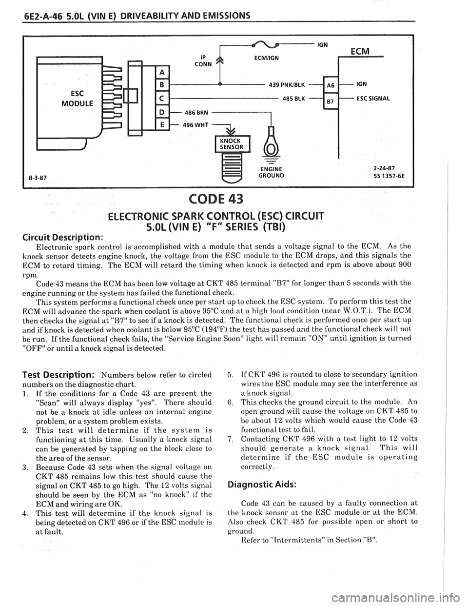
Circuit Description:
Electronic spark control is accomplished with a module that sends a voltage signal to the ECM. As the
knock sensor detects engine knock, the voltage from the ESC module to the ECM drops, and this signals the
ECM to retard timing. The ECM will retard the timing when knock is detected and rpm is above about 900
rpm. Code 43 means the ECM has been low voltage at CKT 485 terminal
"B7" for longer than 5 seconds with the
engine running or the system has failed the functional check.
This system performs a functional check once per start up to check the ESC system. To perform this test the
ECM will advance the spark when coolant is above 95°C and at
a high load condition (near W.O.T.). The ECM
then checks the signal at
"B7" to see if a knock is detected. The functional check is performed once per start up
and if knock is detected when coolant is below 95°C (194°F) the test has passed and the functional check will not
be run. If the functional check fails, the "Service Engine Soon" light will
remain "ON" until ignition is turned
"OFF" or until a knock signal is detected.
Test Description: Numbers below refer to circled
numbers on the diagnostic chart.
1. If the conditions for a Code 43 are present the
"Scan" will always display "yes". There should
not be a knock at idle unless an internal engine
problem, or a system problem exists.
2. This test will determine if the system is
functioning at this time. Usually a
knock signal
can be generated by tapping on the block close to
the area of the sensor.
3. Because Code 43 sets when the signal voltage on
CKT 485 remains low this test should cause the
signal on CKT 485 to go high. The
12 volts signal
should be seen by the ECM as "no knock"
it' the
ECM and wiring are OK.
4.
This test will determine if the knock signal is
being detected on CKT 496 or if the ESC module is
at fault. 5.
If
CKT 496 is routed to close to secondary ignition
wires the ESC
module may see the interference as
a knock signal.
6. This checks the ground circuit to the module. An
open ground will cause the voltage on CKT 485 to
be about
12 volts which would cause the Code 43
functional test to fail.
7. Contacting
CKT 496 with a test light to
12 volts
should generate a knock signal.
This will
determine if the ESC nodule is operating
correctly.
Diagnostic Aids:
Code 43 can be caused by a faulty connection at
the knock sensor at the ESC
lnodule or at the ECM.
Also check CKT 485 for possible open or short to
ground.
Iiefer to "Intcrmittents" in Section "B".
Page 543 of 1825
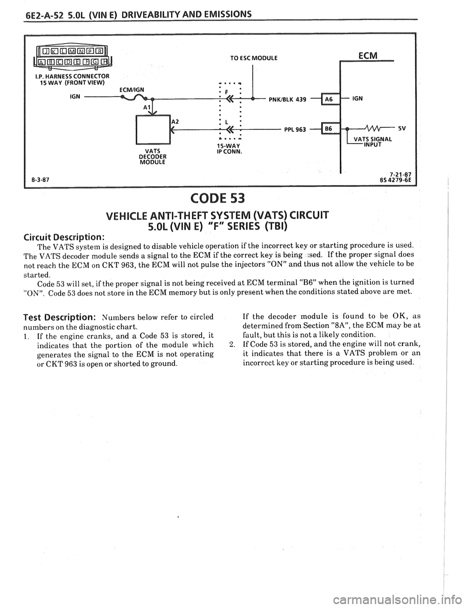
PNWBLK 439
CODE 53
VEHICLE ANTI-THEFT SYSTEM (VATS) CIRCUIT
5.OL (VIM E) "F" SERIES (TBI)
Circuit Description:
The VATS system is designed to disable vehicle operation if the incorrect key or starting procedure is used.
The VATS decoder module sends a signal to the ECM if the correct key is being
:sed. If the proper signal does
not reach the ECM on CKT 963, the ECM will not pulse the injectors
"ON" and thus not allow the vehicle to be
started. Code
53 will set, if the proper signal is not being received at ECM terminal "B6" when the ignition is turned
"ON". Code 53 does not store in the ECM memory but is only present when the conditions stated above are met.
Test Description: Numbers below refer to circled If the decoder module is found to be OK, as
numbers on the diagnostic chart. determined
from Section
"SA", the ECM may be at
1. If the engine cranks, and a Code 53 is stored, it Fault,
but this is not a likely condition.
indicates that the portion of the module which
2. If Code 53 is stored, and the engine will not crank,
generates the signal to the ECM is not operating it indicates
that there is a VATS problem or an
or CKT 963 is open or shorted to ground. incorrect
key or starting procedure is being used.
Page 545 of 1825
6E2-A-54 5.OL (VIN E) DRIVEABILITY AND EMISSIONS
465 DK GRNMlHT
450 BLWHT
FUEL PUMP BATTERY JUNCTION TEST TERM. BULKHEAD BODY CONNECTOR
BLOCK (12 VOLT) CONNECTOR
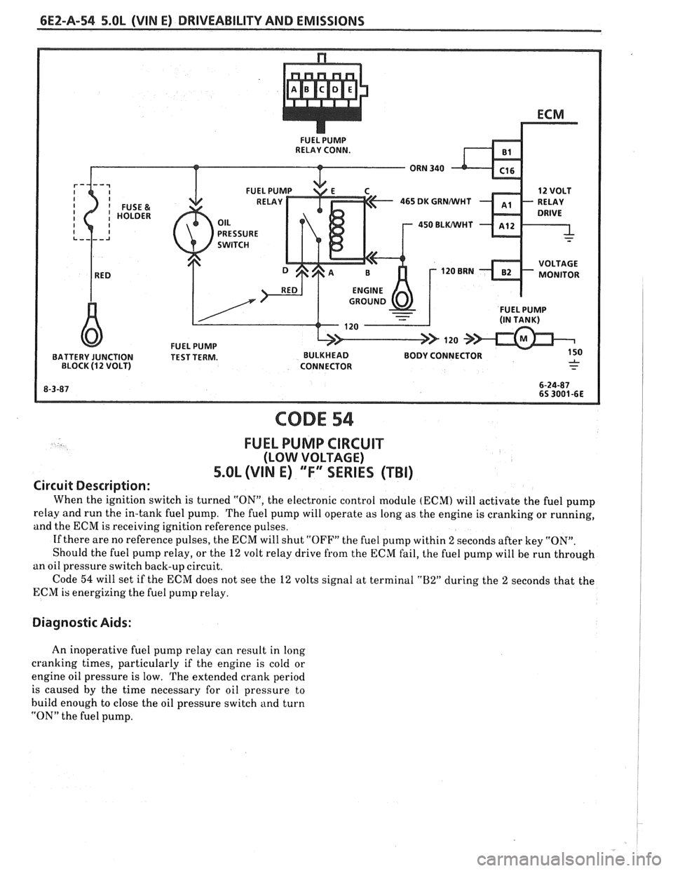
CODE 54
FUEL PUMP CIRCUIT
(LOW VOLTAGE)
5.OL (VIN E) "F"" SERIES (TBI)
Circuit Description:
When the ignition switch is turned "ON", the electronic control module (ECM) will activate the fuel pump
relay and run the in-tank fuel pump. The fuel pump will operate as long as the engine is cranking or running,
and the ECM is receiving ignition reference pulses.
If there are no reference pulses, the ECM will shut
"OFF" the fuel pump within 2 seconds after key "ON".
Should the fuel pump relay, or the
12 volt relay drive from the ECM fail, the fuel pump will be run through
an oil pressure switch back-up circuit.
Code
54 will set if the ECM does not see the 12 volts signal at terminal "B2" during the 2 seconds that the
ECM is energizing the fuel pump relay.
Diagnostic Aids:
An inoperative fuel pump relay can result in long
cranking times, particularly if the engine is cold or
engine oil pressure is low. The extended crank period
is caused by the time necessary for oil pressure to
build enough to close the oil pressure switch and turn
"ON" the fuel pump.