check engine PONTIAC FIERO 1988 Service Repair Manual
[x] Cancel search | Manufacturer: PONTIAC, Model Year: 1988, Model line: FIERO, Model: PONTIAC FIERO 1988Pages: 1825, PDF Size: 99.44 MB
Page 1167 of 1825
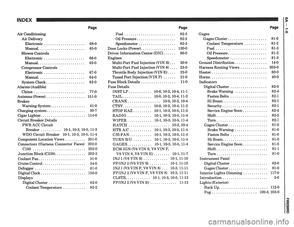
Page
Air Conditioning
Air Delivery
Electronic
.................... 68-0
Manual
....................... 65-0
Blower Controls
Electronic
.................... 66-0
Manual
....................... 63-0
Compressor Controls Electronic
.................... 67-0
Manual
....................... 64-0
................... System Check 62-0
Alarms (Audible)
Chime
......................... 77-0
Antenna(Power) ................... 151-0
Brakes
................. Warning System 41-0
................... Charging system 30-7
...................... Cigar Lighter 114-0
Circuit Breaker Details
PWR ACC Circuit
.......... Breaker 10.1.10.3.10.5.1 1.3
WDO Circuit Breaker
10.1. 10.3. 10.5. 11-4
.......... Component Location Views 201-0
Connectors (Harness Connector Faces) 202-0
el00 .......................... 202-0
............... Junction Block ((2238) 202-2
Coolant Fan
....................... 31-0
Cruise Control
..................... 34-0
Defogger
......................... 61-0
Digital Clock
...................... 150-0
Displays Digital Cluster
.................. 82-0
Coolant Temperature
........... 82-2
Page
......................... Fuel 82-3
................... Oil Pressure 82-2
.................. Speedometer 82-3
................. Door Locks (Power) 130-0
...... Driver Information Center (DIC) 86-0
Engines
... Multi-Port Fuel Injection (VIN S) 20-0
.... Multi-Port Fuel Injection (VIN 8) 23-0
.... Throttle
Body Injection (VIN E) 22-0
...... Tuned
Port Injection (VIN F) 21-0
................. Fuse Block Details 11-0
Fuse Details
........... INST LP 10.0.10.2.10.4.1 1.1
.............. TAIL 10.0.10.2.10.4.1 1.2
................ CRANK 10.0.10.2.1 0.4
.............. CTSY 10~0.10.2.10.4.1 1.2
......... STOP HAZ 10.1.10.3.10.5.1 1.3
............ RADIO 10.1.10.3.10.5.1 1.4
............ WIPER 10.1.10.3.10.5.1 1.4
.................... HATCH 10.2.1 0.4
........... HTR AlC 10.1.10.3.10.5.1 1.4
........... CIH.FAN 10.1.10.3.10.5.1 1.4
......... TURN BIU 10.1.10.3.10.5.1 1.4
............ GAGES 10.1.10.3.10.5.1 1.4
ECM-IGN
(V6 VIN S. V8 VIN F.
........ V8 VIN 8. V8 VIN E) 10.1.1 1.7
............ INJ 1 (V6 VIN S) 10.1.1 1.10
......... FPIINJ 2 (V6 VIN S) 10.1.1 1.10
... INJ 1 (V8 VIN F. V8 VIN 8) 10.3.1 1.11
FPIINJ 2 (V8 VIN F. V8 VIN 8) 10.3.1 1.11
............ CLSTR 10.1.10.3.10.5.1 1.13
............. FPIINJ 2 (V8 VIN E) 11-12
Page
Gages
................... Gages Cluster 81-0
........... Coolant Temperature 81-2
......................... Fuel 81-3
................... Oil Pressure 81-2
.................. Speedometer 81-3
................ Ground Distribution 14-0
Harness Routing Views
............. 203-0
........................... Heater 60-0
............................ Horns 40-0
Indicators
.................. Digital Cluster 82-0
................ Brake Warning 82-4
.................. Fasten Belts 82-1
...................... Hi Beam 82-1
...................... Security 82-1
............ Service Engine Soon 82-4
......................... Shift 82-5
......................... Turn 82-1
................... Gages Cluster 81-0
................ Brake Warning 81-0
.................. Fasten Belts 81-0
...................... Hi Beam 81-0
............ Service Engine Soon 81-0
......................... Shift 81-1
......................... Turn 81-0
Instrument Panel
Digital Cluster
.................. 82-0
Gages Cluster
................... 81-0
............ Interior Lights Dimming 117-0
...................... Introduction 2-0
Lights (Exterior)
........................ Back Up 112-0
...................... Fog 100.3,10 3.0
Page 1169 of 1825
INTRODUCTION 1:
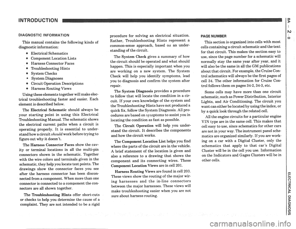
This manual contains the following kinds of
diagnostic information:
e Electrical Schematics
Component Location Lists
@ Harness Connector Faces
@ ?koubleshooting Hints
@ System Checks
System Diagnoses
@ Circuit Operation Descriptions
@ Harness Routing Views
Using these elements together will make elec-
trical troubleshooting faster and easier. Each
element is described below.
The Electrical
Seher~latic should always be
your starting point in using this Electrical
Troubleshooting Manual. The schematic shows
the electrical current paths when a circuit is
operating properly. It is essential to under-
stand how a circuit
should work before trying to
figure out why it doesn't.
The Harness Connector Faces show the cav-
ity or terminal locations in all the multi-pin
connectors shown in the schematic. Together
with the wire colors and terminals given in the
schematic, they help you locate test points. The
drawings show the connector faces you see
after the harness connector has been discon-
nected from a component. When more than one
connector is connected to a component the con-
nectors are all shown together.
The Troubleshooting Hints offer short-cuts
or checks to help you determine the cause of
a
complaint. They are not intended to be a rigid procedure
for solving an electrical situation.
Rather, Troubleshooting Nints represent a
common-sense approach, based on an under-
standing of the circuit.
The System Check gives a summary of how
the circuit should be operated and what should
happen. This is especially important when you
are working on a new system. The System
Check will help you identify symptoms, lead
you to diagnosis and confirm the system after
repair.
The System Diagnosis provides a procedure
to follow that will locate the condition in a cir-
cuit. If your own knowledge of the system and
the Troubleshooting Hints have not produced
a
quick fix, follow the System Diagnosis. All pro-
cedures are based on symptoms to assist you in
locating the condition as fast as possible.
The Circuit Operation will help you under-
stand the circuit. It describes the components
and how the circuit works.
The Component Location List helps you find
where the parts of the circuit are in the vehicle.
A brief statement of the location is given and
also a reference to a drawing that shows the
component and its connecting wires. These
Colnponent Location Views are in cell 201.
Harness Routing Views are found in cell 203.
These views show the routing of the major wir-
ing harnesses and the in-line connectors
between the major harnesses. These views will
make troubleshooting easier when you are not
sure about harness routing.
PAGE NUMBER
This section is organized into cells with most
cells containing a circuit schematic and the text
for that circuit. This makes the section easy to
use, since the page number for a schematic will
normally stay the same year after year, and it
will also be the same in
all the GM publications
about that circuit. For example, the Cruise Con-
trol schematics will always be the first pages of
cell 34. The other information for Cruise Con-
trol follows them on pages
34-2,34-3, etc.
Some cells may have more than one circuit
schematic, such as Power Distribution, Interior
Lights, and Air Conditioning. The circuit you
want can either be located by using the index, or
by a quick look through the related cell.
All the engine circuits for a particular engine
VIN type are in the same cell. This makes that
cell easy to use, since schematics for other cars
are not in your way. The instrument panel sche-
matics are organized similarly. If you are work-
ing on a car with a Digital Cluster, only the
schematics that apply to that car's Digital
Cluster will be in the cell you use. Information
on the Indicators and Gages Clusters will be in
other cells.
Page 1296 of 1825
TROUBLESHOOTING HINTS
STARTER
Try the following checks before doing
the Sys-
tem Diagnosis
.
1 . Check the hydrometer eye that is built into
the vehicle Battery before troubleshooting
the Starter System
.
. Green eye . Battery is charged .
. Dark eye . Battery is discharged . Recharge
Battery
.
- Clear or yellow eye . Battery fluid is low .
Replace Battery .
2 . Check that the Starter Solenoid te
and B and battery
connections are clean and
tight
.
3 . Check that grounds 6100 and 6103 are
clean and tight
.
Go to System Diagnosis for diagnostic tests .
SYSTEM DIAGNOSIS
STARTER
NOTE:
The following tests are designed for
engines and batteries at normal operat-
ing temperatures and assumes that
there are no engine symptoms which
could cause a no start condition
. To use
the tests under other conditions could
result in misdiagnosis
.
Diagnostic steps for the symptorns listed in
the following table are listed after the table
.
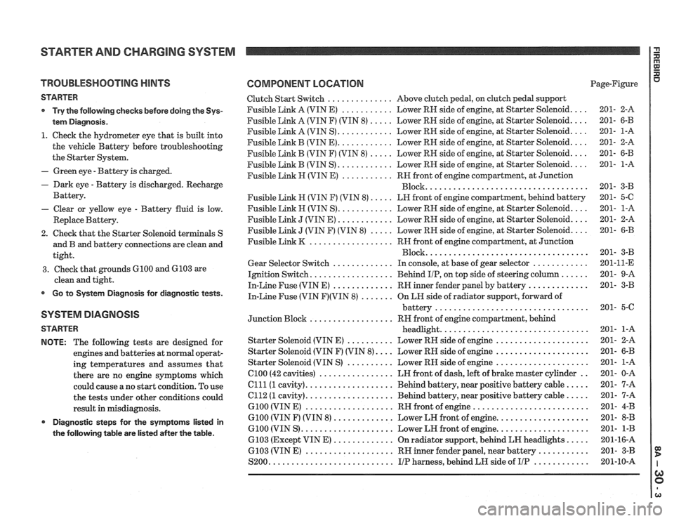
COMPONENT LOCATION Page-Figure
Clutch Start Switch
.............. Above clutch pedal. on clutch pedal support
Fusible Link A (VIN E)
........... Lower RH side of engine. at Starter Solenoid .... 201- 2-A
Fusible Link A (VIN F) (VIN
8) ..... Lower RH side of engine. at Starter Solenoid .... 201- 6-B
Fusible Link A (VIN S)
............ Lower RH side of engine. at Starter Solenoid .... 201- 1-A
Fusible Link B (VIN
E) ............ Lower RH side of engine. at Starter Solenoid .... 201- 2-A
Fusible Link
B (VIN F) (VIN 8) ..... Lower RH side of engine. at Starter Solenoid .... 201- 6-B
Fusible Link B (VIN S)
............ Lower RH side of engine. at Starter Solenoid .... 201- 1-A
Fusible Link
H (VIN E) ........... RN front of engine compartment. at Junction
................................... Block 201- 3-B
Fusible Link
H (VIN F) (VIN 8) ..... LH front of engine compartment. behind battery 201- 5-C
Fusible
Link H (VIN S) ............ Lower RH side of engine. at Starter Solenoid .... 201- 1-A
Fusible Link
J (VIN E) ............ Lower RH side of engine. at Starter Solenoid .... 201- 2-A
Fusible Link
J (VIN F) (VIN 8) ..... Lower RH side of engine. at Starter Solenoid .... 201- 6-B
Fusible Link
K .................. RH front of engine compartment. at Junction
................................... Block 201- 3-B
Gear Selector Switch
............. In console. at base of gear selector ............ 201-11-E
Ignition Switch
.................. Behind IIP. on top side of steering column ...... 201- 9-A
In-Line Fuse (VIN E)
............. RH inner fender panel by battery ............. 201- 3-B
In-Line Fuse (VIN F)(VIN 8) ....... On LN side of radiator support. forward of
battery
................................. 201- 5-C
Junction Block
.................. RH front of engine compartment. behind
headlight
................................ 201- 1-A
Starter Solenoid (VIN
E) .......... Lower RH side of engine .................... 201- 2-A
Starter Solenoid (VIN F) (VIN
8) .... Lower RH side of engine .................... 201- 6-B
Starter Solenoid (VIN S)
.......... Lower RH side of engine .................... 201- 1-A
el00 (42 cavities) ................ LH front of dash. left of brake master cylinder .. 201- 0-A
Clll(1 cavity) ................... Behind battery. near positive battery cable ..... 201- 7-A
el12 (1 cavity) ................... Behind battery. near positive battery cable ..... 201- 7-A
G100 (VIN E) ................... RH front of engine ......................... 201- 4-B
G100 (VIN F) (VIN 8) ............. Lower LH front of engine .................... 201- 8-B
6100 (VIN S) .................... Lower LH front of engine .................... 201- 1-B
6103 (Except VIN
E) ............. On radiator support. behind LH headlights ..... 201-16-A
6103 (VIN
E) ................... RH inner fender panel. near battery ........... 201- 3-B
S200
........................... IIP harness. behind LH side of IIP ............ 201-10-A
Page 1298 of 1825
STARTER AND CHARGING SYSTEM
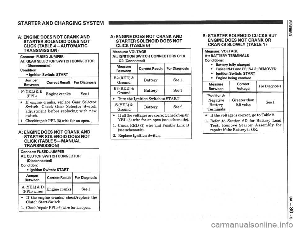
A: ENGINE DOES NOT CRANK AND
STARTER SOLENOID DOES NOT
CLICK (TABLE 4-AUTOMATIC
TRANSMISSION)
Connect: FUSED JUMPER
At: GEAR SELECTOR SWITCH CONNECTOR
(Disconnected)
Condition:
0 Ignition Switch: START
I
Jumper I Corren Resuk I For Diagnosis I Between
I (:::LI& IEngine cranks I See 1 1
If engine cranks, replace Gear Selector
Switch. Check Gear Selector Switch
adjustment before replacing with new
switch.
1. ChecWrepair PPL (6) wire for an open.
A: ENGINE DOES NOT CRANK AND
STARTER SOLENOlD DOES NOT
CLICK (TABLE 5-MANUAL
TRANSMISSION)
Connect: FUSED JUMPER
At: CLUTCH SWITCH CONNECTOR
(Disconnected)
Condition:
I 0 lanition Switch: START I
I :if,",":: 1 Engine cranks I See 1 I
Jumper
Between
If the engine cranks, checklreplace the
Clutch Start Switch.
1. Checklrepair PPL (6) wire for an open.
A: ENGINE DOES NOT CRANK AND B:
STARTER SOLENOID CLICKS BUT
STARTER
SOLENOID DOES NOT ENGINE DOES NOT CRANK OR
CLICK (TABLE 61 CRANKS SLOWLY (TABLE 1)
Correct Result Measure:
VOLTAGE
At: IGNITION SWITCH CONNECTORS
C1 &
C2 (Connected)
For Diagnosis
I Measure ( Correct Result I For Diagnosis 1 Between
I B2 (RED)& I Battery ( See 1 I Ground
I B3 IRED'& I Battery ( See 1 1 Ground
0 Turn the Ignition Switch to START
Measure: VOLTAGE
At: BPirTERV TERMINALS
Conditions: Battery fully charged
0 Fuses lNJ1 and FPIINJ 2: REMOVED
Ignition Switch: START
Engine being cranked
See 2 IYEL' &
Ground
For Diagnosis
See
Measure
Between
Positive &
Negative Battery
Terminals
If
all the voltages are correct, checklrepair
YEL (5) wire for an open (see schematic).
1. Check RED (2) wire and Fusible Link B
(see schematic).
2. Replace Ignition Switch.
Battery
0 If
the voltage is correct, go to Table 2.
1. Refer to Section 6D for Battery Load
Test. Remove Starter Assembly for
repairs if the Battery is
OK.
Correct
Voltage
Greater than
9.5 volts
Page 1303 of 1825
STARTER AND CHARGING SYSTEM
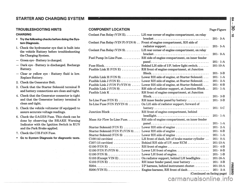
TROUBLESHOOTING HINTS
CHARGING
* Try the following checks before doing the Sys-
tem Diagnosis
.
1 . Check the hydrometer eye that is built into
the vehicle Battery before troubleshooting
the Charging System
.
- Green eye . Battery is charged .
. Dark eye . Battery is discharged . Recharge
Battery
.
- Clear or yellow eye . Battery fluid is low .
Replace Battery .
2 . Check the Generator Belt .
3 . Check that the Starter Solenoid terminal B
and battery connections are clean and tight
.
4 . Check that the Generator connector is tight
and that the Generator battery terminal is
clean and tight
.
5 . Check the vehicle voltmeter (if equipped) to
assure accurate voltage readings
.
6 . Check the GAGES Fuse . This check can be
done by observing the BRAKE Warning
Indicator with the Ignition Switch in RUN
and the Park Brake applied
.
7 . Check the GIN-FAN Fuse .
Go to System Diagnosis for diagnostic tests .
COMPONENT LOCATION Page-Figure
Coolant Fan Relay (VIN
E) ......... LH rear corner of engine compartment. on relay
bracket
................................. 201- 3-A
Coolant Fan Relay (VIN F) (VIN 8)
. . Front of engine compartment. RH side of
radiator support
.......................... 201- 5-A
Coolant Fan Relay (VIN S)
......... LN rear corner of engine compartment. on relay
bracket
................................. 201- 0-A
Fuel Pump In-Line Fuse
........... RH side of engine compartment. on inner fender
panel
................................... 201- 1-A
Fuse Block
...................... Behind LN side of IIP. below light switch ....... 201-10-A
Fusible Link H (VIN E)
........... RH front of engine compartment. at Junction
................................... Block 201- 3-B
Fusible Link
H (VIN S) ............ Lower RN side of engine. at Starter Solenoid .... 201- 1-A
Fusible Link
J (VIN E) ............ Lower RH side of engine. at Starter Solenoid .... 201- 2-A
Fusible Link
J (VIN F) (VIN 8) ..... Lower RH side of engine. at Starter Solenoid .... 201- 6-B
Fusible Link
J (VIN S) ............ RH side of radiator support. at Junction Block .. 201- 1-A
Fusible Link
K .................. RH front of engine compartment. at Junction
................................... Block 201- 3-B
In-Line Fuse (VIN E)
............. RH inner fender panel by battery ............. 201- 3-B
In-Line Fuse (VIN
F)(VIN 8) ....... On LH side of radiator support. forward of
................................. battery 201- 5-6
.................. Junction Block RH
front of engine compartment. behind
................................ headlight 201- 1-A
........ Mass Air Flow In-Line Fuse RR side of engine compartment. on inner fender
................................... panel 201- 1-A
Starter Solenoid (VIN E)
.......... Lower RH side of engine .................... 201- 2-A
Starter Solenoid (VIN F) (VIN
8) .... Lower RH side of engine .................... 201- 6-B
Starter Solenoid (VIN S)
.......... Lower RN side of engine .................... 201- 1-A
el00 (42 cavities) ................ LH front of dash. left of brake master cylinder .. 201- 0-A
C207 (15 cavities)
................ Behind RH side of IIP. near ECM ............. 201-13-A
G100 (VIN E) ................... RH front of engine ......................... 201- 4-B
G100 (VIN F) (VIN 8) ............. Lower LH front of engine .................... 201- 8-B
G100 (VIN S) .................... Lower LH front of engine .................... 201- 1-B
6103 (Except VIN E) ............. On radiator support. behind LH headlights ..... 201-16-A
6.103 (VIN E) ................... RH inner fender panel. near battery ........... 201- 3-B
S204
........................... IIP harness. behind instrument cluster ......... 201-10-A
S206 (VIN
E) .................... Engine harness. RH front of dash ............. 201- 2-A
(Continued on facing page)
Page 1304 of 1825
STARTER AND CHARGING SYSTEM
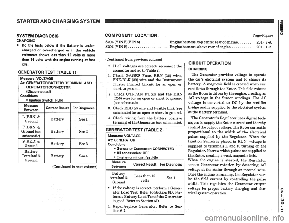
SYSTEM DIAGNOSIS
CHARGING Do the tests below if the Battery is under-
charged or overcharged or if the vehicle
voltmeter shows less than
12 volts or more
than
16 volts with the engine running at fast
idle.
GENERATOR TEST (TABLE 1)
GENERATOR CONNECTOR
(Continued in next column)
COMPONENT LOCATION Page-Figure
...... S206 (VIN F)(VIN 8). ............. Engine harness, top center rear of engine.
201- 7-A
.......... S206 (VIN S) .................... Engine harness, above rear of engine
201- 1-A
(Continued from previous column)
If
all voltages are correct, reconnect the
connector and go to Table 2.
1. Check GAGES Fuse, BRN (25) wire,
PNKIBLK (39) wire and the Instrument
Cluster Printed Circuit for an open or
short to ground.
2. Check
CIH-FAN FUSE and the BRN
(250) wire for an open or short to ground
(see schematic).
3. Check RED (2) wire and Fusible Link (see
schematic) for an open or short to ground.
4. Check wiring from the battery positive
terminal of the Generator (see schematic).
GENERATOR TEST (TABLE 2)
Measure: VOLTAGE
At: GENERATOR
Conditions: Generator Connector: CONNECTED
All accessories: OFF
Engine running at fast idle
Measure I Correct Resuk I For Diagnosis / 1 Between
Battery
terminal
& Less than 16
1 Ground 1 1 See 1
If the voltage is correct, perform a Gener-
ator Load Test. Refer to Section 6D. Per-
form a Battery Load Test if the Generator
is good. Refer to Section 6D.
1. Repairlreplace Generator. Refer to Sec-
tion 6D.
CIRCUIT OPERATION
CHARGING
The Generator provides voltage to operate
the car's electrical system and to charge its
battery. A magnetic field is created when cur-
rent flows through the Rotor. This field rotates
as the Rotor is driven by the engine, creating an
AC voltage in the Stator windings. The AC
voltage is converted to DC by the rectifier
bridge and is supplied to the electrical system
at the Battery ter
The Generator's Regulator uses digital tech-
niques to supply the Rotor current and thereby
control the output voltage. The Rotor current is
proportional to the width of the electrical
pulses supplied by the Regulator. When the
Ignition Switch is placed in RUN, voltage is
supplied to terminals L and F, turning on the
Regulator. Narrow width pulses are supplied to
the Rotor, creating a weak magnetic field.
When the engine is started, the Regulator
senses Generator rotation by detecting
AC
voltage at the stator through an internal wire.
Once the engine is running, the Regulator var-
ies the field current by controlling the pulse
width. This regulates the Generator output
voltage for proper battery charging and elec-
trical system operation.
Page 1309 of 1825
COOLANT FAN I g
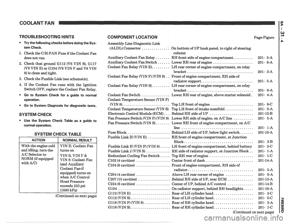
TROUBLESHOOTING HINTS
@ Try the following checks before doing the Sys-
tem Check.
1. Check the CIH-FAN Fuse if the Coolant Fan
does not run.
2. Check that ground 6112 (V6 VIN S), 6117
(V8 VIN E) or 6104 (V8 VIN F and V8 VIN
8) is clean and tight.
3. Check the Fusible Link (see schematic).
4.
If the Coolant Fan runs with the Ignition
Switch OFF, replace the Coolant Fan Relay.
@ Go to System Check for a guide to normal
operation.
Go to System Diagnosis for diagnostic tests.
SYSTEM CHECK
Use the System Checlc Table as a guide to
normal operation.
SYSTEM CHECK TABLE
I ACTION I NORMALRESULT 1
COMPONENT LOCATION Page-Figure
Assembly Line Diagnostic Link
(ALDL) Connector .............. On bottom of IIP hush panel, to right of steering
column
Auxiliary Coolant Fan Relay
....... RH front side of engine compartment. ......... 201- 5-A
Auxiliary Coolant Fan Switch
...... Lower RN rear of engine .................... 201- 6-A
Coolant Fan Relay (VIN
E). ........ LH rear corner of engine compartment, on relay
bracket
................................. 201- 3-A
Coolant Fan Relay (VIN F) (VIN 8)
. . Front of engine compartment, RN side of
radiator support.
......................... 201- 5-A
Coolant Fan Relay (VIN S)
......... LH rear corner of engine compartment, on relay
................................. bracket 201- 0-A
Coolant Fan Switch
.............. Lower RH rear of engine, above starter solenoid . 201- 4-A
Coolant Temperature Sensor (VIN F)
(VIN 8).
....................... Top LW front of engine. ..................... 201- 8-C
Coolant Temperature Sensor (VIN S) Top LH front of intake manifold.
............. 201- 0-A
Electronic Control Module (ECM)
... Behind RN side of IIP ...................... 201-12-B
Fan Pressure Switch (VIN F) (VIN 8) Lower RH side of engine, on
AIC line .......... 201- 5-A
Fan Pressure Switch (VIN S)
....... Lower RN front of engine compartment, on AIC
line .................................... 201- 1-A
Fuse Block.
..................... Behind LN side of IIP, below light switch. ...... 201-10-A
Fusible Link
N (VIN E) ........... RH front of engine compartment, at Junction
Block ................................... 201- 3-B
Fusible Link N (VIN F) (VIN 8).
.... LN front of engine compartment, behind battery 201- 5-C
Fusible Link
J (VIN S) ............ RN side of radiator support, at Junction Block .. 201- 1-A
Redundant Cooling Fan Switch.
.... Top RW rear of engine ...................... 201- 1-6
C102 (4 cavities) ................. Center front of dash. ....................... 201-14-A
6104 (6 cavities)
................. Front of engine compartment, RH side of
................................ radiator. 201- 5-A
C204 (4 cavities) ................. Above LH rear corner of engine .............. 201- 0-A
C207 (15 cavities)
................ Behind RH side of IIP, near ECM ............. ,201-13-A
C224 (6 cavities) ................. Center of IIP, behind AIC control ............. 201-14-B
6104
.......................... On radiator support, behind RN headlights. .... 201-16-A
6112 (VIN E)
................... Rear of LN cylinder head. ................... 201- 3-C
6112 (VIN S)
.................... Rear of LH cylinder head. ................... 201- 0-C
6118 (VIN F) (VIN 8)
............. Rear of RH cylinder head. ................... 201- 5-A
6118 (VIN S)
.................... Rear of RH cylinder head. ................... 201- 1-C
(Continued on next page)
With
the engine cold
and idling, turn the
AIC Selector to
NORM (if equipped
with Ale)
VIN E: Coolant Fan
turns on
VIN S, VIN
F &
VIN 8: Coolant Fan
(and Auxiliary
Coolant Fan-if
equipped) turns on
when
A/C Control
Head Pressure
exceeds 233 psi
(1600
kPa)
(Continued on next page)
Page 1312 of 1825
COOLANT FAN rn
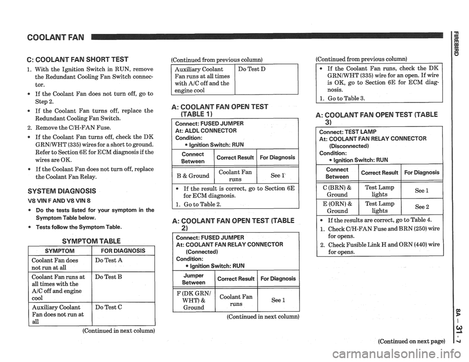
6: COOLANT FAN SHORT TEST
1. With the Ignition Switch in RUN, remove
the Redundant Cooling Fan Switch connec-
tor.
If the Coolant Fan does not turn off, go to
Step
2.
If the Coolant Fan turns off, replace the
Redundant Cooling Fan Switch.
2. Remove the CIR-FAN Fuse.
If the Coolant Fan turns off, check the DK
GRNIWHT
(335) wires for a short to ground.
Refer to Section 6E for ECM diagnosis if the
wires are OK.
a If the Coolant Fan does not turn off, replace
the Coolant Fan Relay.
SYSTEM DlAGNOSlS
V8 VIN F AND V8 VIN 8
Do the tests listed for your symptom in the
Symptom Table below.
Tests follow the Symptom Table.
SYMPTOM TABLE
I SYMPTOM I FORDIAGNOSIS I
I Do Test A I
I not run at aB I I
Coolant Fan runs at
all times with the
A/C off and engine
cool
(Continued in next column)
Do
Test
B
Auxiliary Coolant
Fan does not run at
all
:Continued from previous column)
Fan runs at
all times
with
AIC off and the
Do Test C (Continued
from previous column)
GRNIWNT
(335) wire for an open. If wire
is OK, go to Section 6E for ECM diag-
nosis.
1. Go to Table 3.
A: COOLANT FAN OPEN TEST
(TABLE
1)
At: ALDL CONNECTOR
Condition:
I B &Ground I I See l' I
Connect
Between
If the result is correct, go to Section 6E
for ECM diagnosis.
A: COOLANT FAN OPEN TEST (TABLE
2)
Correct Result
I
Connect: FUSED JUMPER
At: COOLANT FAN RELAY CONNECTOR For
Diagnosis
(Connected)
Condition: lgnition Switch: RUN
Jumper
I Correct Result I For Diagnosis I Between
(DK GRN1 Coolant Fan
WHT) & See 1
1 Ground 1 runs 1 1
A: COOLANT FAN OPEN TEST (TABLE
3) I
Connect: TEST LAMP
At: COOLANT FAN RELAY CONNECTOR
(Disconnected)
Condition:
Connect I Correct Rewn I For Diagnosis I I Between
C (BRN) &
Ground
If the results are correct, go to Table
4.
1. Check CIH-FAN Fuse and BRN (250) wire
for opens.
2. Check Fusible Link H and ORN (440) wire
for opens.
E (ORN)
&
Ground
(Continued in next column)
(Continued on next page)
Test Lamp
lights See
1
Test
Lamp
lights See 2
Page 1318 of 1825
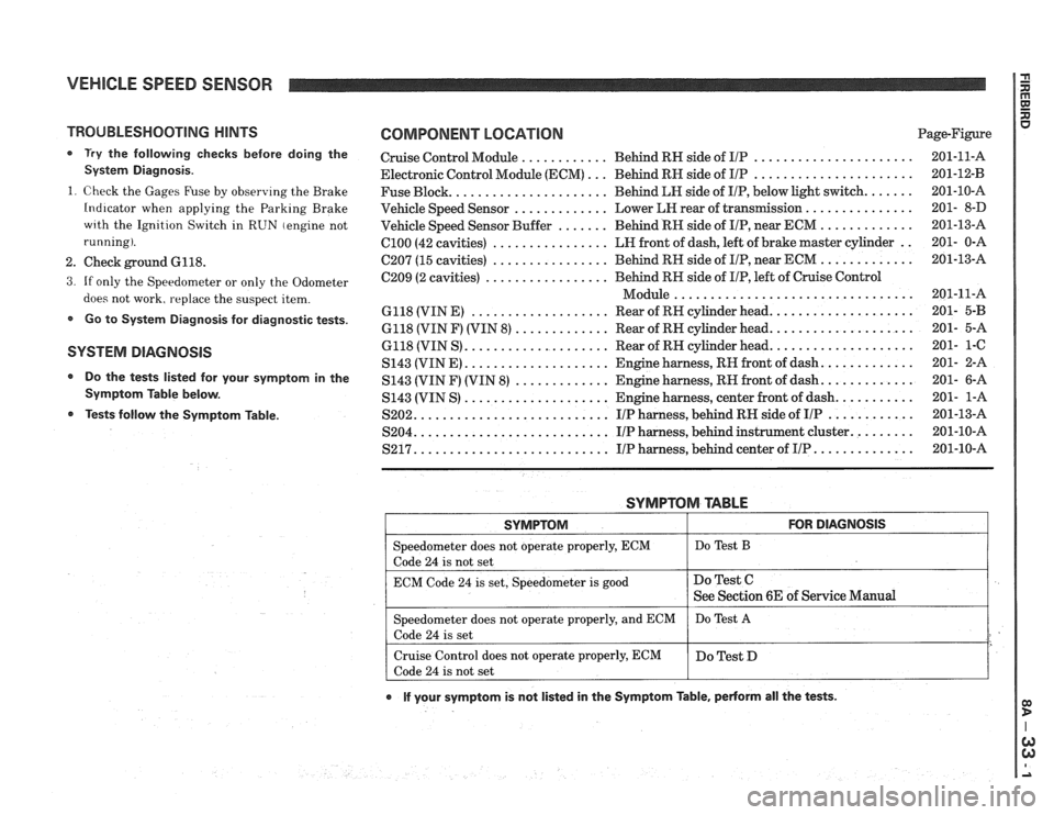
VEHICLE SPEED SENSOR
TROUBLESHOOTING HINTS
0 Try the following checks before doing the
System Diagnosis
.
1
. Check the Gages Fuse by observing the Brake
Indicator when applying the Parking Brake
wrth the Ignition Switch in RUN (engine not
running)
.
2 . Check ground 6118 .
3 . If only the Speedometer or only the Odometer
does not work. replace the suspect item
.
Go to System Diagnosis for diagnostic tests .
SYSTEM DlAGNOSlS
Do the tests listed for your symptom in the
Symptom Table below
.
Tests follow the Syrnptom Table .
COMPONENT LOCATION Page-Figure
Cruise Control Module
............ Behind RN side of IlP ...................... 201-11-A
Electronic Control Module (ECM)
... Behind RN side of IIP ...................... 201-12-B
Fuse Block
...................... Behind LN side of IIP. below light switch ....... 201-10-A
Vehicle Speed Sensor
............. Lower LEI rear of transmission ............... 201- 8-D
Vehicle Speed Sensor Buffer
....... Behind RH side of IIP. near ECM ............. 201-13-A
ClOO (42 cavities) ................ LN front of dash. left of brake master cylinder .. 201- 0-A
C207 (15 cavities) ................ Behind RH side of IIP. near ECM ............. 201-13-A
C209 (2 cavities)
................. Behind RN side of IIP. left of Cruise Control
................................. Module 201-11-A
6118 (VIN E)
................... Rear of RH cylinder head .................... 201- 5-B
6118 (VIN F) (VIN 8) ............. Rear of RN cylinder head .................... 201- 5-A
6118 (VIN S)
.................... Rear of RN cylinder head .................... 201- 1-C
S143 (VINE)
.................... Engine harness. RH front of dash ............. 201- 2-A
S143 (VIN F) (VIN
8) ............. Engine harness. RN front of dash ............. 201- 6-A
S143 (VIN S)
.................... Engine harness. center front of dash ........... 201- 1-A
S202
........................... IIP harness. behind RH side of IIP ............ 201-13-A
S204
........................... IIP harness. behind instrument cluster ......... 201-10-A
S217 ........................... IIP harness. behind center of IIP .............. 201-10-A
SYMPTOM TABLE
I SYMPTOM I FOR DIAGNOSIS I
=liter does not operate properly. ECM I Do Test B
code 24 is not set
ECM Code
24 is set. Speedometer is good
e If your symptom is not listed in the Symptom Table. pedorm all the tests .
Do Test C
See Section 6E of Service Manual
Speedometer does not operate properly. and ECM
Code
24 is set
Cruise Control does not operate properly. ECM
Code
24 is not set Do
Test
A
Do Test D
Page 1323 of 1825
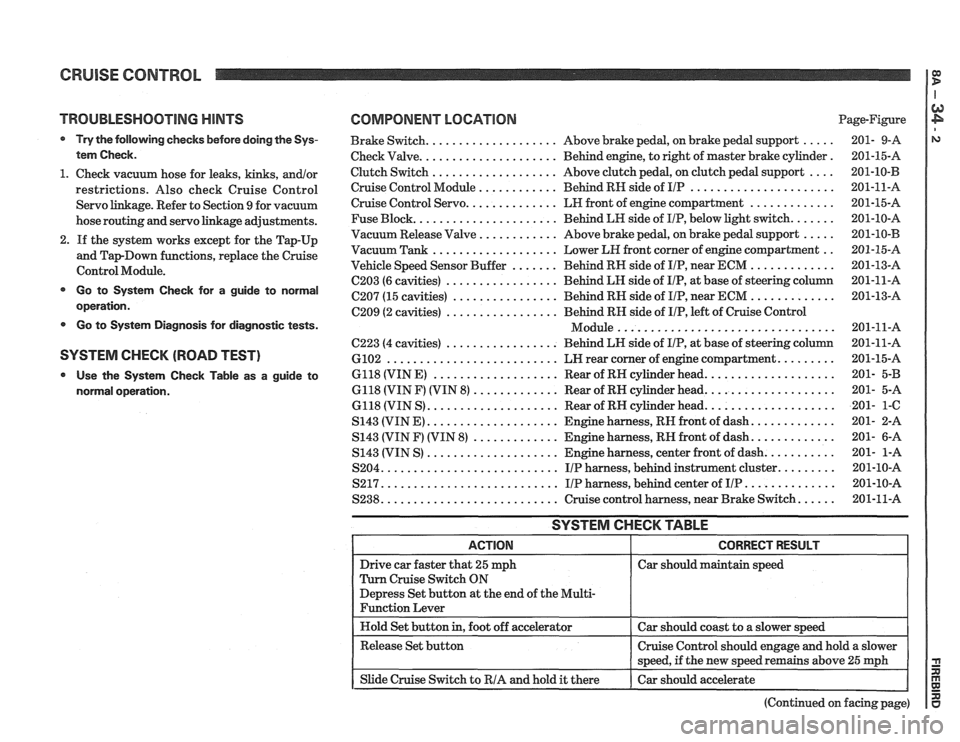
CRUISE CONTROL
TROUBLESHOOTING HINTS
Try the following checks before doing the Sys-
tem Check
.
1 . Check vacuum hose for leaks. kinks. andlor
restrictions . Also check Cruise Control
Servo linkage
. Refer to Section 9 for vacuum
hose routing and servo linkage adjustments
.
2 . If the system works except for the Tap-Up
and
TapDown functions. replace the Cruise
Control Module
.
Go to System Check for a guide to normal
operation
.
Go to System Diagnosis for diagnostic tests .
SYSTEM CHECK (ROAD TEST)
Use the System Check Table as a guide to
normal operation
.
COMPONENT LOCATION Page-Figure
Brake Switch
.................... Above brake pedal. on brake pedal support ..... 201- 9-A
Check Valve
..................... Behind engine. to right of master brake cylinder . 201-15-A
Clutch Switch
................... Above clutch pedal. on clutch pedal support .... 201-10-B
Cruise Control Module
............ Behind RH side of IIP ...................... 201-11-A
Cruise Control Servo .............. LH front of engine compartment ............. 201-15-A
Fuse Block
...................... Behind LH side of IIP. below light switch ....... 201-10-A
Vacuum Release Valve
............ Above brake pedal. on brake pedal support ..... 201-10-B
Vacuum Tank ................... Lower LH front corner of engine compartment .. 201-15-A
Vehicle Speed Sensor Buffer
....... Behind RH side of IIP. near ECM ............. 201-13-A
C203 (6 cavities) ................. Behind LH side of IIP. at base of steering column 201-11-A
C207 (15 cavities) ................ Behind RH side of IIP. near ECM ............. 201-13-A
C209 (2 cavities) ................. Behind RH side of IIP. left of Cruise Control
................................. Module 201-11-A
C223 (4 cavities) ................. Behind LH side of IIP. at base of steering column 201-11-A
6102 .......................... LN rear corner of engine compartment ......... 201-15-A
6118 (VIN E)
................... Rear of RH cylinder head .................... 201- 5-B
6118 (VIN F) (VIN 8)
............. Rear of RN cylinder head .................... 201- 5-A
6118 (VIN S)
.................... Rear of RN cylinder head .................... 201- 1-C
S143 (VIN E) .................... Engine harness. RH front of dash ............. 201- 2-A
S143 (VIN
F) (VIN 8) ............. Engine harness. RN front of dash ............. 201- 6-A
S143 (VIN S)
.................... Engine harness. center front of dash ........... 201- 1-A
S204
........................... IIP harness. behind instrument cluster ......... 201-10-A
S217
........................... IIP harness. behind center of IIP .............. 201-10-A
S238
........................... Cruise control harness. near Brake Switch ...... 201-11-A
SYSTEM CHECK TABLE
Car should maintain speed
(Continued on facing page)