height adjustment PONTIAC FIERO 1988 Service Repair Manual
[x] Cancel search | Manufacturer: PONTIAC, Model Year: 1988, Model line: FIERO, Model: PONTIAC FIERO 1988Pages: 1825, PDF Size: 99.44 MB
Page 109 of 1825
26-2 CHASSIS SHEET METAL
TO RAISE OR LOWER THE FRONT comers
for proper alignment, proceed as follows:
1. Close hood firmly.
2. Determine the amount of adjustment necessary.
3. Open hood.
4. Raise or lower the adjustable hood bumpers as
required.
FORE AND APT adjustment can be accom-
plished as follows:
1. Loosen hinge to fender attaching screws.
Remove or Disconnect
Open hood.
Scribe line on hood inner panel and fender panel
to indicate original hinge position.
Block hood on side where hinge is to be
removed.
Prop hood open.
Remove hinge-to-hood attaching screws and
hinge-to-fender attaching screws.
Carefully remove hinge and strut assembly.
- -
2. Reposition hinge assembly. install or Conned 3. Tighten hinge to fender attaching screws to
specifications. 1. Mount new hinge on fender using scribed line
4. If necessary, repeat procedure on opposite side for location,
and tighten attaching screws.
of hood. 2.
Position hinge to hood using scribed line for
location, install attaching screws and tighten.
3. Carefully close hood and check for proper
- - alignment.
4. If hood is misaligned, measure amount of
mis-
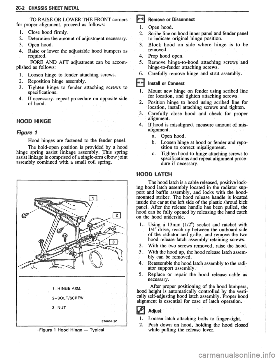
Figure 7
Hood hinges are fastened to the fender panel.
The hold-open position is provided by a hood
hinge spring assist linkage assembly. This spring
assist linkage is comprised of a
single-am elbow joint
assembly combined with a small coil spring.
1-HINGE ASM.
2-BOLT/SCREW
Figure 1 Hood Hinge - Typical
alignment.
a. Open hood.
b. Loosen hinge at hood or fender and repo-
sition to correct misalignment.
c. Tighten hood-to-hinge attaching screws to
specifications and repeat alignment proce-
dure if necessary.
HOOD L14TCI-I
The hood latch is a cable released, positive lock-
ing hood latch assembly located in the radiator sup-
port and baffle assembly, and locks with the
hood-
mounted striker. The hood release handle is located
inside the car at the left side of the plastic shroud kick
panel. After the release handle has been pulled, the
hood can be fully opened by releasing the hand catch
on the hood underside.
1. Using a
13mrn (112") socket and ratchet with
114" drive, reach up between the outboard side
of the radiator and grille, and remove the two
hood release latch assembly retaining screws.
2. With the two screws removed, raise the hood.
3. With the hood up, the hood release latch assem-
bly can be removed.
4. Reassemble the hood latch assembly to the radi-
ator support assembly.
5. Replace or repair the hood release cable as
necessary.
After proper positioning of the hood bumpers,
hood height is automatically controlled by the verti-
cally self-adjusting hood latch assembly. Proper hood
alignment is essential for ease of latch operation.
Adjust
1. Loosen latch attaching bolts to finger-tight.
2. Push down on hood, holding the hood closed
while pulling the release lever.
Page 127 of 1825
3-2 STEERING, SUSPENSION, TIRES AND WHEELS DIAGNOSIS
o Excessive wheel runout
e Blister or bump on tire
e Excessive loaded radial runout of tire and wheel
assembly
Hard Steering (Power)
lnspect
e Hydraulic system - Make test with gage J 5176
or J 25323
e Steering gear adjustment
e Bind or catch in steering gear
e Loose steering gear mounting
e Steering gear pressure port check valve (800
series)
Too Much Play In Steering
a lnspect
e Wheel bearings worn
e Loose steering gear mounting
e Joints from column to steering gear loose or worn
e Steering gear adjustment
Poor Returnability (Power)
Inspect
e Lack of lubrication - ball joints and tie rod ends
o Bind in ball joints
o Rind in steering column
e Front-wheel alignment
e Steering gear adjustment
e Sticking valve
o Steering gear adjustment
e Lower coupling binding on steering gear
Abnormal Noise, Front End
lnspect
Lubrication - ball joints and tie rod ends
Damaged suspension components
Worn control arm bushings or tie rod ends
Imose stabilizer shaft
Loose wheel nuts
Loose suspension bolts
Wheel covers
Steering gear adjustment
Worn strut dampener, shock absorbers or
n~ountings
Spring improperly positioned
Wander or Poor Steering Stability
Inspect
o Mismatched or uneven tires
e Lubrication - ball joints and tie rod ends
e Worn strut dampeners or shock absorbers
e Loose stabilizer shaft Broken
or sagging springs
e Steering gear adjustment
e Front-wheel or rear-wheel alignment
Erratic Steering When Braking
lnspect
e Wheel bearings worn
e Broken or sagging springs
e Leaking wheel cylinder or caliper
Warped rotors
e Incorrect or uneven caster
Low Or Uneven Trim Height
e Broken or sagging springs
@ Overloaded car
e Incorrect or weak springs
Ride Too Soft
Inspect
e Worn strut dampeners or shock absorbers
e Incorrect or sagging springs
Ride Too Harsh
lnspect -
e Incorrect strut dampeners or shock absorbers
e Incorrect springs
Body Leans Or Sways In Corners
lnspect
e Loose stabilizer shaft
e Worn strut dampeners, shock absorbers or
mounting
a Broken or sagging springs
e Overloaded car
Suspension Bottoms
lnspect
a Overloaded car
e Worn strut dampeners or shock absorbers
e Incorrect, broken or sagging spring
"Dog" Tracking
lnspect
e Damaged rear suspension arm or worn bushings
e Bent rear axle
e Frame or underbody alignment incorrect
Page 139 of 1825
3-14 STEERING, SUSPENSION, TIRES AND WHEELS DIAGNOSIS
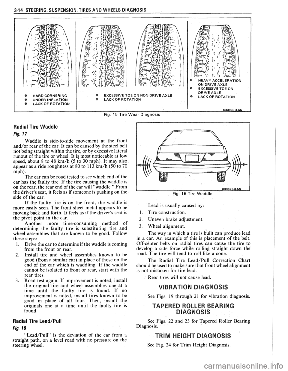
@ HARD CORNERING O UNDER INFLATION LACK OF ROTATION
@ HEAVY ACCELERATION ON DRIVE AXLE EXCESSIVE TOE ON DRIVE AXLE EXCESSIVE TOE ON NON-DRIVE AXLE @ LACK OF ROTATION O LACK. OF ROTAT ION
Fig. 15 Tire Wear Diagnosis
Radial Tire Waddle
Fig. 17
Waddle is side-to-side movement at the front
and/or rear of the car. It can be caused by the steel belt
not being straight within the tire, or by excessive lateral
runout of the tire or wheel. It ig most noticeable at low
speed, about 8 to 48
km/h (5 to 30 mph). It may also
appear as a ride roughness at 80 to 113
km/h (50 to 70
mph). The car can be road tested to see which end of the
car has the faulty tire. If the tire causing the waddle is
on the rear, the rear end of the car will "waddle." From
the driver's seat, it feels as if someone is pushing on the
side of the car.
If the faulty tire is on the front, the waddle is
more easily seen. The front sheet metal appears to be
moving back and forth. It feels as if the driver's seat is
the pivot point in the car.
Another more time-consuming method of
determining the faulty tire is substituting tire and
wheel assemblies that are known to be good. Follow
these steps:
1. Drive the car to determine if the waddle is coming
from the front or rear.
2. Install tire and wheel assemblies known to be
good (from a similar car) in place of those on the
end of the car which is waddling. If the waddle
cannot be isolated to front or rear, start with the
rear tires.
3. Road test again. If improvement is noted, install
the original tire and wheel assemblies one at a
time until the faulty tire is found. If no
improvement is noted, install tires known to be
good in place of all four. Then, install the
originals one at a time until the faulty tire is
found.
Radial Tire Lead/Pull
Fig. 18
"Lead/Pull" is the deviation of the car from a
straight path, on a level road with no pressure
on the
steering wheel.
L Fig. 16 Tire Waddle
Lead is usually caused by:
1. Tire construction.
2. Uneven brake adjustment.
3. Wheel alignment.
The way in which a tire is built can produce lead
in a car. An example of this is placement of the belt.
Off-center belts on radial tires can cause the tire to
develop a side force while rolling straight down the
road. The tire will tend to roll like a cone.
The Radial Tire
Lead/Pull Correction Chart
should be used to make sure that front wheel alignment
is not mistaken for tire lead.
Rear tires will not cause lead.
VIBRATION DIAGNOSIS
See Figs. 19 through 21 for vibration diagnosis.
TAPERED ROLLER BEARING
DlAGNOSlS
See Figs. 22 and 23 for Tapered Roller Bearing
Diagnosis.
See Fig. 24 for Trim Height Diagnosis.
Page 148 of 1825
-
WHEEL. ALIGNMENT 3A-1
SECTION 3A
WHEEL AL GNMENT
NOTICE: These fasteners are important attaching Do not use a replacement part of lesser quality or
parts, in that they could affect the performance of substitute
design. Torque values must be used as
vital components and systems, and/or could result specified during reassembly to assure proper
in major repair expense. They must be replaced retention of these parts. For prevailing torque
with one of the same part number or with an
nut(s) and bolt(s), refer to the "Reuse of Prevailing
equivalent part if replacement becomes necessary. torque
Nut(s) and Bolt(s)" chart in Section 0.
General Description ...................... .. ...... 3A- 1 On-Car Service ........................ .. ........... 3A-2
Caster .................... .. ............................ 3A- 1 Caster and Camber Adjustment .................. 3A-2
..................................... Camber ................... .. .............................. 3A-I Toe-In Adjustment 3A-2
Toe.. ................................................. 3A- 1 Axle Housing Alignment ......................... .... 3A-4
Preliminary Checks Prior to Specifications ....................... ... ............... 3A-4
Adjusting Alignment ..................... ...... 3A- 1
GENERAL DESCRIPmIOMI
Wheel alignment refers to the angular they tend to roll parallel on the road when the car is
relationship between the wheels, the suspension moving.
attaching parts and the ground.
PRELIMINARY CHECKS PRIOR TO ADJUSTING
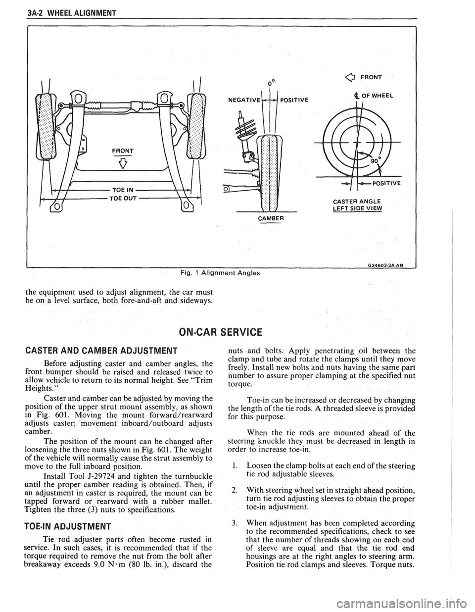
CASTER ALIGNMENT
Figure 1
Caster is the amount the top of the strut is tilted
forward or rearward from the vertical. When the strut
tilts rearward, the center is "positive"
(+). The
amount of tilt is measured in degrees from vertical.
CAMBER
Figure 1
Camber is the tilting of the wheels from the
vertical when viewed from the front of the car. When
the wheels tilt outward at the top, the camber is said
to be positive
(+). When the wheels tilt inward at the
top, the camber is said to be negative
(-). The amount
of tilt is measured in degrees from the vertical and this
measurement is called the camber angle.
TOE
Figure i
Toe is a measurement of how much the front of
the wheels are turned in or out from a straight-ahead
position. When the wheels are turned in, toe is
"positive"
(+). When the wheels are turned out, toe
is "negative"
(-). The actual amount of toe-in is
normally only a fraction of a degree. The purpose of a
toe specification is to ensure parallel rolling of the
wheels (excessive toe-in or toe-out may increase tire
wear). Toe also serves to offset the small deflections of
the wheel support system which occur when the car is
rolling forward. In other words, even when the wheels
are set to toe-in slightly when the car is standing still, Steering
and vibration complaints are not always
the result of improper alignment. Another possibility
is tire "lead" due to worn or improperly manufactured
tires. "Lead" is the deviation of the car from a straight
path on a level road without hand pressure on the
steering wheel. Section
3 of this manual contains a
procedure for determining the presence of a tire lead
problem.
Before making any adjustment affecting wheel
alignment, make the following checks to ensure correct
alignment readings and alignment adjustments:
1. Check all tires for proper inflation pressures and
approximately the same tread wear.
2. Hub and bearing assemblies for excessive wear;
correct if necessary.
3. Ball joints and tie rod ends; if they are excessively
lcose, correct them before adjusting.
4. Run-out of wheels and tires.
5. Car trim height; if out of limits and a correction
is to be made, do so before adjusting alignment.
Refer to Section
3 for trim height specifications.
6. Strut dampeners for proper operation.
7. Control arms for loose bushings.
8. Loose or missing stabilizer bar attachments.
Consideration must be given to excess loads, such
as tool boxes, sample cases, etc. If these items are
normally carried in the car, they should remain in the
car during alignment adjustments. Consideration
should also be given to the condition of the equipment
used to adjust alignment. Be sure to follow the
equipment manufacturer's instructions. Regardless
of
Page 149 of 1825
3A-2 WHEEL ALIGNMENT
0 FRONT
& OF WHEEL
CASTER ANGLE
LEFT SIDE
VIEW
CAMBER
I
Fig. 1 Alignment Angles
the equipment used to adjust alignment, the car must
be on a
level surface, both fore-and-aft and sideways.
ON-CAR SERVICE
CASTER AND CAMBER ADJUSTMENT nuts and bolts. Apply penetrating oil between the
clamp and tube and rotate the clamps until they move
Before adjusting caster and camber the freely. Install new bolts and nuts having the same part front be 'aised and twice to number to assure proper at the specified nut allow vehicle to return to its normal height. See "Trim torque. Heights."
Caster and camber can be adjusted by moving the
position of the upper strut mount assembly, as shown
in Fig. 601. Moving
the mount forward/rearward
adjusts caster; 'movement inboard/outboard adjusts
camber.
The position of the mount can be changed after
loosening the three nuts shown in Fig.
601. The weight
of the vehicle will normally cause the strut assembly to
move to the full inboard position.
Install Tool
5-29724 and tighten the turnbuckle
until the proper camber reading is obtained. Then, if
an adjustment in caster is required, the mount can be
tapped forward or rearward with a rubber mallet.
Tighten the three
(3) nuts to specifications.
TOE-IN ADJUSTMENT
Toe-in can be increased or decreased by changing
the length of the tie rods.
A threaded sleeve is provided
for this purpose.
When the tie rods are mounted ahead of the
steering knuckle they must be decreased in length in
order to increase toe-in.
1. Loosen the clamp bolts at each end of the steering
tie rod adjustable sleeves.
2. With steering wheel set in straight ahead position,
turn tie rod adjusting sleeves to obtain the proper
toe-in
adjustrne~t.
3. When adjustment has been completed according
to the recommended snecifications. check to see
Tie rod adjuster parts often become rusted in
that the number of thrkads showing on each end
service. In such cases, it is recommended that if the
of sleeve are equal and that the tie rod end
torque required to remove the nut from the bolt after housings are at the right angles to steering arm.
breakaway exceeds 9.0
Nam (80 lb. in.), discard the
Position tie rod clamps and sleeves. Torque nuts.
Page 151 of 1825
3A-4 WHEEL ALIGNMENT
AXLE HOUSING ALIGNMENT 2. If a tram is used for checking toe out, it will still
be necessary to perform Steps
1 and 2 in order to If rear tire wear indicates that the axle housing
check camber.
may be bent, the alignment can be checked as follows:
The necessary straightening operations may be
1. Back the car squarely onto an alignment performed using frame straightening equipment
machine, ~h~ actual toe-out will be read on the without removing the axle housing from the car. This
scale as toe-in. However, if the toe-out is checked procedure will allow checks during the straightening
with a tram gage, disregard this notice. operation
to determine when the housing is within the
prescribed limits.
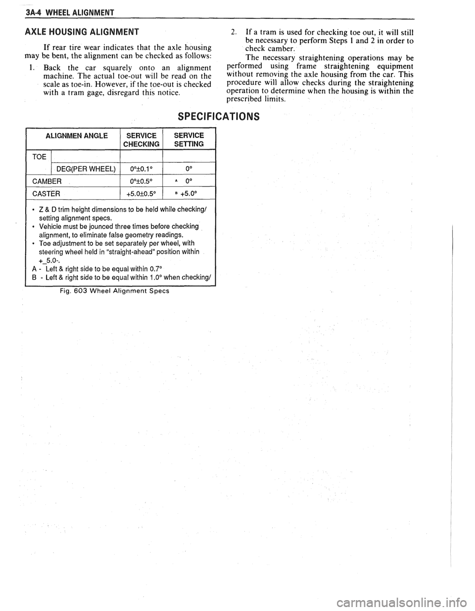
SPECIFICATIONS
1 CASTER 1 +5.0+0.5O 1 +5.0° 1
TOE
* Z & D trim height dimensions to be held while checking1
setting alignment specs.
* Vehicle must be jounced three times before checking
alignment, to eliminate false geometry readings.
Toe adjustment to be set separately per wheel, with
steering wheel held in "straight-ahead" position within
+-5.0-.
A - Left & right side to be equal within 0.7"
B - Left & right side to be equal within 1 .OO when checking1
Fig. 603 Wheel Alignment Specs
DEG(PER WHEEL)
CAMBER OO+O.10 0°
O0+O.5O A 0°
Page 188 of 1825
STEERING LINKAGE 3B6-1
SECTION 3B6
STEERING LINKAGE
The following notice applies to one or more steps in the assembly
procedure of components in this portion of the manual as Notice indicated at
appropriate locations by the terminology "See Caution on Page
1 of this
Section
" .
NOTICE: These fasteners are important attaching parts in that they
could affect the performance of vital components and systems,
andlor could
result in major repair expense. They must be replaced with one of the same
part number or with an equivalent part if replacement becomes necessary. Do
not use a replacement part of lesser quality or substitute design. Torque
values must be used as specified during reassembly to assure proper retention
of these parts. For prevailing torque
nut(s) and bolt(s), refer to the "Reuse of
Prevailing Torque
Nut(s) and Bolt(s)" chart in Section 10.
CONTENTS
General Description ........................................... 3B6- 1 Relay Rod ............................................................ 3B6-3
Maintenance and Adjustments ............................... 3B6- I Idler Arm ............................................................. 3B6-4
On-Car Service ........................................................ 3B6-2 Pitman Arm ......................................................... 3B6-5
Tie Rods .............................................................. 3B6-2 Specifications ........................................................... 3B6-6
GENERAL DESCRIPTION
A parallelogram type steering linkage connects both
steering gear. The right end of the relay rod is supported by
front wheels to the steering gear through the
pitman arm,
the idler arm which pivots on a support attached to the
The right and left tie rods are attached to the steering arms
frame rail. The
pitman arm and idler arm remain parallel to
and to the relay rod by ball studs. The left end of the relay
each other while they move through symmetrical arcs. See
rod is supported by the
pitman arm, which is driven by the Fig. 3B6-2.
MAONTENANCE AND ADJUSTMENTS
CHELKlNC STtLRING LINKAGE WEIR A? VltlItD FROhl ABOVL
POSITION DIAL INDICATOR
-TO CHECK MOVEMENT
AT THIS POINT
FRONT
OF
MOVE WHEEL IN AND OUT AT FRONT AND BACK
Fig. 3B6-1--Checking Linkage Wear
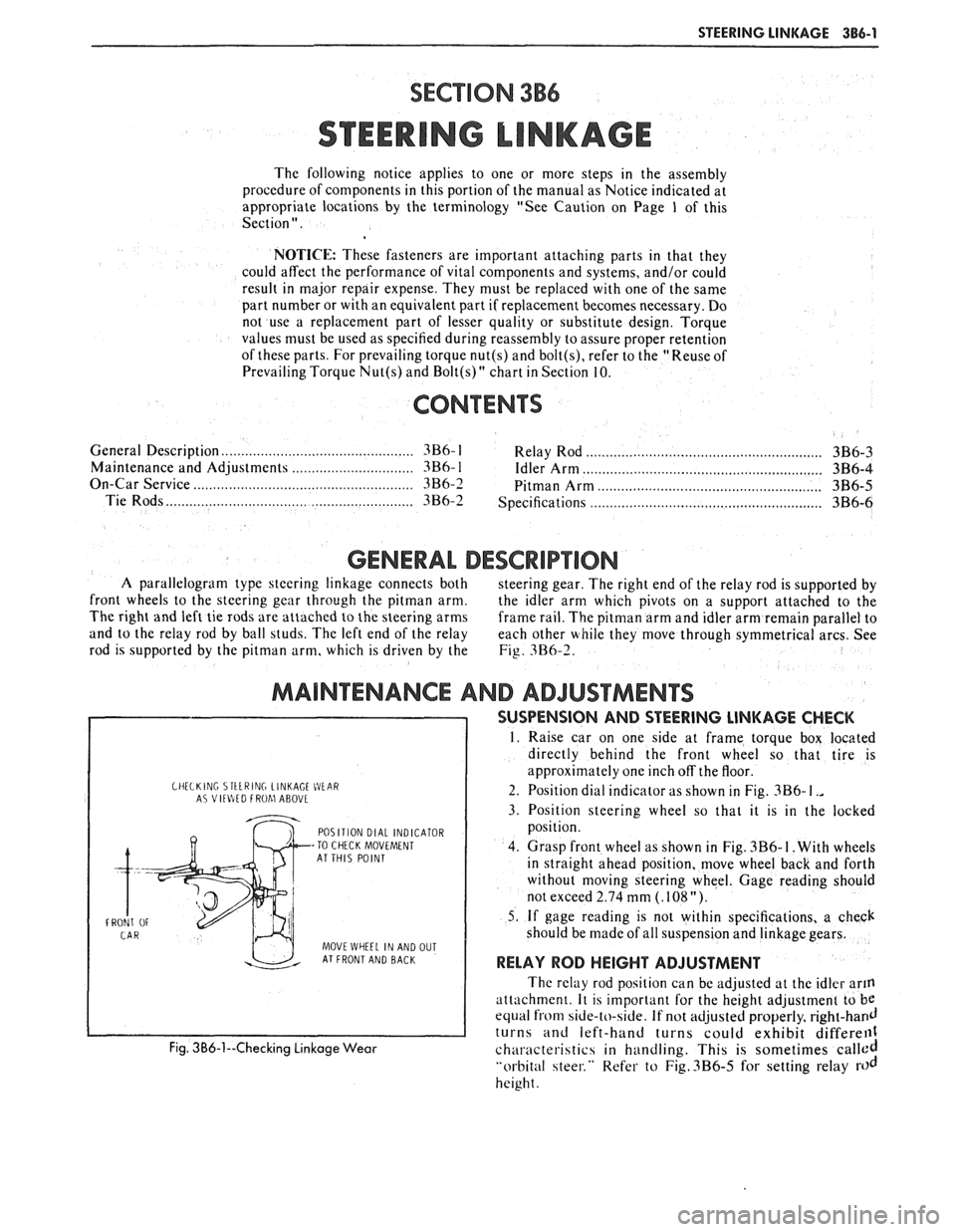
SUSPENSION AND STEERING LINKAGE CHECK
1. Raise car on one side at frame torque box located
directly behind the front wheel so that tire is
approximately one inch off the floor.
2. Position dial indicator as shown in Fig.
3B6- I .,
3. Position steering wheel so that it is in the locked
position.
4. Grasp front wheel as shown in Fig.
3B6- I. With wheels
in straight ahead position, move wheel back and forth
without moving steering wheel. Gage reading should
not exceed 2.74 mm
(. 108 ").
5. If gage reading is not within specifications, a check
should be made of all suspension and linkage gears.
RELAY ROD HEIGHT ADJUSTMENT
The relay rod position can be adjusted at the idler arm
attach men^. It is important for the height adjustment to be
equal from side-to-side. If not adjusted properly, right-hand
turns and left-hand turns could exhibit differell1
characteristics in handling. This is sometimes called
"orbital steer." Refer to Fig.3B6-5 for setting relay rod
height.
Page 190 of 1825
STEERING LINKAGE 386-3
ADJUSTER SLEEVE SLOT
HORIZONTAL
NOTE Slot Iri adjuster
sleeve must not be
w~th~n th~q area of
clamp laws.
ROTATION NOTE Must have mlnlmum slot
shown after torqulng tie rod
TIE ROD-INNER
RELAY ROD
CAUTION Clamp must be between & clear of d~mples before torqulng
TIE ROD-OUTER
NOTE Equal w~th~n three
threads, must be vis~ble at Inner and outer ends of adjuster sleeve when
assembled to steerlng
Torque Nuts 19 N m (14 Ft Lbs
Fig. 3B6-4--Tie Rod Clamp and Sleeve Orientation
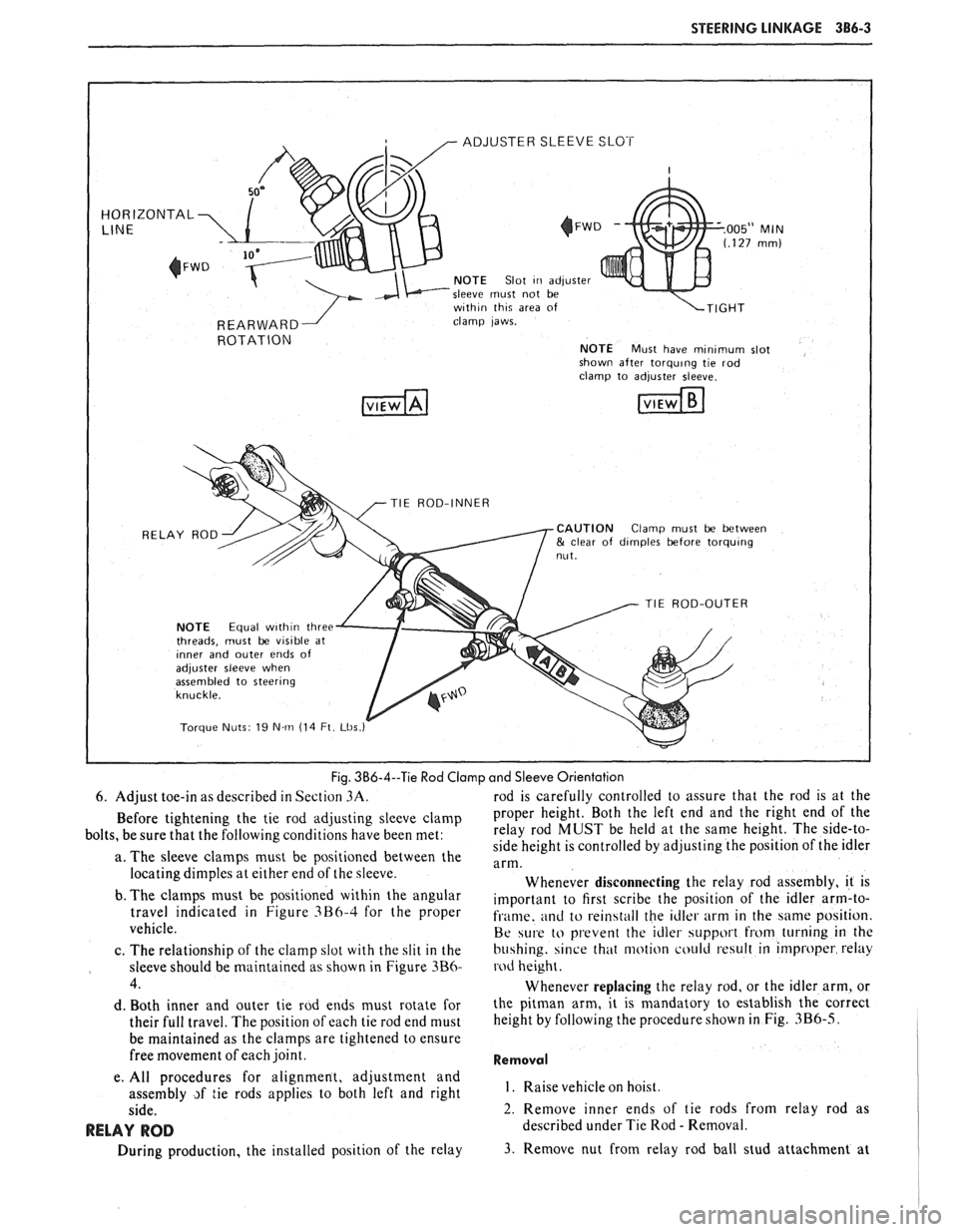
6. Adjust toe-in as described in Section
3A. rod is carefully controlled to assure that the rod is at the
Before tightening the tie rod adjusting sleeve clamp Proper height. Both the left end and the right end of the
bolts, be sure that the following conditions have been met: relay
rod MUST be held at the same height. The side-to-
side height is controlled by adjusting the position of the idler
a. The sleeve clamps must be positioned between the
arm. locating dimples at either end of the sleeve.
Whenever disconnecting the relay rod assembly, it is
b. The
clalnps must be positioned within the angular important to first scribe the position of the idler arm-to- travel indicated in Figure 3B6-4 for the Proper fi.ame. and to rein4tall the idler arm in the same position.
vehicle.
Be w1.e to prevent the idler support hom turning in the
c. The relationship of the clamp slot with the slit in the
bu4hing. since that motion could result in improper relay
sleeve should be maintained as shown in Figure
3B6- rod height.
4. Whenever replacing the relay rod, or the idler arm, or
d. Both inner and outer tie rod ends must rotate for the pitman arm, it is mandatory to establish the correct
their full travel. The position of each tie rod end must height
by following the procedure shown
in Fig. 3B6-5.
be maintained as the clamps are tightened to ensure
free movement of each joint.
Removal
e. All procedures for alignment, adjustment and
assembly
~f tie rods applies to both left and right I. Raise vehicle hoist.
side. 2. Remove inner ends of tie rods from relay rod as
RELAY ROD described under Tie Rod - Removal.
During production, the installed position of the relay
3. Remove nut from relay rod ball stud attachment at
Page 1158 of 1825
CLUTCH 7C-4
SECTION 76
CLUTCH
CONTENTS
GENERAL DESCRIPTION .......................... .. ............................................................. 7C-I
DIAGNOSIS ...................................................................................................................... 7C-3
Preliminary Checks ....................... ... ............................................................................ 7C-2
Bleeding Hydraulic Clutch System ................... .. .......................................................... 7C-2
ON-VEHICLE SERVICE ................................................................................................. 7C-5
Clutch Hydraulic System ................................................................................................. 7C-5
..................... Pressure Plate and Disc .. ........................................................................... 7C-6
Clutch Pedal ..................................................................................................................... 7C-6
Pilot Bearing .................................................................................................................. 7C-6
....................................................................................................... SPECIFICATIONS 7C-8
............................................................................................................ SPECIAL TOOLS 7C-8
GENERAL DESCRIPTION
COMPONENTS
The principal parts of a clutch system are: the
driving member and the operating members. Figure
7C-1 shows an exploded view of the clutch system.
DRIVEN MEMBERS (FIGURES 7C-1 AND 7C-2)
The driven member is the clutch disc with a
splined hub which is free to slide lengthwise along the
splines of the input shaft, but which drives the input
shaft through these same splines.
The driving and driven members are held in
contact by spring pressure. This pressure is exerted by
a diaphragm spring in the pressure plate assembly.
HYDRAULIC CLUTCH (FIGURE 7C-3)
A hydraulic clutch operating mechanism is used
on all models. The
mechanism consist of a remote
reservoir, clutch master cylinder and slave cylinder.
The remote reservoir is mounted to a bracket which
bolts to the power brake booster. The clutch master
cylinder is mounted on the cowl panel and the slave
cylinder is mounted on the bell housing. The clutch
master cylinder is operated directly off the clutch
pedal.
When the clutch pedal is pressed down, hydraulic
fluid under pressure from the clutch master cylinder
flows into the slave cylinder. Since the piston is also
connected to the clutch fork this lever moves the
release bearing into contact with the clutch cover
release fingers to disengage the clutch. The hydraulic
clutch system locates the clutch pedal height and
provides automatic clutch adjustment. No adjustment
of clutch linkage or pedal position is required.
OPERATING MEMBERS (FIGURE 7C-3)
HYDRAULIC CLUTCH FLUID
When adding fluid to or refilling the system after
The clutch release system is operated by service operations use GM Delco Supreme No. 11 hydraulic pressure and consists of the clutch pedal, brake fluid or an equivalent fluid that meets DOT 3 clutch master cylinder, clutch slave cylinder, clutch specifications. fork and clutch release bearing.
NOTICE: Do not use mineral or paraffin base oil in
the Clutch Hydraulic System. These fluids will
damage the rubber parts in the cylinders.
Page 1746 of 1825
procedure or glass breakage and
personal injury could occur.
The compartment lift window assembly height,
fore and aft and side adjustments are controlled at the
hinge-to-body location. This area of the body has
oversize hinge attaching holes (Fig. 3) in addition to
the hinge-to-body spacers. Adjustments at the hinge
location must be made with gas supports disengaged.
Additional height adjustment can also be made at the
lower panel by adjusting the rubber bumpers. Bolts
holding hinge to body should be tightened 20 to 28
N-m (15 to 20 ft-lb).
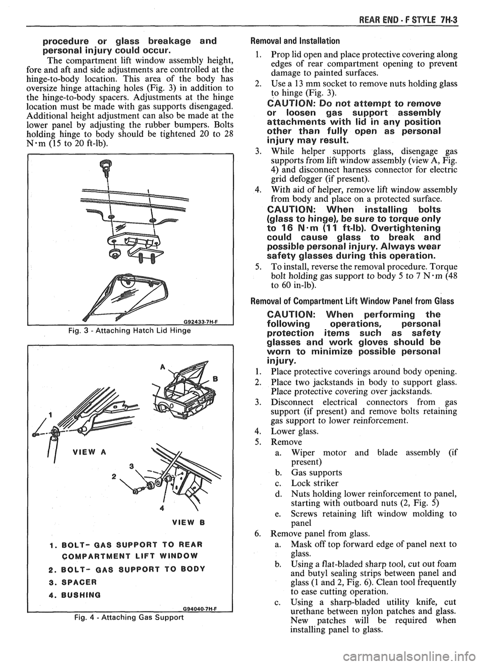
, ,' VIEW A
2
1. BOLT- GAS SUPPORT TO REAR
COMPARTMENT
LIFT WINDOW
2. BOLT- GAS SUPPORT
TO BODY
3. SPACER
4. BUSHING
Fig. 4 - Attaching Gas Support
REAR END - F STYLE 7W-3
Removal and Installation
1. Prop lid open and place protective covering along
edges of rear compartment opening to prevent
damage to painted surfaces.
2. Use
a 13 mm socket to remove nuts holding glass
to hinge (Fig. 3).
CAUTION: Do not attempt to remove
or loosen gas support assembly
attachments with lid in any position
other than fully open as personal
injury may result.
3. While helper supports glass, disengage gas
supports from lift window assembly (view A, Fig.
4) and disconnect harness connector for electric
grid defogger (if present).
4. With
aid of helper, remove lift window assembly
from body and place on a protected surface.
CAUTION: When installing bolts
(glass to hinge), be sure to torque only
to
16 N-m (1 1 ft-lb). Overtightening
could cause glass to break and
possible personal injury. Always wear
safety glasses during this operation.
5. To install, reverse the removal procedure. Torque
bolt holding gas support to body 5 to
7 N-m (48
to 60 in-lb).
Removal of Compartment Lift Window Panel from Glass
CAUTION: When performing the
following operations, personal
protection
iterns such as safety
glasses and work gloves should be
worn to minimize possible personal
injury.
1. Place protective coverings around body opening.
2. Place two jackstands in body to support glass.
Place protective covering over jackstands.
3. Disconnect electrical connectors from gas
support (if present) and remove bolts retaining
gas support to lower reinforcement.
4. Lower glass.
5. Remove a. Wiper motor and blade assembly (if
present)
b. Gas supports
c. Lock striker
d. Nuts
holding lower reinforcement to panel,
starting with outboard nuts
(2, Fig. 5)
e. Screws
retaining lift window molding to
panel
6. Remove panel from glass.
a. Mask
off top forward edge of panel next to
glass.
b. Using
a flat-bladed sharp tool, cut out foam
and butyl sealing strips between panel and
glass (1 and 2, Fig. 6). Clean tool frequently
to ease cutting operation.
c. Using a sharp-bladed utility knife, cut
urethane between nylon patches and glass.
New patches will be required when
installing panel to glass.