ignition PONTIAC FIERO 1988 Service Repair Manual
[x] Cancel search | Manufacturer: PONTIAC, Model Year: 1988, Model line: FIERO, Model: PONTIAC FIERO 1988Pages: 1825, PDF Size: 99.44 MB
Page 1682 of 1825
GENERAL INFORMATION - F STYLE 1 H-1
SECTION IH
GENERAL NFORMAT
NOTICE: The anti-theft label found on some major sheet metal, engines, and transmissions must be masked
prior to painting, rustproofing, undercoating, etc. The mask
must be removed following the above operations.
Failure to keep the label clean and readable may result in liability for violation of Federal Vehicle Theft Prevention
Standard, and subject the vehicle owner to possible suspicion that the part was stolen.
Lock Cylinder Coding
..................................... I H-1 Chip Resistant Plastisol Material .................... 1 H-8
...................................................... Lubrication 1 H-2 Flexible Exterior Plastic Parts ......................... 1H-9
Adhesive Body Side Moldings ......................... 1H-3 Metal Replacement Parts Finishing ................ lH-13
Waterleak Diagnosis and Repair ..................... 1H-3 Interior Plastic Trim Parts Finishing .............. 1H-13
.................................................... Anticorrosion Treatment ................................ IH-4 Special Tools I H- 14
LOCK CYL!NDER CODING o Check key operation in the lock cylinder.
KEY IDENTIFICATION AND USAGE
REPLACEMENT LOCK CYLINDERS
The lock cylinder keyway is designed so that
other model keys will not enter a current model lock
cylinder. Two noninterchangeable keys are used.
CB Square headed key is used in the ignition lock
cylinder.
o Oval headed key is used in all other lock
cylinders.
Key identification is obtained from the four
character key code stamped on the knockout portion
of the key head and an identification letter stamped on
the key shank. After the code number has been
recorded by the owner, the plugs should be knocked
out of the key head. From these numbers, the lock
combination can be determined by use of a code list
(available to owners of key cutting equipment from
equipment suppliers). If key code numbers are not
available from records or from the knockout plug, the
lock combination (tumbler numbers and position) can
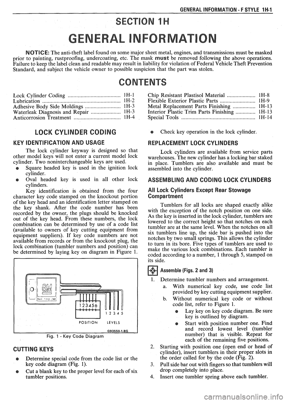
be determined by laying key on diagram in Figure
1.
I POSITION LEVELS I
Fig. 1 - Key Code Diagram
CUTTING KEYS
Lock cylinders are available from service parts
warehouses. The new cylinder has a locking bar staked
in place. Tumblers are also available and must be
assembled into the cylinder.
ASSEMBLING AND CODING LOCK CYLINDERS
All Lock Cylinders Except Rear Stowage
Compartment
Tumblers for all locks are shaped exactly alike
with the exception of the notch position on one side.
As the key is inserted in the lock cylinder, tumblers are
lowered to the correct height so that notches on each
tumbler are at the same level. When the notches on all
six tumblers line up, the side bar is pushed into the
notches by two small springs. This allows the cylinder
to turn in its bore. Five types of tumblers are used to
make the various lock combinations. Each tumbler is
coded according to a number,
1 through 5, stamped on
its side.
Assemble (Figs. 2 and 3)
1. Determine tumbler numbers and arrangement.
a. With numerical
key code, use code list
provided by key cutting equipment supplier.
b. Without numerical
key code or without
code list, refer to Figure
1.
o Lay key on key code diagram. Be sure
key is outlined by diagram.
Determine special code from the code list or the
key code diagram (Fig.
1). 3.
o Cut a blank key to the proper level for each of six
tumbler positions.
4.
Start with position number one. Find
and record lowest level (tumbler
number) that is visible. Repeat for
each of the remaining five positions.
Starting with position one [open end or head of
cylinder), insert tumblers in their proper slots in
the order called for by the code (Fig.
2).
Pull side bar out with fingers so that tumblers will
drop completely into place.
Insert one tumbler spring above each tumbler.
Page 1703 of 1825
2H-6 STATIONARY GLASS - F STYLE
all traces of factory installed adhesive must be
removed prior to reinstallation.
5. Wipe sanded mirror support with clean paper
towel saturated with alcohol and allow to dry.
6. Follow directions on manufacturer's kit to
prepare
rearview mirror support prior to
installation on glass.
7. Properly position support to its premarked
location, with rounded end pointed upward; press
support against glass for 30 to 60 seconds,
exerting steady pressure against glass. After five
minutes, any excess adhesive may be removed
with an alcohol moistened paper towel or glass
cleaning solution.
8. Reinstall mirror
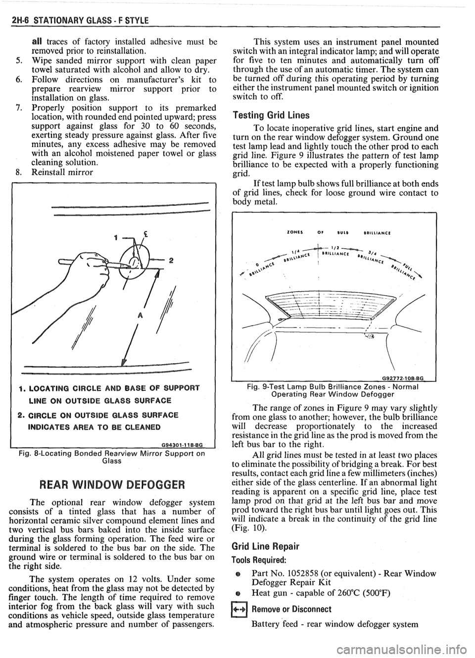
4. LOCATING CIRCLE AND BASE OF SUPPORT
LINE ON OUTSIDE GLASS SURFACE
2. CIRCLE ON OUTSIDE GLASS SURFACE
INDICATES AREA TO BE CLEANED
G94301-11 B.BG
Fig. 8-Locating Bonded earv view Mirror Support on
Glass
REAR WlMBOW DEFOGGER
The optional rear window defogger system
consists of a tinted glass that has a number of
horizontal ceramic silver compound element lines and
two vertical bus bars baked into the inside surface
during the glass forming operation. The feed wire or
terminal is soldered to the bus bar on the side. The
ground wire or terminal is soldered to the bus bar on
the right side.
The system operates on 12 volts. Under some
conditions, heat from the glass may not be detected by
finger touch. The length of time required to remove
interior fog from the back glass will vary with such
conditions as vehicle speed, outside glass temperature
and atmospheric pressure and number of passengers. This
system uses an instrument panel mounted
switch with an integral indicator lamp; and will operate
for five to ten minutes and automatically turn off
through the use of an automatic timer. The system can
be turned off during this operating period by turning
either the instrument panel mounted switch or ignition
switch to off.
Testing Grid Lines
To locate inoperative grid lines, start engine and
turn on the rear window defogger system. Ground one
test lamp lead and lightly touch the other prod to each
grid line. Figure
9 illustrates the pattern of test lamp
brilliance to be expected with a properly functioning
grid.
If test lamp bulb shows full brilliance at both ends
of grid lines, check for loose ground wire contact to
body metal.
Fig. 9-Test Lamp Bulb Brilliance Zones - Normal
Operating Rear Window Defogger
The range of zones in Figure 9 may vary slightly
from one glass to another; however, the bulb brilliance
will decrease proportionately to the increased
resistance in the grid line as the prod is moved from the
left bus bar to the right.
All grid lines must be tested in at least two places
to eliminate the possibility of bridging a break. For best
results, contact each grid line a few millimeters (inches)
either side of the glass centerline. If an abnormal light
reading is apparent on a specific grid line, place test
lamp prod on that grid at the left bus bar and move
prod toward the right bus bar until light goes out. This
will indicate a break in the continuity of the grid line
(Fig.
10).
Grid Line Repair
Tools Required:
o Part No. 1052858 (or equivalent) - Rear Window
Defogger Repair Kit
e Heat gun - capable of 260°C (500°F)
Remove or Disconnect
Battery 'feed - rear window defogger system
Page 1766 of 1825
ROOF - F STYLE 8H-7
SECTION A-A VIEW A
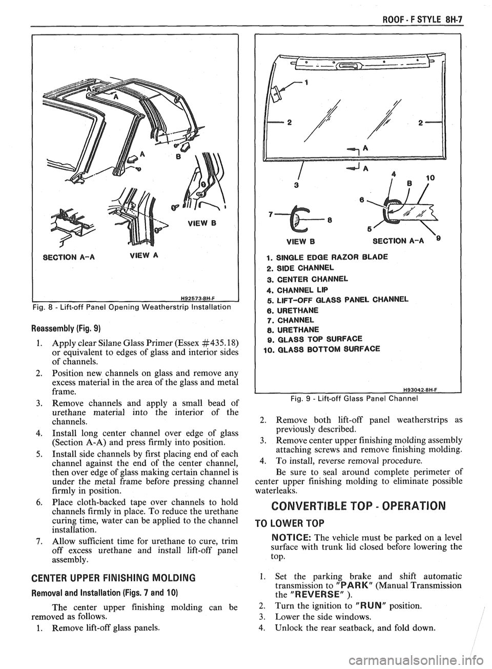
Fig. 8 - Lift-off Panel Opening Weatherstrip Installation
Reassembly (Fig. 9)
1. Apply clear Silane Glass Primer (Essex #435.18)
or equivalent to edges of glass and interior sides
of channels.
2. Position new channels on glass and remove any
excess material in the area of the glass and metal
frame.
3. Remove channels and apply a small bead of
urethane material into the interior of the
channels.
4. Install long center channel over edge of glass
(Section A-A) and press firmly into position.
5. Install side channels by first placing end of each
channel against the end of the center channel,
then over edge of glass making certain channel is
under the metal frame before pressing channel
firmly in position.
6. Place cloth-backed tape over channels to hold
channels firmly in place. To reduce the urethane
curing time, water can be applied to the channel
installation.
7. Allow sufficient time for urethane to cure, trim
off excess urethane and install lift-off panel
assembly.
CENTER UPPER FINISHING MOLDING
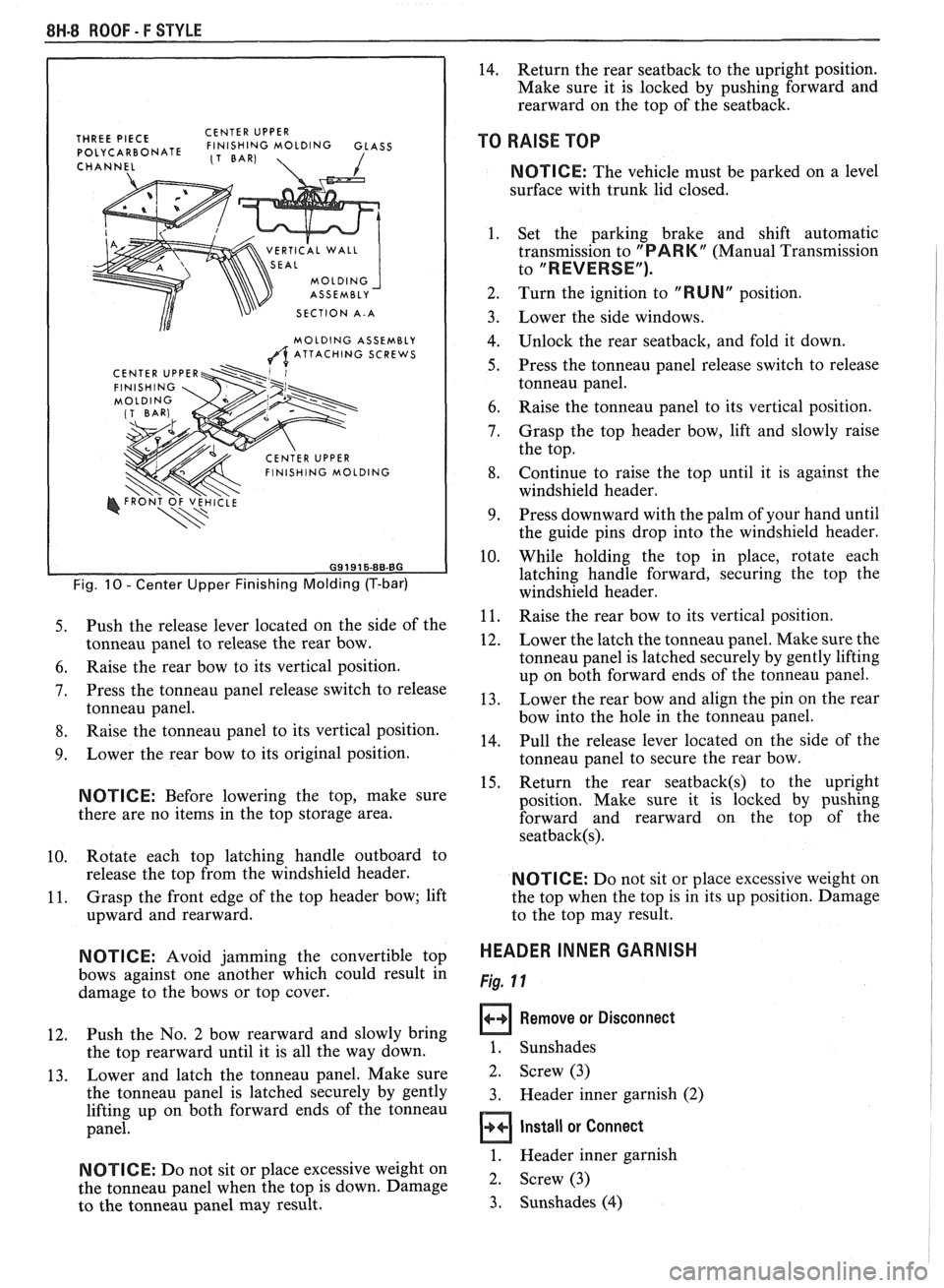
Removal and Installation (Figs. 7 and 10)
The center upper finishing molding can be
removed as follows.
1. Remove lift-off glass panels.
1 VlEWB SECTION A-A
1. SINGLE EDGE RAZOR BLADE
2. SIDE CHANNEL
3. CENTER CHANNEL
4. CHANNEL LIP
5. LIFT-OFF GLASS PANEL CHANNEL
6. URETHANE
7. CHANNEL
8. URETHANE
9. GLASS TOP SURFACE
10. GLASS BOTTOM SURFACE
Fig. 9 - Lift-off Glass Panel Channel
2. Remove both lift-off panel weatherstrips as
previously described.
3. Remove center upper finishing molding assembly
attaching screws and remove finishing molding.
4. To install, reverse removal procedure.
Be sure to seal around complete perimeter of
center upper finishing molding to eliminate possible
waterleaks.
CONVERTIBLE TOP - OPERATION
TO LOWER TOP
NOTICE: The vehicle must be parked on a level
surface with trunk lid closed before lowering the
top.
1. Set the parking brake and shift automatic
transmission to
"PARK" (Manual Transmission
the
"REVERSE" ).
2. Turn the ignition to "RUNN position.
3. Lower the side windows.
4. Unlock the rear seatback, and fold down.
Page 1767 of 1825
8H.8 ROOF - F STYLE
THREE PIECE CENTER
UPPER POLYCARBONATE FINISHING MOLDING GLASS (1 BAR)
CHANNEL 1
VERTICAL WALL
SECTION A-A
MOLDING ASSEMBLY
A ATTACHING SCREWS
Fig. 10 - Center Upper Finishing Molding (T-bar)
5. Push the release lever located on the side of the
tonneau panel to release the rear bow.
6. Raise the rear bow to its vertical position.
7. Press the tonneau panel release switch to release
tonneau panel.
8. Raise the tonneau panel to its vertical position.
9. Lower the rear bow to its original position.
NOTICE: Before lowering the top, make sure
there are no items in the top storage area.
10. Rotate
each top latching handle outboard to
release the top from the windshield header.
11. Grasp
the front edge of the top header bow; lift
upward and rearward.
N OTI C E: Avoid jamming the convertible top
bows against one another which could result in
damage to the bows or top cover.
12. Push the
No. 2 bow rearward and slowly bring
the top rearward until it is all the way down.
13. Lower
and latch the tonneau panel. Make sure
the tonneau panel is latched securely by gently
lifting up on both forward ends of the tonneau
panel.
NOTICE: Do not sit or place excessive weight on
the tonneau panel when the top is down. Damage
to the tonneau panel may result.
14. Return the rear seatback to the upright position.
Make sure it is locked by pushing forward and
rearward on the top of the seatback.
TO RAISE TOP
NOTICE: The vehicle must be parked on a level
surface with trunk lid closed.
1. Set the parking brake and shift automatic
transmission to
"PARK" (Manual Transmission
to
"REVERSE").
2. Turn the ignition to "RUN" position.
Lower the side windows.
Unlock the rear seatback, and fold it down.
Press the tonneau panel release switch to release
tonneau panel.
Raise the tonneau panel to its vertical position.
Grasp the top header bow, lift and slowly raise
the top.
Continue to raise the top until it is against the
windshield header.
Press downward with the palm of your hand until
the guide pins drop into the windshield header.
While holding the top in place, rotate each
latching handle forward, securing the top the
windshield header.
Raise the rear bow to its vertical position.
Lower the latch the tonneau panel. Make sure the
tonneau panel is latched securely by gently lifting
up on both forward ends of the tonneau panel.
Lower the rear bow and align the pin on the rear
bow into the hole in the tonneau panel.
Pull the release lever located on the side of the
tonneau panel to secure the rear bow.
Return the rear
seatback(s) to the upright
position. Make sure it is locked by pushing
forward and rearward on the top of the
seatback(s).
NOTICE: Do not sit or place excessive weight on
the top when the top is in its up position. Damage
to the top may result.
HEADER INNER GARNISH
Fig. 11
Remove or Disconnect
1. Sunshades
2. Screw (3)
3. Header inner garnish (2)
Install or Connect
1. Header inner garnish
2. Screw (3)
3. Sunshades
(4)
Page 1784 of 1825
SEATS - F STYLE 9H-1
SEC"IC"0N 9H
SEATS
NOTICE: Lap belt to floor pan and shoulder belt to roof panel or quarter panel fasteners are important
attaching parts in that they could affect the performance of vital parts and systems, and/or could result in major
repair expense. They must be replaced with one of the same part number or with an equivalent part if replacement
becomes necessary. Do not use a replacement part of lesser quality or substitute design. Torque values must be
used as specified during reassembly to assure proper retention of these parts.
CONTENTS
Restraint Systems ........................................... 9H- 1
Lap and Shoulder Belts
............................... 9H-1
Comfort Lock Operational Checks
and Requirements
.................................... 9H- 1
Front Seat Shoulder Belt Retractor
............ 9H-2
Child Seat
...................................................... 9H-2
............................... .................. -.rant Seats .. 9H-5
Mead Restraint
............................................. 9H-5
Reclining
Seatback ................................... 9H-6
Front
Seatback ........................................... 9H-7
Inertia Lock Check
...................................... 9H-7
............................... Manual Recliner Check 9H-7
........................... Seat Torque Specifications 9H-8
Manual Seat
- Diagnosis Chart ................... 9H-8
..................... Power Seat - Diagnosis Chart 9H-9
RESTRAINT SYSTEMS
LAP
AND SHOULDER BELTS
The front seat belts incorporate a 4-to-8 second
fasten seat belt reminder lamp and sound signal
designed to remind the driver if the lap and shoulder
belts are not fastened when the ignition is turned to the
on position. If the driver's seat belt
is buckled, the
alarm will not operate; however, the fasten seat belt
xminder lamp will stay on for a 4-to-8 second period.
,, the driver's seat belt is not buckled, the reminder
lamp and sound signal will automatically shut off after
the 4-to-8 second interval. To diagnose a system
failure, refer to Seat Belt Reminder
Lamp/Alarm
Diagnosis in Section 8A.
The shoulder belt is attached to the front seat lap
belt latch plate and connected to an inertia locking
retractor installed to the roof panel above the right and
left side of the front seat. The shoulder belt remains
unlocked to allow the occupants to move freely while
the vehicle is being operated. When the vehicle
decelerates or changes direction abruptly, the shoulder
belt is locked in position by a pendulum that causes a
locking bar to engage a cog of the retractor mechanism.
The retractor has a comfort lock feature that
allows the occupant to adjust the shoulder belt for
proper fit and comfort. When engaged, the comfort
lock prevents full retraction of the webbing to eliminate
occupant discomfort due to webbing load on the
shoulder. The occupant can readjust the comfort lock
during vehicle operation as described below.
When servicing or replacing lap and shoulder
belts, refer to the following precautionary items: Front
Seat Adjustments
............................... 9H- 10
Manual Seat Control Arm Knob
................ 9H-10
Front Seat Assembly
.................................... 9H- 1 1
Seat Adjuster Assembly ............................. 9H-11
Six-way Seat Adjuster .................................. 9H- 12
Power Seat Switch
........................................ 9H-15
Four-way Manual Seat Adjuster
................. 9H-15
Seatback Lock Striker/Side Bar Stop .......... 9H-15
High Performance AQ9 Seat
(2FS87) ......... 9H-15
................. .................................... Rear Seats ... 9H- 19
........................................ Cushion Assembly 9H- 19
................................ Folding Rear Seatback 9H- 19
........................... Seatback Lock Assembly 9H-20
.................................. Seatback Lock Striker 9H-20
1. Lap and shoulder belts will be serviced as follows:
a. Retractor
portion(s) of
front seat lap and
shoulder belt for outboard passenger and
driver.
b. Buckle portion of front seat lap belt for
outboard passenger and driver.
c. All belts other than those mentioned in
above steps a and b will be serviced in
complete sets.
d. Do not intermix standard and deluxe belts
on front or rear seats.
2. Keep sharp edges and damaging objects away
from belts.
3. Avoid bending or damaging any portion of the
belt buckle or latch plate.
4. Do not bleach or dye belt webbing (clean with a
mild soap solution and water).
5. When installing lap or shoulder belt anchor bolt,
start bolt by hand to assure that bolt is threaded
straight.
NOTICE: See NOTICE on page 9H-1 of this
section.
6. Do not attempt repairs on lap or shoulder belt
retractor mechanisms or lap belt retractor covers.
Replace with new service replacement parts.
Comfort Lock Operational Checks and Requirements
The shoulder belt comfort lock feature must
function as follows:
1. Extend the webbing from the retractor to a
distance approximating buckled position.
Page 1818 of 1825
Battery .......................................................... 6D1-2
Brakes
.................................................................. 5-3
................................ Bumper. Energy Absorber 2B-2
........................................... Charging System 6D3- 1
........................................ Cooling and Radiator 6B-3
....................... ................ Cranking System .. 6D2- 1
Cruise Control
................................. 9B-4, 8A-34-0
......................................... Drive Axles (Rear) 4B1-2
Engine Performance
......................................... 6-3
.............................................. Ignition System 6D4-3
Instrument Panel, Gages and
.................................................... Console 8C-3
............................. Miscellaneous Accessories 9G-2
............................................... Power Antenna 9A-2
Power Recirculation Ball
.................................. 3-3
Power Steering Pumps
........................................ 3-4
.............................................. Propeller Shaft 4A- 1
................................................................ Radio 9A-1
.............. Seal Replacement Recommendations 3- 10
........................ . Steering Gear and Pump Leaks 3-10
.............. Strut Dampener and Shock Absorber 3- 12
.................................................... Trim
Height 3- 14
.................................................. Steering Linkage 3-3
Steering, Suspension, Tires and
Wheels
.............................. .. ................. Section 3
Steering Wheels and Columns
............................ 3-4 ......................................................... Vibrations 3- 14
................................................. Wheel Bearing 3-14 .............................................. Wheels and Tires 3- 13
........................... Windshield Wiper System 8El-2
............................................. Digital Cloclc 8A- 150-0
Disc Brake Caliper Assembly
.......................................... (3000/3 100 Series) 5B1
............... ................... General Description .. 5B 1-2 ............................................... On-Car Service 5B 1-2
...................................... Caliper Assembly 5B 1-2
.......................... Shoe and Lining Assembly 5B 1-4
...................................................... Unit Repair
5B 1-4
.......................................... Caliper Overhaul 5B 1-4
?isc Brake Caliper Assembly (3548
Series)
............................................................. 5B6
General Description
....................................... 5B6-2
On-Car Service
............................................... 5B6-2
....................................... Caliper Assembly 5B6-2
.......................... Parking Brake Adjustment 5B6-3
.......................... Shoe and Lining Assembly 5B6-4
Unit Repair
............................... ... .................... 5B6-5
Caliper Overhaul
.......................................... 5B6-5
.......................... Door Lock Relay (Circuit) 8A- 130-0
Driveability and Emissions
........................ Section 6E
Fuel Injection (Port)
..................................... 6E3-1
Index
................................... follows 6E3-(213-2
...................................... Fuel Injection (TB 1) .6E
2- 1
...................................... Index follows 6E2-C 14-4
Drum Brake Assembly
................... ......... Section 5C3
General Description
......................... ... ............ 5C3-1
........................................... On-Car Service 5C3- 1
Backing Plate
........................................ 5C3-7
....................................... Brake Adjustment .5C 3-4
..................................... Brake Components 5C3-1
Parking Brake Adjustment
.......................... 5C3-4
Wheel Cylinder ........................................... 5C3-5 ..................................................... Unit Repair 5C3-7
............................ Wheel Cylinder Overhaul 5C3-7
CHASSIS INDEX m3
E
........................ Electric Rear Window Defogger 9G-2 ............................................ Electrical Diagnosis 88-1
Audible Alarms .............................................. 81%-77
.......................................... Component Data 818-201
.................................................... Headlights 8A- 100
........................ Heating and Air Conditioning 8A-60 .............................................................. Index $A- 1
........................................... Instrument Panel .8 A-82
.................................................. Introduction 8A-2
........................................................... Lights .8 A- 100
............................................ Repair Procedure 88-5 ........................................ Seats and Mirrors 8A- 141
......................................................... Symbols 8A-3
Troubleshooting Procedures ............................ 8A-4
.................................................. ... Windows .. .8 A- 120
............................................... Wiper/Washers .8 A-90
Electronic Glare Control Mirror
........................ 9G-4
.......................... Electronic Instrument Cluster 86-4, 6
Emissions and Driveability
....................................... Fuel Injection (Port) 6E3- 1
....................................... Fuel Injection (TB1) 6E2-1
Engine
.... V-6 2.8L VIN CODE S RPO (LB8) Section 6A2
.... V-8 5.OL VIN E and F, 5.7L VIN 8 Section 6A3
................................................. Cooling Section 6B
Engine Specifications
............................................................ V-6 6A2-26
............................................................. V-8 683-28
General Description
.............................................................. V-6 61 ............................................................. V-8 6A3-1
Lubrication System ........................................................... V-6 ..6A 2- 1
................................................................ V-8 6A3-2
Multi-port Fuel Injection
..................................................... VIN S 8A-20-0
................................................. VIN 8 8A-23-0
............ Throttle Body Injection (VIN E) 8A-22-0
................ Tuned Port Injection (VIN F) 8A-2 1-0
On-Vehicle Service Camshaft
......................................................... V-6 6A2-16
................................ ..................... V-8 .. 6A3-16
Camshaft Bearings
......................................................... V-6 6A2-16
...................................................... V-8 ..6A 3-17
Connecting Rod Bearings
......................................................... V-6 .6A 2- 18
................................................... V-8 6A3-13
...................... Crankcase (Front Cover) .6A
2- 15
............ Crankcase/Camshaft Sensors Section 6E3
Crankshaft
....................................................... V-6 6A2-25
......................................................... V-8 .6A 3-28
......................................... Cylinder Block .6A 3-26
Cylinder Head
.......................................................... V-6 682-12
.......................................................... V-8 6A3-11
Dipstick Tube .............................................. 6A3-7
Engine Assembly
....................................................... V-6 6212
.......................................................... V-8 6A3-27
Exhaust Manifold
........................................................ V-6 .6A 2-9
V-8
....................................................... 6A3-7
Page 1819 of 1825

4 . CHASSIS INDEX
Fitting Pistons ......................................... .6A 2.24
Front (Cover) Crankshaft Oil
Seal
V-6
......................................................... 6A2- 15
V-8
................................................... 6A3- 16
Gear or Sprocket
V-6
......................................................... .6A 2.26
V-8
........................................................ 6A2-28
Honing and Reboring Cylinders ................ 6A2-23
Intake Manifold and Gasket
V-6
......................................................... .6A 2.9
V-8
............................................................ 6A3-6
Main Bearings
V-6
......................................................... .6A 2. 19
V-8
.......................................................... 6A3-20
Oil Filter and Bypass Valve
...................... 6A3-27
Oil Pan and Pump Assembly
V-6
................................................. 6A2.17, 18
V-8
......................................................... 6A3- 18
Oil Seal (Front Cover)
V-6
......................................................... 6A2- 15
V-8 .......................................................... 6A3-16
Piston and Connecting Rod
V-6
......................................................... .6A 2.2 1
V-8
....................................................... .6A 3.23
Piston Rings V-6
......................................................... .6A 2.24
V-8
........................................................ .6A 3.23
Power Train Mounts
V-6
........................................................... .6A 2.7
V-8
.......................................................... 6A3-5
Rear Main Oil Seal
V-6
......................................................... .6A 2.2 1
V-8 ......................................................... .6A 3.22
Rocker Arm Assembly
V-6
............................................................ 6A2-8
V-8 ............................................................ 6A3-8
Rocker Arm and Push Rod
V-6
........................................................... .6A 2.8
V-8
........................................................ 6A3-8
Rocker Arm Studs 6A2- 13
V-6
......................................................... .6A 2. 13
V-8
.......................................................... 6A3-28
Sprocket or Gear Replacement
V-6
......................................................... .6A 2.26
V-8 .......................................................... 6A3-28
Timing Chain and Sprockets
6A2- 15
Torsional Damper
V-6
.......................................................... 6A2- 14
V-8
.......................................................... 6A3- 15
Valves V-6
........................................ .. ............... .6A 2. 14
V-8
......................................................... .6A 2. 15
Valve Guides
V-6
......................................................... .6A 2. 13
V-8
.......................................................... 6A3-14
Valve Lifters
V-6
......................................................... .6A 2. 1 1
V-8
.......................................................... 6A3-10
Valve Mechanism .................................... 6A 10
Valve Seats
V-6
....................................................... .6A 2. 14
V-8
.......................................................... 6A3-14
Valve Spring
.......................................................... V-6 A- 16
............................................................ V-8 6A3-9
................................. Valve Stem Oil Seal .6A 2. 10 Engine Cooling
........................................... Section
6B
Aluminum Radiator Service
............................ 6B-8
Diagnosis
........................................................ 6B-3. 8
Coolant System .............................................. 6B-4
Leak Testing
.................................................. 6B-8
On-Vehicle Pressure Testing
.......................... 6B-9
Repair Methods
........................................... 6B- 10
Special Tools
.............................................. 6B-14
General Description ......................................... .6 B- 1
Coolant Recovery System
.............................. 6B-3
Coolant Temperature Fan Switch
................ 6B-2
Fans
.............................................................. 6B-2
Radiator
...................................................... 6B-1
Radiator Cap
.................................................. 6B-1
Recovery Bottle
.............................................. 6B-2
Temperature Switch
...................................... 6B-2
Thermostat
.................................................... 6B-3
On-Vehicle Service
......................................... 6B- 14
Coolznt Recovery Bottle
............................. .6 B- 16
Electric Cooling Fan
................................... .6 B- 15
Radiator
....................................................... 6B1'
Thermostat ................................................ 5B-, .
Water Pump ................................... .... ......... 6B-15
Service Procedures
............................................ 6B-3
Cooling System Cure
................................. ... 6B-3
Draining and Refilling the
Cooling System
......................................... 6B-7
Drive Belt
................................................... 6B-7
Engine Electrical ...................................... Section 6D
Battery
............................................................. 6D1
Diagnosis
................................................... 6D 1-2
General Description
.................................. 6D 1-1
On-Car Service
.......................................... 6D 1-5
Charging System
............................................... 6D3
Diagnosis
.................................................... 6D3- 1
General Description
.............................. 6D3- 1
On-Vehicle Service
.................................... 6D3-2
Service Procedures
................................. 6D3- 1
Cranking System .......................... ........ ............ 6D2-
Diagnosis .................................................... 6D2- 1 I
General Description .................................. 6D2- 1
On-Car Service
......................................... 6D2J
................ . Engine Wiring .............................. ... 6D
General Description .................................. 6D5- 1
Ignition System
................................................. 6D4
Diagnosis
................................................... 6D4- 1
General Description
............................... 6D4- 1
On-Car Service
.......................................... 6D4-5
Service Procedures
.................................... 6D4-3
Engine Exhaust Systems
...................................... 6F
Engine
- General Information .............................. 6-1
Compression Test
................................................ 6-5
Engine Knock Diagnosis
................................. 6-4
Engine Mechanical
.............................................. 6-3
Engine Performance Diagnosis
.......................... 6-3
Engine Oil Pressure Light
.................................... 8C-3
Engine Performance Specifications
Chart
........................................................ 6E3-C13-3
Evaporator Core
.............................................. 1B 1-24
Exhaust Systems
.......................................... Section 6F
Catalytic Converters
........................................ 6F- 1
Clamp
................................................................ 6F- 1
Component Replacement
.................................. 6F-2
Hangers
......................................................... 6F- 1
Muffler ............................................................. 6F- 1
Removing and Installing Parts ........................ 6F-2
Resonator .......................................................... 6F- 1
Page 1821 of 1825
6- CHASSIS INDEX
Upper Air Outlet Deflectors ...................... 8C-12
Interior Lights ............................................. 8A- 1 17-0
Intermediate Shaft (Steering Column)
.............. 3B5-3
J
Jump Starting .................................................... 6D 1-4
Junction Block
((2238) ................................. 8A-202-2
L
Lamp Monitoring ......................................... 8A- 1 1 1-0
License Plate Lights .............................................. 8B-2
Light Switch
.................................................... 8A- 12-0
Lighting Systems and Horns
...................... Section 8B
General Description ......................................... .8 B- 1
Exterior Lights
............................................ 8B- 1
Horns ....................... .. ................................. 8B-3
On-Car Service
.................................................. 8B-3
Exterior Lights 8B-3
Horns
.............................................................. 8B-9
Replacement Bulb Specifications .................... 8B-10
Lights (Exterior) Electrical Diagnosis
Back-up
...................................................... 8A- 1 12-0
Fog ............................................... 8A- 100.3,10 3.0
Front
Marker/Park/Hazard .................... 8A-110-0
Hazard with Lamp Monitor .................... 8A-103-0
Headlights .................................................. 8A- 100-0
High Level Stop
..................................... 8A-110-0
License .................................................. .8A.110.3, 4
Rear Marker
........................................... .8 A. 1 10.3, 4
Stop ........................................................... 8A-110-1
Tail ......................................................... .8 A. 1 10.3, 4
Tail with Monitor
................ .... ........... 8A- 1 1 1-2
Turn
......................................................... 8A- 1 10-0
Lights (Interior) Electrical
Diagnosis Cargo Compartment
............................. 8A- 1 14- 1
Courtesy
................................................. 8A- 1 14-0
Dome
.................................. .. ...................... 8A- 1 14-0
Glove Box .................................................. 8A- 1 14-0
Lights Dimming
...................................... 8A- 1 17-0
Reading
...................................................... 8A- 1 14-0
Lower Heater Outlet
........................................ 1A-14
Lubrication Fitting Locations .............................. OB-6
M
Maintenance and Lubrication .................... Section OB
Manual Transmission
. 5 Speed 77 mm .... Section 7B
Diagnosis
........... .. ............................................ 7B-2
On-Vehicle Service
.......................................... 7B-3
Repairs
................................... .... .................... 7B- 12
Special Tools
................................................. 7B-20
. Specifications .............................................. 7B 19
Maintenance Items
................................................ OB-2
Master Cylinder
........................................ Section 5A3
General Description
...................................... ..5A 3.2
On-car Sevice
................................................ 5A3-2
Unit Repair ..................................................... .5A 3.2
Master Cylinder Overhaul
......................... .5A 3.2
Master Cylinder Reservoir
......................... .5A 3.3
Metric Fasteners
................................................ OA- 1
Metric-English Conversion Table ..................... .O A. 10
Miscellaneous Accessories
........................ Section 9G
Diagnosis
.......................................................... 9G-2
Dash/Console Mounted Accessory
Switches
.................................................... 9G-4 Electric
Rear Window Defogger
................ 9G-2
Power Remote Control
Rearview
......................... Mirror ...................... .. 9G-2
Rally Gages
................................................. 9G-2
Tachometer
.................................................. 9G-2
..................................... General Description 9G-4
Electric Glare Control Monitor
.................. 9G-4
Electric Rear Window Defogger
................ 9G-2
Power Remote Control
Rearview
Mirror ..................................................... 9G-2
Rally Gages
................................................. 9G-1
Tachometer
................................................. 9G-1
Trip Odometer
............................................ 9G-1
............................................. On-Car Service 9G-4
Power Remote Control Mirror
.................... 9G-4
Rally Gages. Tach
..................................... 9G-4
Rear Window Defogger
.............................. 9G-4
Mirrors..Power ............................................ 8A- 141-0
Automatic
Day/Night ............................. 8A- 143-0
..................................... Defogger. Mirror 8A-61-0
.......................................... Model Identification OA-'
Muffler ................................................................. 6Fi
N
Neutral Start and Back-Up Lamp
Switch
...................................... ..
0
On-Vehicle Service
Air Conditioning
.................................... ... . 1B-20
Automatic Transmission
............................... .7A 1.3
Battery
........................................................ 6D1-5
................................ ......................... Brakes ... 5-7
Bumpers
......................................................... 2B-4
Charging System
.............................. ... ........... 6D3-2
Chassis Sheet Metal
.......................................... 2C-7
Clutch
................................................................ 7C-5
Cranking System
............................................ 6D2-4
Cruise Control ............................................... 9B-6
Disc Brake Caliper Assembly,
3000/3 100 Series .......................................... 5BliC
Disc Brake Caliper Assembly,
3548 Series
................................................... 5B6-3
Drum Brake Assembly .................................... 5C3-1
Engine (V-6) .................................................... 6A2-7
Engine (V-8) ................................................ -6A3-5
Engine Cooling ....................................... .. .... 6B- 14
Front Suspension
........................................... 3C-1
Horns and Lighting System .............................. 8B-3
Ignition System
.............................................. 6D4-5
Instrument Panel, Gages and
Console
.......................................................... 8C-4
Lighting System and Horns
.......................... .... 8B-3
Miscellaneous Accessories
.......................... .... 9G-4
Power Head Assembly
. Tandem
Diaphragm
................................................. 5D-2
Power Steering Gear and Pump
.................... 3B7-3
Propeller Shaft
............................................. 4A-1
.......................... Radio Systems and Antennas 9A-9
Rear Axle
.......................................................... 4B-8
Rear Axle (Borg Warner)
........................... ... 4B 1-7
Steering Linkage ............................................. 3B6-2
........................ Steering Wheels and Columns 3B5-2
Wheel Alignment
......................................... 3A-2
Windshield Wiper
- Washer System ................ 8E-3