instrument cluster PONTIAC FIERO 1988 Service Service Manual
[x] Cancel search | Manufacturer: PONTIAC, Model Year: 1988, Model line: FIERO, Model: PONTIAC FIERO 1988Pages: 1825, PDF Size: 99.44 MB
Page 1407 of 1825
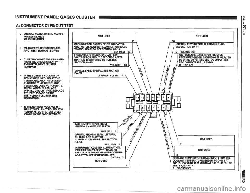
INSTRUMENT PANEL: GAGES CLUSTER I P
A: CONNECTOR 61 PINOUT TEST
a MEASURETO GROUND UNLESS
ANOTHER TERMINAL IS GIVEN
CLUSTER CONNECTOR Cl AS SEEN
IGNITION IS
SWTCHED TO RUN. SEE
FROM THE DRIVER'S SEAT WITH SECTION 8A-75.
* IF THE CORRECT VOLTAGE OR
RESISTANCE IS FOUND AT THE
TERMINALS, AND THE CLUSTER
FUNCTION THAT USES THOSE
TERMINALS DOES NOT OPERATE,
CHECK WIRES. BULBS, AND
PRINTED CIRCUIT. IF OK, REPLACE
EITHER THE GAGE OR THE
INSTRUMENT CLUSTER (SEE
SECTION
86)
* IF THE CORRECT VOLTAGE OR
RESISTANCE IS NOT FOUND AT A
TERMINAL, DO THE TEST GIVEN
OR GO TO THE PAGE REFERRED
NOT USED
NOT USED
260°F
(130°C)T0 1260 OHMS AT 100°F (40°C). DO
Page 1408 of 1825
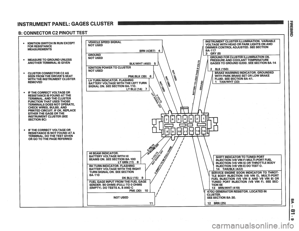
INSTRUMENT PANEL: GAGES CLUSTER I i
B: CONNECTOR 62 PINOUT TEST
0 IGNITION SWITCH IN RUN EXCEPT
FOR RESISTANCE
MEASUREMENTS
0 MEASURETO GROUND UNLESS
ANOTHER TERMINAL IS GIVEN
0 CLUSTER CONNECTOR 62 AS
SEEN FROM THE DRIVER'S SEAT
WlTH THE INSTRUMENT CLUSTER
REMOVED
IF THE CORRECT VOLTAGE OR
RESISTANCE IS FOUND AT THE
TERMINAL, AND THE CLUSTER
FUNCTION THAT USES THOSE
TERMINALS DOES NOT OPERATE.
CHECK WIRES, BULBS, AND
PRINTED CIRCUIT. IF OK. REPLACE
EITHER THE GAGE OR THE INSTRUMENT CLUSTER (SEE
SECTION 86)
IF THE CORRECT VOLTAGE OR
RESISTANCE IS NOT FOUND AT A TERMINAL, DO THE TEST GIVEN
OR GO TO THE PAGE REFERRED VEHICLE
SPEED SIGNAL
NOT USED INSTRUMENT
CLUSTER ILLUMINATION. VARIABLE
VOLTAGE
WlTH HEAD OR PARK LIGHTS ON AND 11 DIMMER CONTROL ADJUSTED. SEE SECTION I
Page 1409 of 1825
INSTRUMENT PANEL: GAGES CLUSTER I P
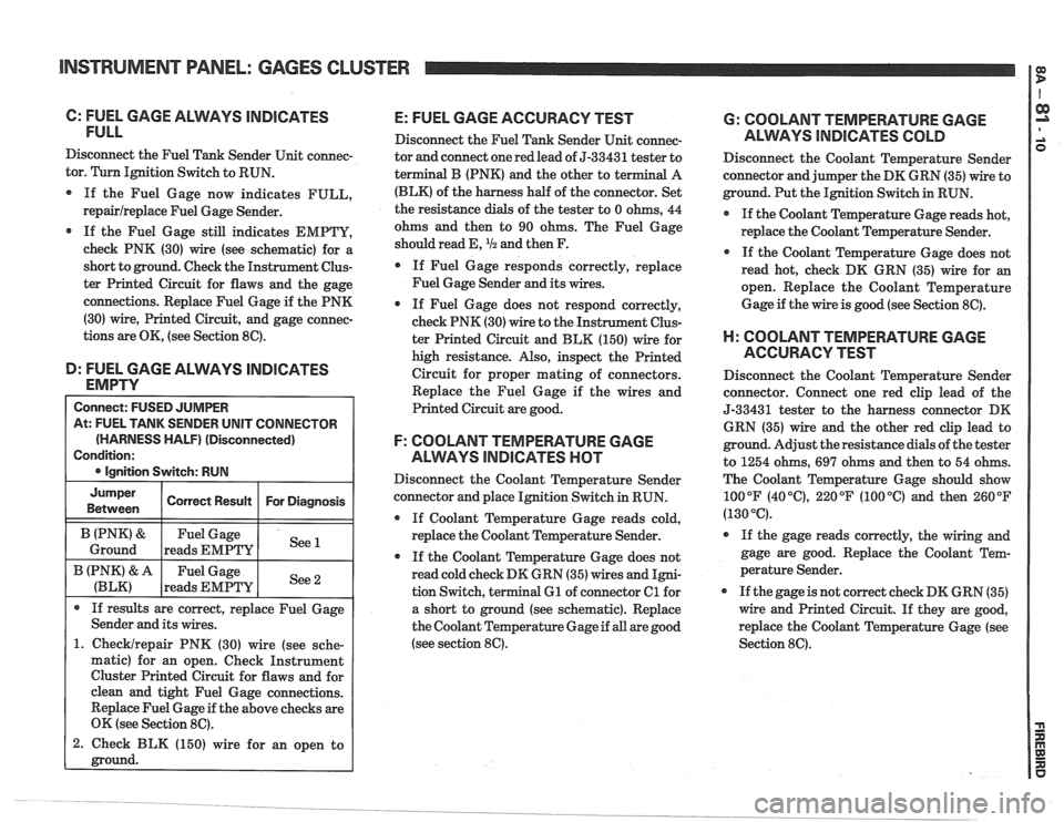
C: FUEL GAGE ALMYS lNDlCPaTES
FULL
Disconnect the Fuel Tank Sender Unit connec-
tor. Turn Ignition Switch to RUN.
If the Fuel Gage now indicates FULL,
repairlreplace Fuel Gage Sender.
@ If the Fuel Gage still indicates EMPTY,
check PNK (30) wire (see schematic) for a
short to ground. Check the Instrument Clus-
ter Printed Circuit for flaws and the gage
connections. Replace Fuel Gage if the PNK
(30) wire, Printed Circuit, and gage connec-
tions are OK, (see Section 8C).
D: FUEL GAGE ALVVAYS lNDlCATES
EMPTY
At: FUEL TANK SENDER UNIT CONNECTOR
(HARNESS HALF)
(Disconnected)
1. Checklrepair PNK (30) wire (see sche-
matic) for an open. Check Instrument
Cluster Printed Circuit for flaws and for
clean and tight Fuel Gage connections.
Replace Fuel Gage if the above checks are
OK (see Section
8C).
2. Check BLK (150) wire for an open to
E: FUEL GAGE ACCURACY TEST
Disconnect the Fuel Tank Sender Unit connec-
tor and connect one red lead of
5-33431 tester to
terminal
B (PNK) and the other to te
(BLK) of the harness half of the connector. Set
the resistance dials of the tester to 0 ohms, 44
ohms and then to 90 ohms. The Fuel Gage
should read E,
I12 and then F.
If Fuel Gage responds correctly, replace
Fuel Gage Sender and its wires.
0 If Fuel Gage does not respond correctly,
check PNK (30) wire to the Instrument Clus-
ter Printed Circuit and BLK (150) wire for
high resistance. Also, inspect the Printed
Circuit for proper mating of connectors.
Replace the Fuel Gage if the wires and
Printed Circuit are good.
F: COOLANT TEMPERATURE GAGE
ALWAYS
INDICATES HOT
Disconnect the Coolant Temperature Sender
connector and place Ignition Switch in RUN.
@ If Coolant Temperature Gage reads cold,
replace the Coolant Temperature Sender.
0 If the Coolant Temperature Gage does not
read cold check DK GRN (35) wires and Igni-
tion Switch, terminal
61 of connector Cl for
a short to ground (see schematic). Replace
the Coolant Temperature Gage if
all are good
(see section
8C).
6: COOLANT TEMPERATURE GAGE
ALWYS INDICATES COLD
Disconnect the Coolant Temperature Sender
connector and jumper the DK GRN (35) wire to
ground. Put the Ignition Switch in RUN.
0 If the Coolant Temperature Gage reads hot,
replace the Coolant Temperature Sender.
If the Coolant Temperature Gage does not
read hot, check DK GRN (35) wire for
an
open. Replace the Coolant Temperature
Gage if the wire is good (see Section
8C).
H: COOLANT TEMPERATURE GAGE
ACCURACY TEST
Disconnect the Coolant Temperature Sender
connector. Connect one red clip lead of the
5-33431 tester to the harness connector DK
GRN (35) wire and the other red clip lead to
ground. Adjust the resistance dials of the tester
to 1254 ohms,
697 ohms and then to 54 ohms.
The Coolant Temperature Gage should show
100°F
(40°C), 220°F (100°C) and then 260°F
(130°C).
If the gage reads correctly, the wiring and
gage are good. Replace the Coolant Tem-
perature Sender.
If the gage is not correct check DK GRN (35)
wire and Printed Circuit. If they are good,
replace the Coolant Temperature Gage (see
Section
8C).
Page 1410 of 1825
INSTRUMENT PANEL: GAGES CLUSTER
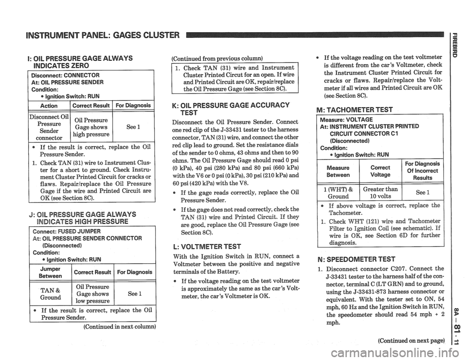
I: OIL PRESSURE GAGE ALWAYS
lEUDlCATES ZERO
At: OIL PRESSURE SENDER
Condition:
lanition Switch: RUN
Action
I Correct Result I For Diagnosis
If the result is correct, replace the Oil
Pressure Sender.
1. Check TAN (31) wire to Instrument Clus-
ter for a short to ground. Check Instru-
ment Cluster Printed Circuit for cracks or
flaws. Repairlreplace the Oil Pressure
Gage if the wire and Printed Circuit are
OK (see Section
86).
Disconnect Oil
Pressure
Sender
J: 81L PRESSURE GAGE ALWAYS
INDICATES
HBGH PRESSURE
(Disconnected)
high pressure
connector
Oil Pressure
Gage shows (Continued
from previous column)
See 1
Cluster Printed Circut for an open. If wire
K: OIL PRESSURE GAGE ACCURACY
TEST
Disconnect the Oil Pressure Sender. Connect
one red clip of the
5-33431 tester to the harness
connector, TAN (31) wire, and connect the other
red clip lead to ground. Set the resistance dials
of the sender to 0 ohms, 43 ohms and then to 90
ohms. The Oil Pressure Gage should read 0 psi
(0
Wa), 40 psi (280 kPa) and 80 psi (660 kPa)
with the V6 or 0 psi (0 kPa), 30 psi (210 kPa) and
60 psi (420
kPa) with the V8.
r If the gage reads correctly, replace the Oil
Pressure Sender.
@ If the gage does not read correctly, check the
TAN (31) wire and Printed Circuit. If they
are good, replace
the Oil Pressure Gage (see
Section 89.
L: VOLTMETER TEST
With the Ignition Switch in RUN, connect a
Voltmeter between the positive and negative
als of the Battery.
If the voltage reading on the test voltmeter
is
approfimately the same as the car's Volt-
meter, the car's Voltmeter is OK. If
the voltage reading on the test voltmeter
is different
from the car's Voltmeter, check
the Instrument Cluster Printed Circuit for
cracks or flaws. Repairlreplace the Volt-
meter if
all wires and Printed Circuit are OK
(see Section 8C).
M: TACHOMETER TEST
At: INSTRUMENT CLUSTER PRINTED
CIRCUIT CONNECTOR 61
(Disconnected)
Condition:
I @ Ignition Switch: RUN I --
For Diagnosis
Of incorrect
Between Results
1 (WRT) & Greater than See Ground 10 volts
@ If above voltage is corred, replace the
Tachometer.
1. Check WHT (121) wire md Tachometer
Filter to
Ignition Coil (see schematic). If
wire is OK, see Section 6D for further
diagnosis.
N: SPEEDOMETER TEST
1. Disconnect connector C207. Connect the
5-33431 tester to the harness half of the con-
nector,
terminal C (LT GRN) and to ground,
using the
5-33431-873 harness connector or
equivalent. With the tester set to ON, 54
mph, 60
HZ and the Ignition Switch in RUN,
the speedometer should read 54 mph
+ 2
mph.
(Continued
in next column)
(Continued on next page)
Page 1412 of 1825
INSTRUMENT PANEL: GAGES CLUSTER
Speedorneter and Odometers
The Speedometer is operated by an electronic
circuit. The Vehicle Speed Sensor (VSS),
located in the transmission, generates an AC
voltage whose frequency is proportional to the
speed of the vehicle. This goes to the Vehicle
Speed Sensor Buffer and then to the Speedom-
eter circuit board in the Instrument Cluster.
The Solid State circuit drives the pointer of the
Speedometer. There is no speedometer cable
in
the vehicle.
The same speed signal from the Vehicle Speed
Buffer is processed by the Speedometer circuit
board to drive the Odometers. They are oper-
ated by a motor that responds to pulses from
the Speedometer circuit.
UpshiN Indicator
With Manual Transmission, the indicator
lights when the car should be shifted to the next
higher gear for better fuel economy. Battery
voltage is applied to one side of the bulb. The
other side of the bulb is switched to ground by
the ECM which uses engine data to compute an
efficient shift point.
Page 1413 of 1825
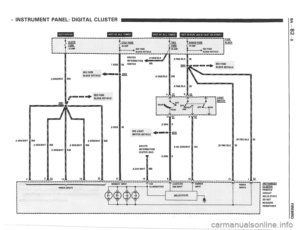
INSTRUMENT PANEL: DIGITAL CLUSTER
I
I
I I SEE FUSE 20 AMP SEE FUSE I
BLOCK DETAILS
CIRCUIT SOLID STATE 00 NOT
MEASURE RESISTANCE
Page 1414 of 1825
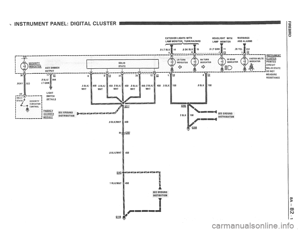
- INSTRUMENT PANEL: DlGlTAL CLUSTER
SEE GROUND
Gll8 - - -
Page 1415 of 1825
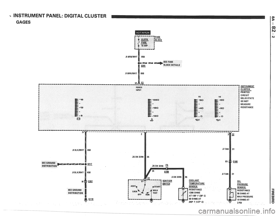
INSTRUMENT PANEL: DIGITAL CLUSTER
GAGES
MAX PRESSURE
Page 1416 of 1825
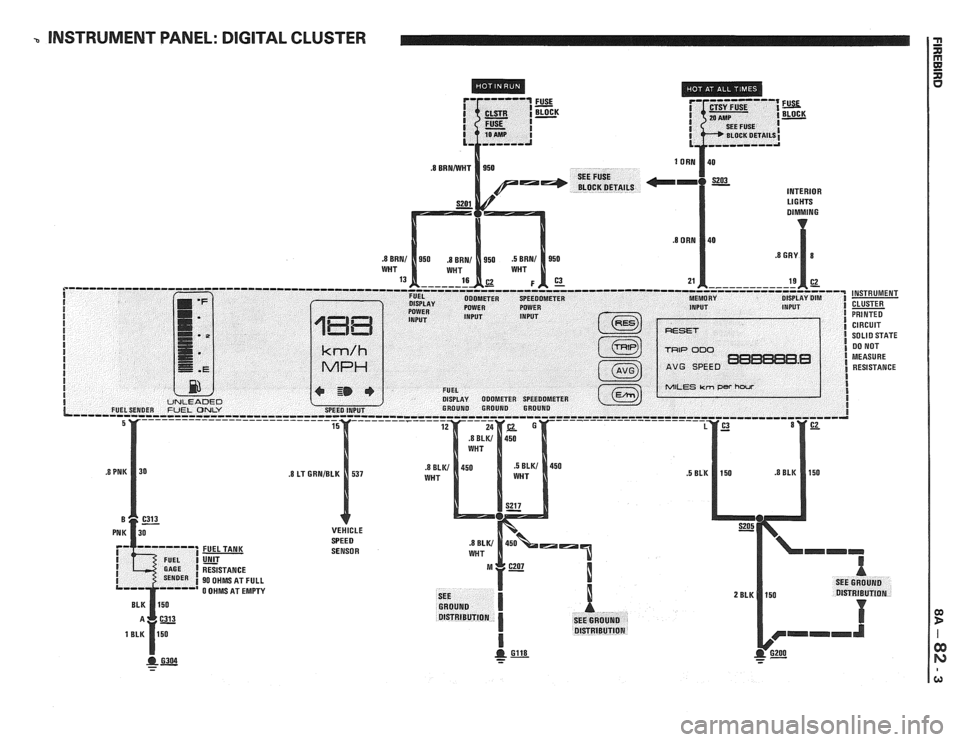
b INSTRUMENT PANEL: DIGITAL CLUSTER
INTERIOR Ll G HTS
SENSOR
- - -
Page 1417 of 1825
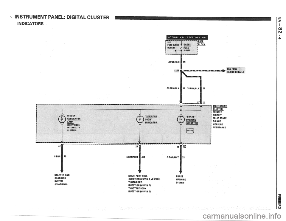
-. INSTRUMENT PANEL: DIGlTAL CLUSTER
INDICATORS
STARTER AND
CHARGING
SYSTEM (CHARGING) MULTIPORT FUEL BRAKE
INJECTION (V6 WIN S,V8 VIM 8) WARNING
TUNED PORT SYSTEM
INJECTION
(V8 VIN F) THROTTLE BODY
INJECTION (V8 WIN E)