coolant PONTIAC FIERO 1988 Service Workshop Manual
[x] Cancel search | Manufacturer: PONTIAC, Model Year: 1988, Model line: FIERO, Model: PONTIAC FIERO 1988Pages: 1825, PDF Size: 99.44 MB
Page 565 of 1825
6EZ-Cl-10 5.OL (VIN El DRIVEABILITY AND EMISSIONS
THROTTLE POSIT ION SENSOR (TPS)
n Remove or Disconnect
1 Air cleaner.
2 Electrical connector.
3 Two TPS attaching screws, lockwashers and
retainers.
4. Sensor.
Install or Connect
1. With throttle valve in the normal closed idle
position, install throttle position sensor on throttle
body assembly, making sure TPS pickup lever is
located ABOVE tang on throttle actuator lever.
2. Retainers and two TPS screws and lockwashers
using a thread locking compound on the screws.
Use loctite 262,
GM part No. 1052624, or
equivalent. Tighten screws.
3. Connector.
4. Air cleaner.
PARKINEUTRAL SWITCH
See Section 8A for location of paruneutral switch. On-
Car Service and Adjustment Procedures are also listed
there.
PARTS INFORMATION
PART NAME GROUP
Controller, ECM ..................... 3.670
Calibrator, PROM .................... 3.670
Sensor, Coolant Temp. ................. 3.682
MAT Sensor ........................ 3.682
Sensor, Exhaust Oxygen ............... 3.682
Sensor, MAP ........................ 3.682
Sensor Kit, Throttle Position ............ 3.764
Switch, Neu Saf and Backing LP ......... 2.698
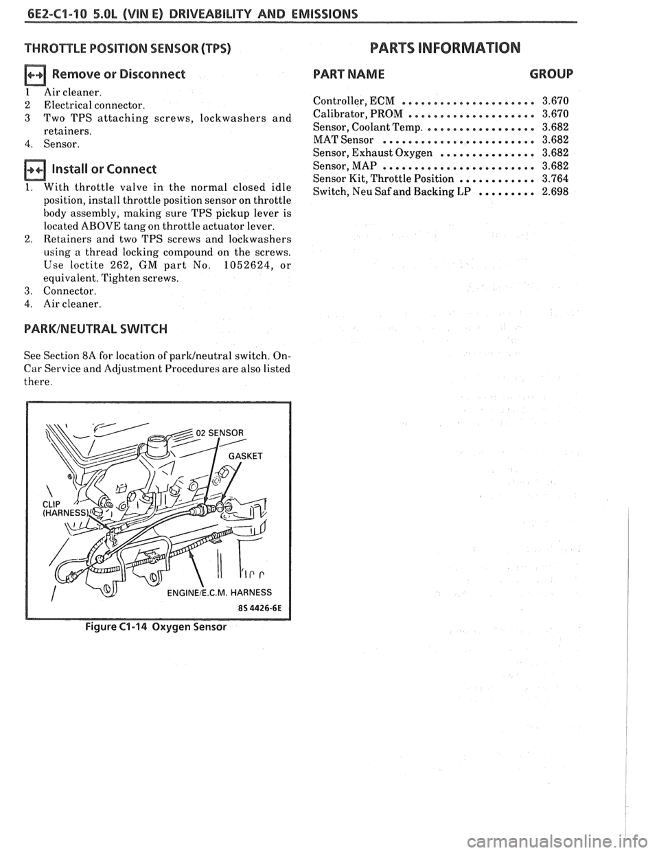
Figure C1-14 Oxygen Sensor
Page 576 of 1825
DRIVEABILIW AND EMISSIONS - 5.OL (VIN E) 6E2-62-1
SECTION C2
FUEL CONTROL SYSTEM
TBI MODEL 228
CONTENTS
GENERAL DESCRIPTION . . . . . . . . . . . . . . . C2-1
PURPOSE ......................... C2-1
MODES OF OPERATION . . . . . . . . . . . . . . C2-1
Starting Mode . . . . . . . . . . . . . . . . . . . C2-1
Clear Flood Mode . . . . . . . . . . . . . . . . C2-2
RunMode . . . . . . . . . . . . . . . . . . . . . . C2-2
Open Loop . . . . . . . . . . . . . . . . . . . . . . C2-2
Closed Loop . . . . . . . . . . . . . . . . . . . . . C2-2
Acceleration Mode . . . . . . . . . . . . . . . C2-2
Deceleration Mode . . . . . . . . . . . . . . . C2-2
Battery Correction Mode . . . . . . . . . . . C2-2
Fuel Cut Off Mode . . . . . . . . . . . . . . . . C2-2
FUEL CONTROL SYSTEM COMPONENTS
. . . C2-2
BASIC SYSTEM OPERATION . . . . . . . . . . . C2-3
THROTTLE BODY INJECTION (TBI) UNIT. . . C2-3
Fuel Injectors . . . . . . . . . . . . . . . . . . . . C2-3
Pressure Regulator . . . . . . . . . . . . . . . C2-3
ldle Air Control (IAC) Valve . . . . . . . . . . C2-4
Throttle Position Sensor (TPS) . . . . . . . . C2-4
FUEL PUMP.. . . . . . . . . . . . . . . . . . . . . . . C2-5
FUEL PUMP ELECTRICAL CIRCUIT . . . . . . . C2-5
DIAGNOSIS . . . . . . . . . . . . . . . . . . . . . . * C2-5
FUEL CONTROL . . . . . . . . . . . . . . . . . . . . C2-5
GENERAL DESCRIPTION
PURPOSE
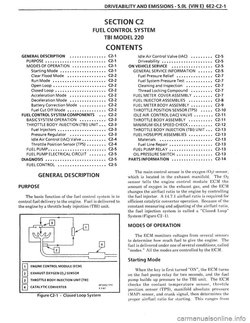
The basic function of the fuel control system is to
control fuel delivery to the engine. Fuel is delivered to
the engine by
a throttle body injection ('FBI) unit.
ENGINE CONTROL MODULE (ECM)
EXHAUST OXYGEN (0,) SENSOR
I 1 THROTTLE BODY INJECTION UNIT (TBI)
CATALYTIC CONVERTER
8P 0352 SYE a 3 81
Figure C2-1 - Closed Loop System
ldle Air Control Valve (IAC) . . . . . . . . . C2-5
Driveability . . . . . . . . . . . . . . . . . . . .. C2-5
ON VEHICLE SERVICE
. . . . . . . . . . . . . . . . . C2-5
GENERAL SERVICE INFORMATION . . . . . . C2-5
Fuel Pressure Relief . . . . . . . . . . . . . . . C2-7
Fuel System Pressure Test . . . . . . . . . . . C2-7
Cleaning and Inspection . . . . . . . . . . . C2-7
Thread Locking Compound . . . . . . . . . C2-7
FUEL METER COVER ASSEMBLY . . . . . . . . C2-7
FUEL INJECTOR ASSEMBLIES . . . . . . . . . . C2-8
FUEL METER BODY ASSEMBLY . . . . . . . . . C2-9
THROTTLE POSITION SENSOR (TPS) . . . . . C2-10
IDLE AIR CONTROL (IAC) VALVE . . . . . . . . C2-11
THROTTLEBODYASSEMBLY .......... C2-11
MINIMUM IDLE SPEED CHECK.. . . . . . . . . C2-12
THROTTLE BODY INJECTION (TBI) UNIT.. . C2-I3
FUEL HOSEIPIPE ASSEMBLIES . . . . . . . . . . C2-13
Materials . . . . . . . . . . . . . . . . . . . . . . C2-13
Fuel Line Repair . . . . . . . . . . . . . . . . . . C2-13
FUEL PUMP RELAY . . . . . . . . . . . . . . . . . . C2-13
OIL PRESSURE SWITCH . . . . . . . . . . . . . . . C2-13
PARTS INFORMATION
. . . . . . . . . . . . . . . . . C2-14
The main control sensor is the oxygen (02) sensor,
which is located in the exhaust manifold. The
O?
sensor tells
the engine control module ECM the
amount of osygen in the exhttust gas, and the ECM
changes the airtfuel ratio to the engine by controlling
the fuel injector.
A 14.7: 1 aidfuel ratio is required for
efficient catalytic converter operation. Because of the
constant measuring and adjusting of the
airlfuel ratio,
the fuel injection system is called a "Closed
IAoopP
System (Figure C2 -1).
MODES OF OPERATION
The ECM monitors voltages from several sensors
to determine how
much fuel to give the engine. The
fuel is delivered under one of several conditions, called
"modes." All the modes are controlled by the ECM.
Starting Mode
When the key is first turned "ON", the ECM turns
on the fuel pump relay for two seconds,
i~nd the l'uel
pump builds up pressure to the TRI unit. The ECM
checks the coolant
temperature sensor, throttle
position sensor
('UPS), manifold absolute pressure
(MAP) sensor, and crank signal, then determines the
proper airtfuel ratio tbr starting. This ranges from
Page 577 of 1825
6EZ-C2-2 DRIVEABILITY AND EMISSIONS - 5.8b (VIN E)
1.5:1 at -36°C (-33°F) to 14.7:1, at 94°C (201°F)
running temperature.
The ECM controls the amount of fuel delivered in
the starting mode by changing how long the injector is
turned "ON" and "OFF". This
is done by "pulsing" the
injector for very short times.
Clear Flood Mode
If the engine floods, clear it by pushing the
accelerator pedal down all the way. The ECM then
pulses the injector at a
20:1 airlfuel ratio, and holds
this injector rate as long as the throttle stays wide
open, and the engine is below 600 rpm. If the throttle
position becomes less than
80%, the ECM returns to
the starting mode.
Run Mode
The run mode has two conditions called "Open
Loop" and "Closed Loop."
Open Loop
When the engine is first started, and it is above
400 rpm, the system goes into "Open Loop" operation.
In "Open Loop," the ECM ignores the signal from the
(02) sensor, and calculates the airlfuel ratio based on
inputs from the coolant temperature and MAP
sensors.
The system stays in "Open Loop" until the
following conditions are met:
1. The
O2 sensor has varying voltage output,
showing that it is hot enough to operate properly.
(This depends on temperature.)
2. The coolant temperature sensor is above a
specified temperature.
3. A specific amount of time has elapsed after
starting the engine.
Closed Loop
The specific values for the above conditions vary
with different engines, and are stored in the
programmable read only memory (PROM). When
these conditions are met, the system goes into "Closed
Loop" operation. In "Closed Loop," the ECM
calculates the
aidfuel ratio (injector on-time) based on
the signal from the
O2 sensor. This allows the aidfuel
ratio to stay very close to 14.7:1.
Acceleration Mode
The ECM looks at rapid changes in throttle
position and manifold pressure, and provides extra
fuel.
Deceleration Mode
When deceleration occurs, the fuel remaining in
the intake manifold can cause excessive emissions and
backfiring. Again, the ECM looks at changes in
throttle position and manifold pressure and reduces
the amount of fuel. When deceleration is very fast, the
ECM can cut off fuel completely for short periods.
Battery Voltage Correction Mode
When battery voltage is low,
the ECM can
compensate for a wealc spark delivered by the
distributor by:
@ Increasing injector on time of fuel delivered;
@ Increasing the idle rpm.
Fuel Cutoff Mode
No fuel is delivered by the injectors when the
ignition is "OFFJ'. This prevents dieseling. Also, fuel
is not delivered if no reference pulses are seen from
the distributor, which means the engine is not
running.
Fuel cutoff also occurs at high engine
rpm, to protect internal engine components from
damage.
FUEL CON"%ROL SYSXM
COMPONENTS
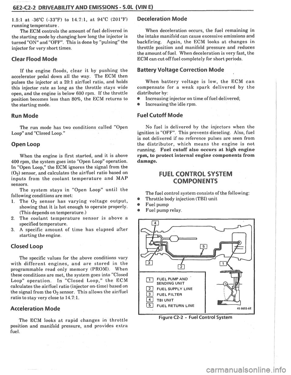
The fuel control system consists of the following:
@ Throttle body injection (TBI) unit
@ Fuel pump
Fuel pump relay.
FUEL PUMP AND
SENDING UNIT
FUEL SUPPLY LINE
16 FUEL RETURN LINE
Figure C2-2 - Fuel Control System
Page 579 of 1825
6EZ-C2-4 DRIVEABILITY AND EMISSIONS - 5.OL (VIN El
[isj FUEL METER COVER bL BODY ASSEMBLIES
1 THROTTLE BODY ASSEMBLY
1 IDLE AIR CONTROL VALVE ASSEMBLY - FILTERED AIR INLET
PlNTLE
TWRO$TLE VAWE
VACUUM PORTS - FOR ENGINE OR EMISSION
CONTROLS
8P 0319-SY 111 5W7
Figure C2-5 - ldle Air Contol System
ldle Air Control (IAC) Valve
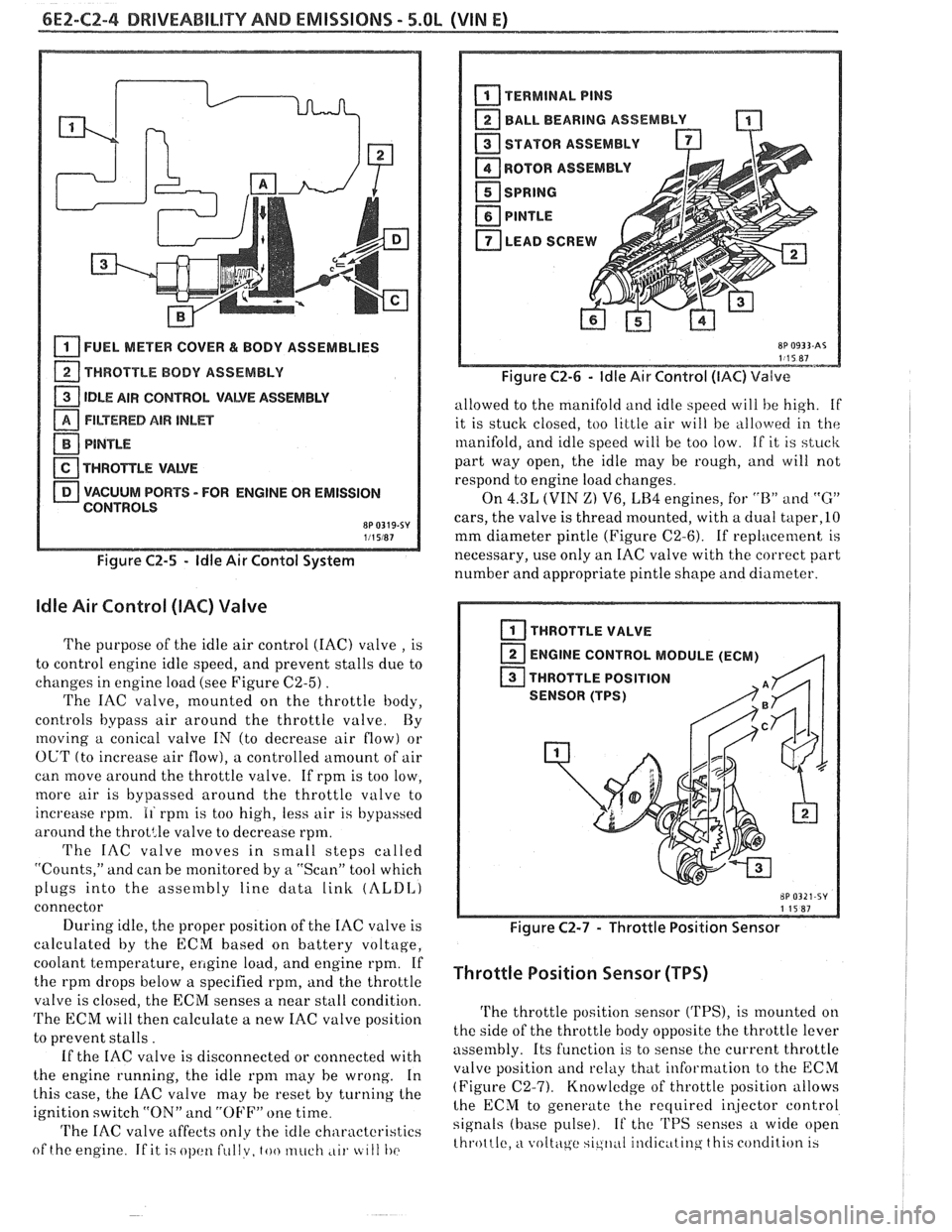
The purpose of the idle air control (IAC) valve , is
to control engine idle speed, and prevent stalls due to
changes in engine load (see Figure
C2-5) .
The IAC valve, mounted on the throttle body,
controls bypass air around the throttle valve By
moving a conical valve IN (to decrease air flow) or
OUT (to increase air flow), a controlled amount of air
can move around the throttle valve. If rpm is too low,
more air is bypassed around the throttle valve to
increase rpm.
11 rpnl is too high, less air is bypassed
around the
throt:le valve to decrease rpm.
The IAC valve moves in small steps called
"Counts," and can be monitored by
a "Scan" tool which
plugs into the assembly line data
link (ALDI,)
connector
During idle, the proper position of the IAC valve is
calculated by the ECM based on battery voltage,
coolant temperature,
ellgine load, and engine rpm. If
the rpm drops below a specified rpm, and the throttle
valve is closed, the ECM senses a near stall condition.
The ECM will then calculate a new IAC valve position
to prevent stalls.
If the IAC valve is disconnected or connected with
the engine running, the idle
rpnl may he wrong. In
this case, the
IAC valve may he reset by turning the
ignition switch "ON" and
"OFF" one time
'I'he IAC valve affects only the idle characteristics
of the engine
If it i.; ol)cltl fullv, too much ,LII. tc 111 I)(>
BALL BEARING ASSEMBLY -
STATOR ASSEMBLY
ROTOR
ASSEMBL
I
SPRING
PlNTLE
LEAD SCREW A
Figure C2-6 - ldle Air Control (IAC) Valve
allowed to the manifold and idle speed will he high. if
it is stuck closed, too little air will be
allo\verl in the
manifold, and idle speed will be too low. If it is stuck
part way open, the idle may be rough, and will not
respond to engine load changes.
On
4.3L (VIN Z) V6, LB4 engines, for "B" and "G"
cars, the valve is thread mounted, with a dual taper,lO
mm diameter pintle (Figure C2-6). If replacement is
necessary, use only an IAC valve with the correct part
number and appropriate pintle shape and diameter.
I THROTTLE VALVE
ENGINE CONTROL MODULE (ECM)
,q
THROTTLE POSITION
SENSOR (TPS)
Figure C2-7 - Throttle Position Sensor
Throttle Position Sensor (TPS)
The throttle position sensor ('I'PS), is mounted on
the side of the throttle body opposite the throttle lever
assembly. Its function is to sense the current throttle
valve position
and relkly that information to the ECM
(Figure (22-7). Knowledge of throttle position allows
lhe ECM to generate the recluired i~jector control
signals (base pulse). If the 'I'PS senses a wide open
throttle,
a voltc\ge sic,ll,~I il~tlic~ttinq this condition 13
Page 597 of 1825
6E2-C3-4 5.OL (VIN E) DRIVEABILITY AND EMISSIONS
428 DK GRNNEL
CHART C-3
CANlSTER PURGE VALVE CHECK
5.OL (VIN E) "F"' SERlES (TBI)
Circuit Description:
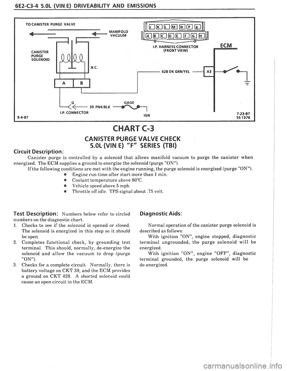
Canister purge is controlled by a solenoid that allows manifold vacuum to purge the canister when
energized. The ECM supplies a ground to energize the solenoid (purge "ON").
If the following conditions are met with the engine running, the purge solenoid is energized (purge "ON").
@ Engine run time after start more than 1 min.
@ Coolant temperature above 80°C.
Vehicle speed above
5 mph.
@ Throttle off idle. TPS signal about .75 volt.
Test Description: Numbers below refer to circled
numbers on the diagnostic chart.
I. Checks to see if the solenoid is opened or closed.
The solenoid is energized in this step so it should
be open.
2. Completes functional check,
by grounding test
terminal. This should, normally, de-energize the
solenoid and allow the vacuum to drop (purge
"ON").
3. Checks for
a complete circuit. Normally, there is
battery voltage on CKT 39, and the ECM provides
a ground on CKT 428.
A shorted sole~oid could
cause an open circuit in the ECM.
Diagnostic Aids:
Normal operation of the canister purge solenoid is
described as follows:
With ignition "ON", engine stopped, diagnostic
terminal ungrounded, the purge solenoid will be
energized. With ignition "ON", engine "OFF", diagnostic
terminal grounded, the purge solenoid will be
de-energized.
Page 600 of 1825
DRIVEABILITY AND EMISSIONS 5.QL (VIN E) 6Ef-C4-1
SECTION C4
IGNITION SYSTEM 1 (EST)
CQN"FEB\BTO
GENERAL DESCRIPTION ............... C4-1
PURPOSE ........................ C4-1
OPERATION
............*......... C4-1
DIAGNOSIS
........................ C4-1
..... RESULTS OF INCORRECT EST OPER. C4-1
HOW CODE 42 IS DETERMINED ....... C4-2
GENERAL DESCRIPTION
PURPOSE
The High Energy Ignition (HE11 system controls
fuel combustion by providing a spark to ignite the
compressed
aidfuel mixture at the correct time. To
provide improved engine performance, fuel economy,
and control of exhaust emissions, the ECM controls
distributor spark advance (timing) with the Electronic
Spark Timing (EST) system.
Only the Electronic Spark 'Timing (EST) system
will be described here. Additional information on the
HE1 system is found in Section 6D.
OPERATION
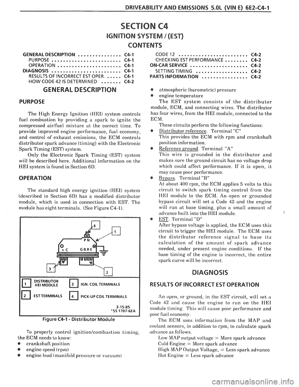
The standard high energy ignition (HEI) system
(described in Section 6D) has a modified distributor
module, which is used in connection with EST.
The
module has eight terminals. (See Figure C4-1).
IGN. COIL TERMINALS
EST TERMINALS PICK-UP
COIL TERMINALS
Figure C4-1 - Distributor Module
To properly control ignition/combustion timing,
the ECM needs to know:
@ crankshaft position
@ engine speed (rpm)
@ engine load (manifold pressure or vacuum)
CODE12 ........................ C4-2
CHECKING EST PERFORMANCE ........ C4-2
ON-CAR SERVICE ...a.e.............. C4-2
SETTING TIMING
.................. C4-2
PARTSINFORMATION ................ C4-2
@ atmospheric (barometric) pressure
@ engine temperature
The EST system consists of the distributor
module, ECM, and connecting wires. The distributor
has four wires, from the
HE1 module, connected to the
ECM.
These circuits perform the following functions:
@ Distributor reference. Terminal "C"
This provides the ECM with rpm and crankshaft
position information.
@ Reference ground. Terminal "A"
'I'his wire is grounded in the distributor and
makes sure the ground circuit has no voltage drop
which could affect performance. If it is open, it
may cause poor performance.
@ Bypass. Terminal "BJ'
At about 400 rpm, the ECM applies 5 volts to this
circuit to switch spark timing control
from the
HE1 module to the ECM. An open or grounded
bypass circuit will set a Code 42 and the engine
will run at base timing, plus a small
amount of
advance built into the
HE1 module.
@ EST. 'Terminal "D"
After bypass voltage is applied, the ECM uses this
circuit to trigger the
HE1 module. The ECM uses
the distributor reference signal to base its
calculation of the amount of spark advance
needed, under present engine conditions.
Lf the
base timing of the engine is incorrect, the entire
spark curve will be incorrect.
RESULTS OF INCORRECT EST OPERATION
An open, or ground, in the EST circuit, will set a
Code 42 and cause the engine to run on the HE1
module timing. 'I'his will cause poor performance and
poor fuel economy.
'I'he ECM uses information from the MAP and
coolant sensors, in addition to rpm, to calculate spark
advance as follows.
I,ow MAP output voltage = More spark advance
Cold Engine
= More spark advance
High
MAP Output Voltage, = Less spark advance
IIot 12ngine = 1,ess spark advance
Page 601 of 1825
6E2-C4-2 5.8L (VIN E) DRIVEABILIW AND EMISSIONS
Therefore, detonation could be caused by low MAP
output or high resistance in the coolant sensor circuit.
Poor performance could be caused by high MAP
o~~tput or low resistance in the coolant sensor circuit.
HOW CODE 42 IS DETERMINED
When the system is running on the HE1 module,
that is, no voltage on the bypass line, the
HE1 module
grounds the EST signal. The ECM expects to see no
voltage on the EST line during this condition. If it
sees a voltage, it sets Code
42 and will not go into the
EST mode. When the rpm for EST is reached (about
400 rpm),
the ECM applies 5 volts to the bypass line and the EST
should no longer be grounded in the
HE1 module, so,
the EST voltage should be varying.
If the bypass line is open, the
HE1 module will not
switch to EST mode, so, the EST voltage will be low
and Code
42 will be set.
If the EST line is grounded, the HE1 module will
switch to EST but, because the line is grounded, there
will be no EST signal and the engine will not run. A
Code
42 may, or may not, be set.
The description, operation, and diagnosis of the
HE1 system are found in Section 6D of this manual.
This section will address diagnosis of that portion of
the Ignition System pertaining to the EST operation.
CODE 12
Code 12 is used during the Diagnostic Circuit
Check procedure to test the code display ability of the
ECM. This code indicates that the ECM is not
receiving the engine rpm (REFERENCE) signal. This
occurs with the ignition key
"ON" and the engine not
running.
The "Reference" signal, also, triggers the fuel
injection system. Without the "Reference" signal, the
engine cannot run.
ON-CAR SERVICE
SETTING TIMING
Set timing according to instructions on Vehicle
Emission Control Information label.
PARTS INFORMATION
PART NAME GROUP
....................... Module, Distr 2.383
......................... Coil, Distr 2.170
Page 620 of 1825
DRIVEABILITY AND EMISSIONS - 5.OL (VIN E) 6E2-C7-1
SECTION C7
EXHAUST GAS RECIRCULAVON (EGR) SYSEENO
GENERAL DESCRIPTION ...............
........................ PURPOSE
OPERATION
......................
EGR CONTROL .....................
...... NEGATIVE BACKPRESSURE VALVE
.......... EGR VALVE IDENTIFICATION
RESULTS OF INCORRECT OPERATION
. . , .
CONTENTS
......................... C7-1 DIAGNOSIS C7-2
..................... C7-1 ON-CAR SERVICE C7-2
....................... C7-1 EGRVALVE C7-2
............. C7-1 EGR Manifold Passage C7-2
C7-1
EGR CONTROL SOLENOID ............. C7-3
C7-2 PARTS INFORMATION
................. C7-3
C7-2
GENERAL DESCRIPTION
PURPOSE
The EGR system is used to lower NO, (oxides of
nitrogen) emission levels caused by high combustion
temperatures.
It does this by decreasing combustion
temperature. The main element of the system is an
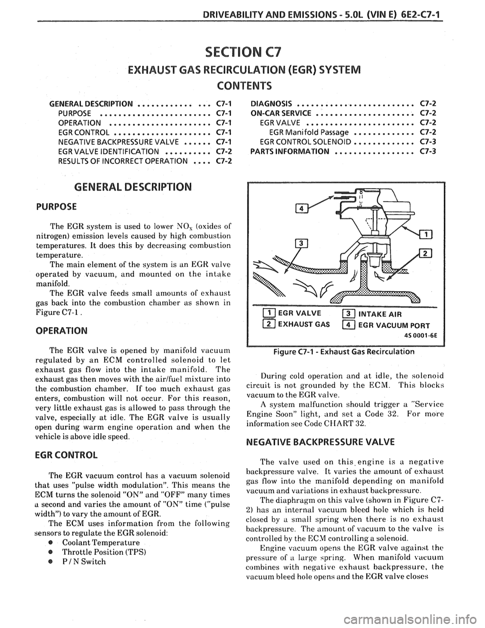
EGR valve
operated by vacuum, and mounted on the intake
manifold. The EGR valve feeds small amounts of exhaust
gas back into the combustion chamber as shown in
Figure C7-1
.
OPERATION
The EGR valve is opened by manifold vacuum
regulated by an ECM controlled solenoid to let
exhaust gas flow into the intake manifold. The
exhaust gas then moves with the
airlfuel mixture into
the combustion chamber.
If too much exhaust gas
enters, combustion will not occur. For this reason,
very little exhaust gas is allowed to pass through the
valve, especially at idle. The EGR valve is usually
open during warm engine operation and when the
vehicle is above idle speed.
EGR CONTROL
The EGR vacuum control has a vacuum solenoid
that uses "pulse width modulation". This means the
ECM turns the solenoid "ON" and "OFF" many times
a second and varies the amount of "ON" time ("pulse
width") to vary the amount of EGR.
The ECM uses information from the following
sensors to regulate the EGR solenoid:
@ Coolant Temperature
@ Throttle Position (TPS)
PIN Switch
T'IT] EGR VALVE a INTAKE AIR
EXHAUST GAS
a EGR VACUUM PORT
45 0001 -6E
Figure C7-1 - Exhaust Gas Recirculation
During cold operation and at idle, the solenoid
circuit is not grounded by the ECM.
'I'his blocks
vacuum to the EGR valve.
A system malfunction should trigger a "Service
Engine Soon" light, and set a Code
32. For more
information see Code
CHAR'I' 32.
NEGATIVE BACKPRESSURE VALVE
The valve used on this,engine is a negative
backpressure valve. It varies the amount of eshaust
gas flow into the manifold depending on manifold
vacuum and variations in exhaust backpressure.
The diaphragm on this valve (shown in Figure
C7-
2) has an internal vacuum bleed hole which is held
closed by a sinall spring when there is no eshaust
backpressure.
The amount of vacuum to the valve is
controlled
by the ECM controlling a solenoid.
Engine vacuum opens the EGR valve against
the
pressure of a large spring. When manifold vacuum
combines with negative exhaust backpressure, the
vacuum bleed hole opens and the EGR valve closes
Page 623 of 1825
6E2-C7-4 DRIVEABILITY AND EMISSIONS - 5.OL (VIN E)
TO EGR VALVE
EGR SOLENOID
CHART C-7
EXHAUST GAS RECIRULATIOM (EGR) CHECK
5.QL (VIN E) "F" "SERIES (TBI)
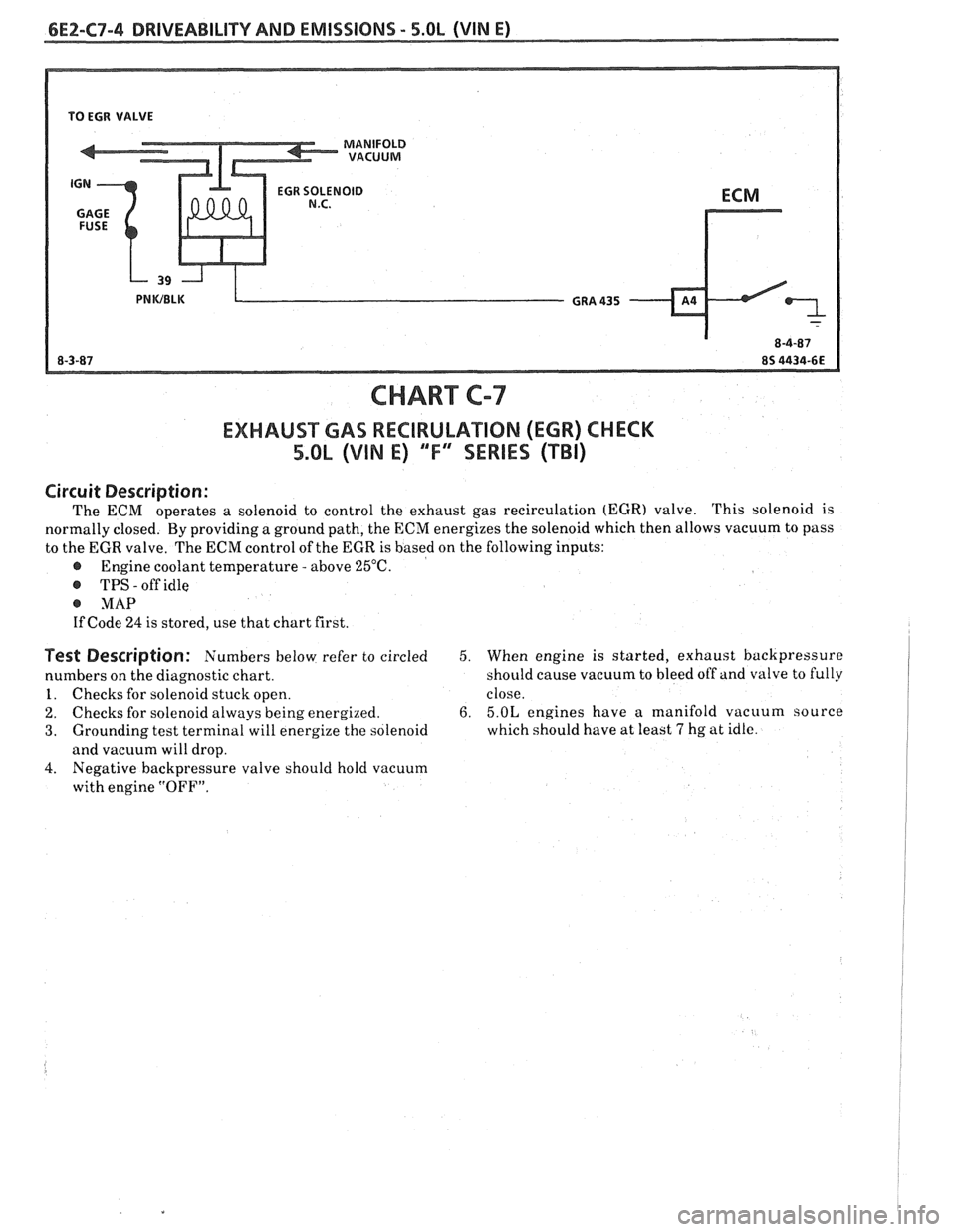
Circuit Description :
The ECM operates a solenoid to control the exhaust gas recirculation (EGR) valve. This
solenoid is
normally closed. By providing a ground path, the ECN energizes the solenoid which then allows vacuum to pass
to the EGR valve. The
ECM control of the EGR is based on the following inputs:
@ Engine coolant temperature - above 25°C.
@ TPS - off idle
@ MAP
If Code 24 is stored, use that chart first.
Test Description: Numbers below refer to circled
numbers on the diagnostic chart.
1. Checks for solenoid stuck open.
2. Checks for solenoid always being energized.
3. Grounding test terminal will energize the solenoid
and vacuum will drop.
4. Negative backpressure valve should hold vacuum
with engine
"OFF".
5. When engine is started, exhaust backpressure
should cause vacuum to bleed off and valve to fully
close.
6. 5.OL engines have a manifold vacuum source
which should have at least
7 hg at idle.
Page 626 of 1825
DRIVEABILITY AND EMISSIONS - 5.0L (VIM E) 6E2-C8-1
SECTION C8
"FRANSMISSIBN CONVERnEW CLUTCH (TCC) SYSTEM
CONTENTS
GENERAL DESCRIPTION ............... C8-1 RESULTS OF INCORRECT TCC
PURPOSE
........................ C8-1 OPERATION ..................... C8-2
......................... OPERATION ...................... C8-1 DIAGNOSIS CS-2
.................... CIRCUIT DESCRIPTION ....e.e..eea..e C8-1 ON-CAR SERVICE C8-2
................. PARTS INFORMATION C8-2
GENERAL DESCRIPTION
PURPOSE
The transmission converter clutch (TCC) system
is designed to eliminate power loss by the converter
(slippage) thus increasing fuel economy. By locking
the converter clutch,
a more effective coupling to the
flywheel is achieved. The converter clutch is operated
by an ECM controlled solenoid.
OPERATION
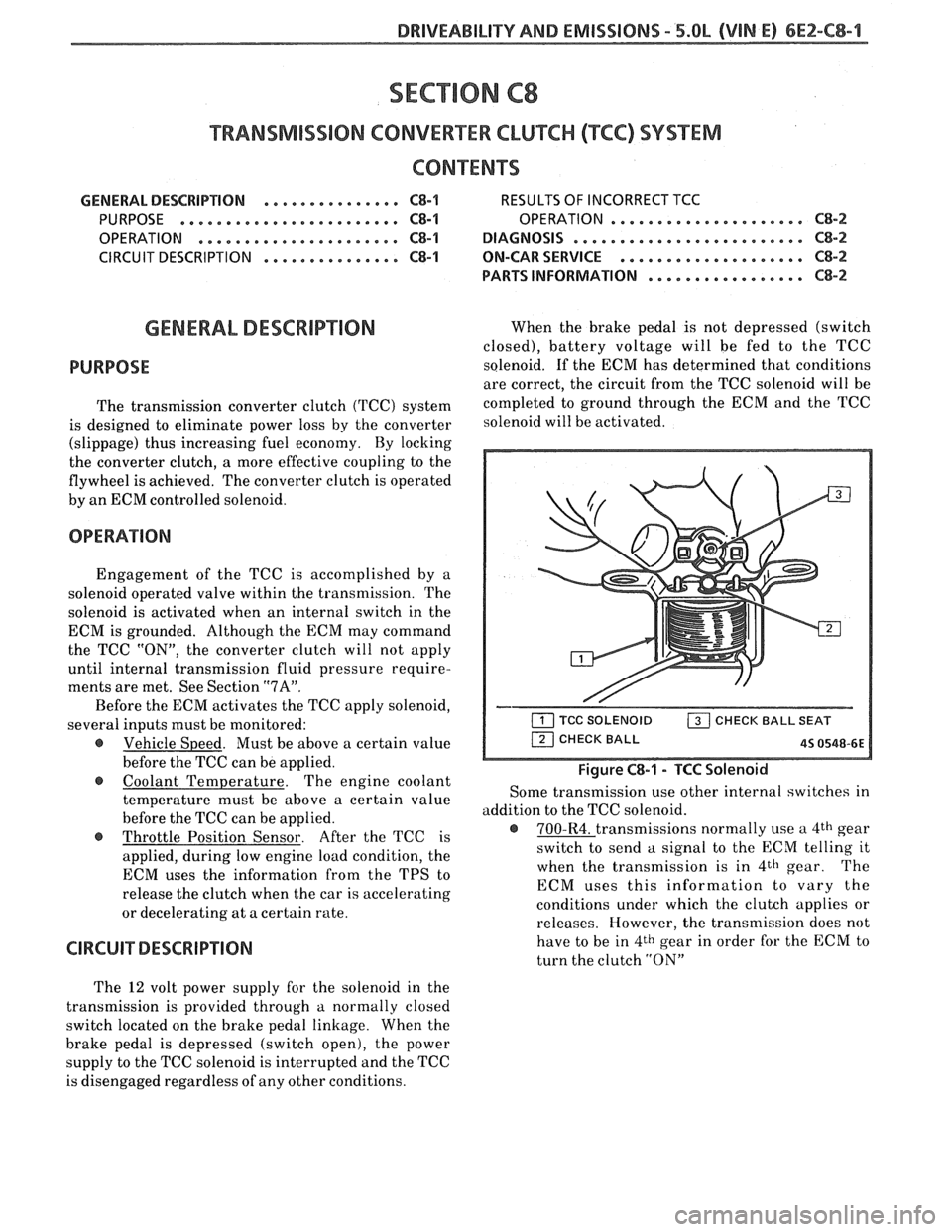
Engagement of the TCC is accomplished by a
solenoid operated valve within the transmission. The
solenoid is activated when an internal switch in the
ECM is grounded. Although the ECM may command
the TCC
"ON", the converter clutch will not apply
until internal transmission fluid pressure require-
ments are met. See Section
"7A".
Before the ECM activates the TCC apply solenoid,
several inputs must be monitored:
e Vehicle Speed. Must be above a certain value
before the TCC can be applied.
Coolant Temperature. The engine coolant
temperature must be above a certain value
before the TCC can be applied.
@ Throttle Position Sensor. After the TCC is
applied, during low engine load condition, the
ECM uses the information from the TPS to
release the clutch when the car is accelerating
or decelerating at a certain rate.
CIRCUIT DESCRIPTION
When the brake pedal is not depressed (switch
closed), battery voltage will be fed to the TCC
solenoid. If the ECM has determined that conditions
are correct, the circuit from the TCC solenoid will be
completed to ground through the ECM and the TCC
solenoid will be activated.
Figure C8-1 - TCC Solenoid
Some transmission use other internal switches in
addition to the TCC solenoid.
@ 700-R4. transmissions normally use a 4th gear
switch to send
a signal to the ECM telling it
when the transmission is in
4th gear. The
ECM uses this information to vary the
conditions under which the clutch applies or
releases. However, the transmission does not
have to be in
4th gear in order for the ECM to
turn the clutch
"ON"
The 12 volt power supply for the solenoid in the
transmission is provided through
a normally closed
switch located on the brake pedal linkage. When the
brake pedal is depressed (switch open), the power
supply to the TCC solenoid is interrupted and the TCC
is disengaged regardless of any other conditions.