coolant PONTIAC FIERO 1988 Service Manual Online
[x] Cancel search | Manufacturer: PONTIAC, Model Year: 1988, Model line: FIERO, Model: PONTIAC FIERO 1988Pages: 1825, PDF Size: 99.44 MB
Page 711 of 1825
6E3-B-2 2.8L (VIN 5) DRIVEABILITY AND EMISSIONS
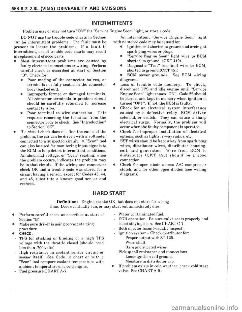
Problem may or may not turn "ON" the "Service Engine SoonJ' light, or store a code.
DO NOT use the trouble code charts in Section
"A" for intermittent problems. The fault must be
present to locate the problem. If a fault is
intermittent, use of trouble code charts may result
in replacement of good parts.
@ Most intermittent problems are caused by
faulty electrical connections or wiring. Perform
careful check as described at start of Section
"B". Check for:
@ Poor mating of the connector halves, or
terminals not fully seated in the connector
body (backed out).
@ Improperly formed or damaged terminals.
All connector terminals in problem circuit
should be carefully reformed to increase
contact tension.
@ Poor terminal to wire connection. This
requires removing the terminal from the
connector body to check. See "Introduction"
to Section
"6E".
@ If a visual check does not find the cause of the
problem, the car can be driven with a voltmeter
connected to a suspected circuit. A "Scan" tool
can also be used for monitoring input signals to
the ECM to help detect intermittent conditions.
An abnormal voltage, or "Scan" reading, when
the problem occurs, indicates the problem may
be in that circuit. If the wiring and connectors
check OK and a trouble code was stored for a
circuit having a sensor, except for Codes
43, 44,
and 45, substitute a known good sensor and
recheck. An
intermittent "Service Engine Soon" light
with no stored code may be caused by:
@ Ignition coil shorted to ground and arcing at
spark plug wires or plugs.
@ "Service Engine Soon" light wire to ECM
shorted to ground. (CKT 419).
@ Diagnostic "Test" terminal wire to ECM,
shorted to
ground.(CKT 451)
@ ECM power grounds. See ECM wiring
diagrams.
@ Loss of trouble code memory. To check,
disconnect TPS and idle engine until "Service
Engine Soon" light comes "ON". Code
22 should
be stored, and kept in memory when ignition is
turned "OFF". If not, the ECM is faulty.
@ Check for an electrical system interference
caused by a defective relay, ECM driven
solenoid, or switch. They can cause
a sharp
electrical surge. Normally, the problem will
occur when the faulty component is operated.
@ Check for improper installation of electrical
options, such as lights, 2-way radios, etc.
@ EST wires should be kept away from spark plug
wires, distributor wires, distributor housing,
coil, and generator. Wire from ECM to
distributor (CKT
453) should be a good
connection.
@ Check for open diode across A/C compressor
clutch, and for other open diodes (see wiring
diagrams).
HARD START
Definition: Engine cranks OK, but does not start for a long
time. Does eventually run, or may start hut immediately dies.
@ Perform careful check as described at start of -
Section "B".
@ Make sure driver is using correct starting
procedure.
@ CHECK:
- TPS for sticking or binding or a high TPS
voltage with the throttle closed (should read
less than
,700 volts).
- High resistance in coolant sensor circuit or
sensor itself. See Code 15 chart or with
a.
"Scan" tool compare coolant temperature with
ambient temperature on
a cold engine. 8
- Fuel pressure CHART A-7. Water contaminated
fuel.
EGR operation. Be sure valve seats properly and
is not staying open. See CHART C-7.
Both injector fuses (visually inspect).
Ignition system
- Check distributor for:
Proper output with ST-125.
Worn shaft.
Bare and shorted wires.
Pickup coil resistance and connections.
Loose ignition coil ground.
Moisture in distributor cap.
If problem exists in cold weather, check cold start
valve. See CHART A-9.
Page 713 of 1825
&E3-B-4 %.8L (VIN S) DRIVEABILITY AND EMISSIONS
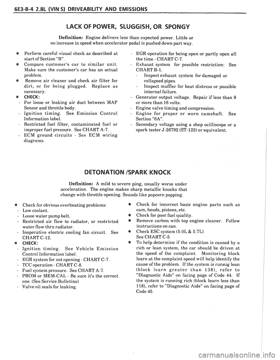
LACK OF POWER, SLUGGISH, OR SPONGY
Definition: Engine delivers less than expected power. Little or
no increase in speed when accelerator pedal is pushed down part way.
Perform careful visual check as described at
- EGR operation for being open or partly open all
start of Section
"B". the time - CHART C-7.
e Compare customer's car to similar unit. - Exhaust system for possible restriction: See
Make sure the customer's car has an actual CHART
B-1,
problem.
@ Remove air cleaner and check air filter for
dirt, or for being plugged. Replace as
necessary.
@ CHECK:
- For loose or leaking air duct between MAF
Sensor and throttle body.
- Ignition timing. See Emission Control
Information label.
- Restricted fuel filter, contaminated fuel or
improper fuel pressure. See CHART A-7.
- ECM ground circuits - See ECM wiring
diagrams.
- Inspect exhaust system for damaged or
collapsed pipes.
- Inspect muffler for heat distress or possible
internal failure.
- Generator output voltage. Repair if less than 9
or more than 16 volts.
- Engine valve timing and compression.
- Engine for proper or worn camshaft. See
Section
"6A".
- Secondary voltage using a shop ocilliscope or a
spark tester
5-26792 (ST-125) or equivalent.
DETONATION ISPARK KNOCK
Definition: A mild to severe ping, usually worse under
acceleration. The engine makes sharp metallic knocks that
change with throttle opening. Sounds like popcorn popping.
@ Check for obvious overheating problems:
- Low coolant.
- Loose water pump belt.
- Restricted air flow to radiator, or restricted
water flow thru radiator.
- Inoperative electric cooling fan circuit. See
CHART C-12.
@ CHECK:
- Ignition timing. See Vehicle Emission
Control Information label.
- EGR system for not opening - CHART C-7.
- TCC operation - CHART C-8.
- Fuel system pressure. See CHART A-7.
- PROM or MEM-CAL - Be sure it's the correct
one. (See Service Bulletins)
- Valve oil seals for leaking.
@ Check for incorrect basic engine parts such as
cam, heads, pistons, etc.
@ Check for poor fuel quality.
@ Remove carbon with top engine cleaner. Follow
instructions on can.
@ Check ESC system (5.OL & 5.7L)
See CHART C-5
o To help determine if the condition is caused by a
rich or lean system, the car should be driven at
the speed of the complaint.
Monitoring block
learn at the complaint speed will help identify the
cause of the problem.
If the system is runnig lean
(block learn greater than
1381, refer to
"Diagnostic Aids" on facing page of Code 44.
If
the system is running rich (block learn less than
l18), refer to "Diagnostic Aids" on facing page of
Code 45.
Page 715 of 1825
6E3-B-6 2.8L (VIN 5) DRIVEABILITY AND EMISSIONS
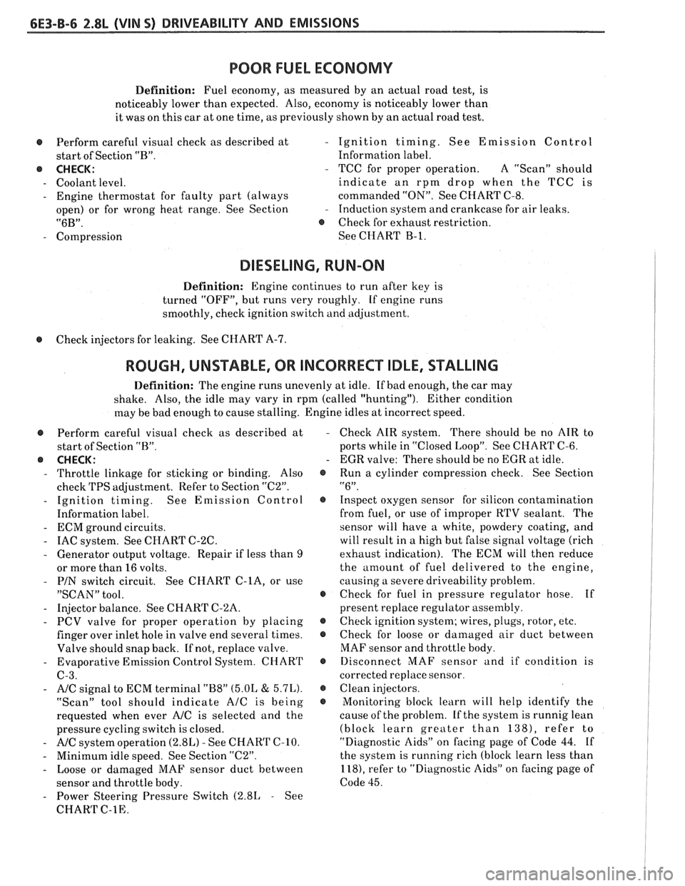
POOR FUEL ECONOMY
Definition: Fuel economy, as measured by an actual road test, is
noticeably lower than expected. Also, economy is noticeably lower than
it was on this car at one time, as previously shown by an actual road test.
@ Perform careful visual check as described at
start of Section "B".
8 CHECK:
- Coolant level.
- Engine thermostat for faulty part (always
open) or for wrong heat range. See Section
"6B".
- Compression
- Ignition timing. See Emission Control
Information label.
- TCC for proper operation. A "ScanJ' should
indicate an rpm drop when the TCC is
commanded "ON". See CHART C-8.
- Induction system and crankcase for air leaks.
8 Check for exhaust restriction.
See CHART
B-1.
DIESELING, RUN-ON
Definition: Engine continues to run after key is
turned "OFF", but runs very roughly. If engine runs
smoothly, check ignition switch and adjustment.
8 Check injectors for leaking. See CHART A-7.
ROUGH, UNSTABLE, OR INCORRECT IDLE, STALLING
Definition: The engine runs unevenly at idle. If bad enough, the car may
shake. Also, the idle may vary in rpm (called "hunting"). Either
condition
may be bad enough to cause stalling. Engine idles at incorrect speed.
@ Perform careful visual check as described at
start of Section "B".
@ CHECK:
- Throttle linkage for sticking or binding. Also
check TPS adjustment. Refer to Section
"C2".
- Ignition timing. See Emission Control
Information label.
- ECM ground circuits.
- IAC system. See CHART C-2C.
- Generator output voltage. Repair if less than 9
or more than 16 volts.
- PIN switch circuit. See CHART C-lA, or use
"SCAN" tool.
- Injector balance. See CHART C-'LA.
- PCV valve for proper operation by placing
finger over inlet hole in valve end several times.
Valve should snap back. If not, replace valve.
- Evaporative Emission Control System. CHART
C-3.
- A/C signal to ECM terminal "B8" (5.OL & 5.7L).
"Scan" tool should indicate AIC is being
requested when ever
A/C is selected and the
pressure cycling switch is closed.
- A/C system operation (2.8L) - See CHAR'l' (2-10.
- Minimum idle speed. See Section "C2".
- Loose or damaged MAF sensor duct between
sensor and throttle body.
- Power Steering Pressure Switch (2.81, - See
CHART
C-1E.
Check AIR system. There should be no AIR to
ports while in "Closed Loop". See CHART C-6.
EGR valve: There should be no EGR at idle.
Run a cylinder compression check. See Section
"6". Inspect oxygen sensor for silicon contamination
from fuel, or use of improper RTV sealant. The
sensor will have a white, powdery coating, and
will result in a high but false signal voltage (rich
exhaust indication). The ECM will then reduce
the
amount of fuel delivered to the engine,
causing a severe driveability problem.
Check for fuel in pressure regulator hose. If
present replace regulator assembly.
Check ignition system; wires, plugs, rotor, etc.
Check for loose or damaged air duct between
MAF sensor and throttle body.
Ilisconnect MAF sensor and if condition is
corrected replace sensor.
Clean injectors.
Monitoring block learn will help identify the
cause of the problem. If the system is runnig lean
(block learn greater than
138), refer to
"Diagnostic Aids" on facing page of Code
44. If
the system is running rich (block learn less than
118), refer to "Diagnostic Aids'' on facing page of
Code 45.
Page 716 of 1825
DRIVEABILITY AND EMISSIONS 2.8L (VIN S) 6E3-B-7
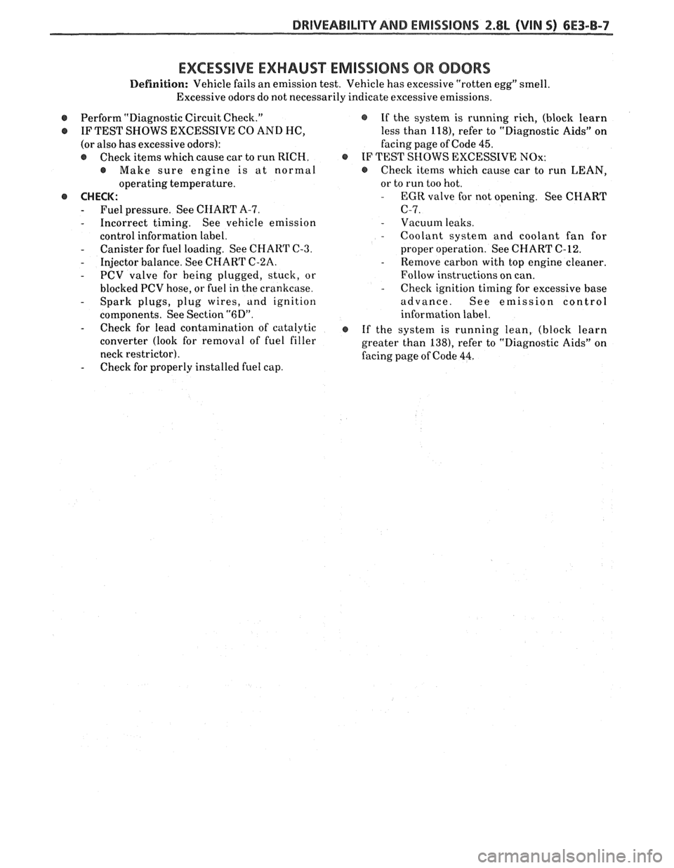
EXCESSIVE EXHAUST EMISSIONS 08 ODORS
Definition: Vehicle fails an emission test. Vehicle has excessive "rotten egg" smell.
Excessive odors do not necessarily indicate excessive emissions.
r Perform "Diagnostic Circuit Check."
e IF TEST SHOWS EXCESSIVE CO AND HC,
(or also has excessive odors):
@ Check items which cause car to run RICH.
@ Make sure engine is at normal
operating temperature.
@ CHECK:
- Fuel pressure. See CHART A-7.
- Incorrect timing. See vehicle emission
control information label.
- Canister for fuel loading. See CHART C-3.
- Injector balance. See CHART C-2A.
- PCV valve for being plugged, stuck, or
blocked PCV hose, or fuel in the crankcase.
- Spark plugs, plug wires, and ignition
components. See Section
"6D".
- Check for lead contamination of catalytic
converter (look for removal of fuel filler
neck restrictor).
- Check for properly installed fuel cap.
@ If the system is running rich, (block learn
less than
118), refer to "Diagnostic Aids" on
facing page of Code
45.
e IF TEST SHOWS EXCESSIVE NOx:
e Check items which cause car to run LEAN,
or to run too hot.
- EGR valve for not opening. See CHART
C-7.
- Vacuum leaks. - Coolant system and coolant fan for
proper operation. See CHART C-12.
- Remove carbon with top engine cleaner.
Follow instructions on can.
- Check ignition timing for excessive base
advance. See emission control
information label.
@ If the system is running lean, (block learn
greater than
138), refer to "Diagnostic Aids" on
facing page of Code
44.
Page 720 of 1825
DRIVEABILITY AND EMISSIONS 2.8L WIN S) 6E3-C1-1
SECTION C1
ELECTRONIC CONTROL MODULE (ECM) AND SENSORS
CONTENTS
GENERAL DESCRIPTION ................ C1-1 MAF Sensor ..................... C1-5
ELECTRONIC CONTROL MODULE (ECM) , . C1-1 MAT Sensor ..................... C1-5
ECMTYPES.. ...................... C1-I O2 Sensor ....................... C1-5
PROM ........................... C1-1 TPS............................ C1-5
CALPAK .......................... C1-2 VSS ........................... C1-5
ECM Function..
.................. C1-2 PIN Switch ...................... C1-5
INFORMATION SENSORS ............. C1-2 A/C Request Signal ................ C1-5
........ Engine Coolant Temp. Sensor C1-2 Power Steering Pressure Switch ...... C1-5
Mass Air Flow (MAF) Sensor ......... C1-2 Reference Signal ................. C1-5
A/C MAF Sensor .................. C1-2 ON-CAR SERVICE ..................... C1-5
..... Manifold Air Temp. (MAT) Sensor C1-2 ELECTRONIC CONTROL MODULE (ECM) . . C1-5
Oxygen (Oz) Sensor ............... C1-3 ECM & COMPONENTS REPLACEMENT
........ Throttle Position Sensor (TPS) C1-3 PROMORECM ..................... C1-6
Vehicle Speed Sensor
.............. C1-3 Functional Check ................. C1-7
...... ParkINeutral Switch (Auto Only) C1-4 CALPAK.......................... C1-7
AIC "ON" Signal .................. C1-4 COOLANTSENSOR .................. C1-7
Distributor Reference Signal
......... C1-4 MAFSENSOR ...................... C1-7
DIAGNOSIS ......................... C1-4 MAF SENSOR POWER & BURN-OFF RELAY. C1-7
ECM .......e.........e........... C1-4 OXYGENSENSOR ................... C1-8
PROM ........................... C1-4 Throttle Position Sensor ............ C1-8
ECM Inputs..
.................... C1-5 PARKJNEUTRALSWITCH .............. C1-9
Coolant Temp. Sensor ............. C1-5 PARTS INFORMATION ................. C1-9
GENERAL DESCRIPTION
ELECTRONIC CONTROL MODULE (ECM)
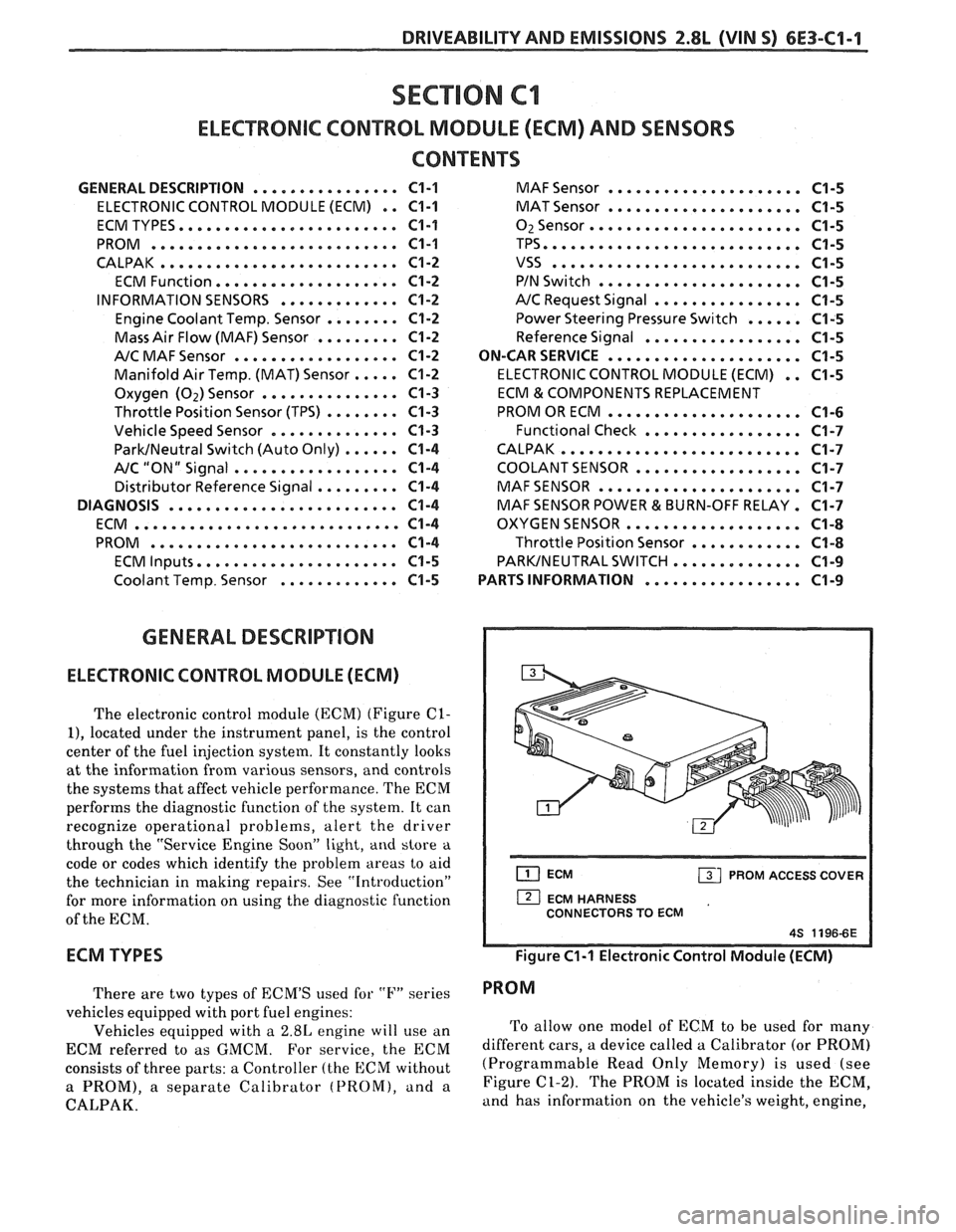
The electronic control module (ECM) (Figure C1-
I), located under the instrument panel, is the control
center of the fuel injection system. It constantly looks
at the information from various sensors, and controls
the systems that affect vehicle performance. The ECM
performs the diagnostic function of the system. It can
recognize operational problems, alert the driver
through the "Service Engine Soon"
light, and store a
code or codes which identify the problem areas to aid
the technician in making repairs. See "Introduction"
for more information on using the diagnostic function
of the ECM.
ECM TYPES
There are two types of ECM'S used for "I?" series
vehicles equipped with port fuel engines:
Vehicles equipped with a
2.8L engine will use an
ECM referred to as GMCM. For
service, the ECM
consists of three parts: a Controller (the ECM without
a PROM), a separate Calibrator (PROM), and a
CALPAK.
ECM PROM ACCESS COVER I
1 ECM HARNESS
CONNECTORS TO ECM
Figure C1-1 Electronic Control Module (ECM)
PROM
To allow one model of ECM to be used for many
different cars, a device called a Calibrator (or PROM)
(Programmable Read Only Memory) is used (see
Figure
C1-2). The PROM is located inside the ECM,
and has information on the vehicle's weight, engine,
Page 721 of 1825
6E3-C1-2 2.8L (VIN S) DRIVEABILITY AND EMISSIONS
transmission, axle ratio, and several others. While one
ECM part number can be used by many car lines, a
PROM is very specific and must be used for the right
car. For this reason, it is very important to check the
latest parts book and Service Bulletin information for
the correct part number when replacing a PROM.
An ECM used for service (called a controller)
comes without a PROM. The PROM from the old ECM
must be carefully removed and installed in the new
ECM (see On-Car Service).
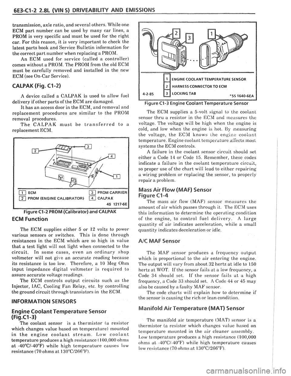
CALPAK (Fig. C1-2)
A device called a CALPAK is used to allow fuel
delivery if other parts of the ECM are damaged.
It has an access door in the ECM, and removal and
replacement procedures are similar to the PROM
removal procedures.
The CALPAK must be transferred to a
replacement ECM.
M (ENGINE CALIBRATOR)
Figure C1-2 PROM (Calibrator) and CALPAK
ECM Function
The ECM supplies either 5 or 12 volts to power
various sensors or switches. This is done through
resistances in the ECM which are so high in value
that
a test light will not light when connected to the
circuit. In some cases, even an ordinary shop
voltmeter will not give an accurate reading because
its resistance is too low. Therefore, a 10
Meg Ohm
input impedance digital voltmeter is required to
assure accurate voltage readings.
The ECM controls output circuits such as the
Injector, IAC, Cooling Fan Relay, etc. by controlling
the ground circuit
thr0ug.h transistors in the ECM.
Engine Coolant Temperature Sensor
(Fig.CI-3)
The coolant sensor is a thermistor (a resistor
which changes value based on temperature) mounted
in the engine coolant stream.
Low coolant
temperature produces a high resistance
( 100,000 ohms
at -40°C/-40°F) while high temperature causes low
resistance (70 ohms at
130"C/26fi°F).
ENGINE COOLANT TEMPERATURE SENIOR
HARNESS CONNECTOR TO ECM
4-2-85 LOCKING TAB *5S 4640-6EA
Figure C1-3 Engine Coolant Temperature Sensor
The ECM supplies a 5-volt signal to the coolant
sensor thru a resistor in the ECM
and measures thc
voltage. The voltage will be high when the engine is
cold, and
low when the engine is hot. t3y measuring
the voltage, the ECM knows
the engiao coo/ant
temperature. Engine coolant temperature aifeces most
systems the ECM controls.
A failure
in the coolant sensor circuit should set
either a Code 14 or Code 15. Remember, these codes
indicate a failure in the coolant temperature circuit,
so proper use of the chart will
lead to either repairing
a wiring problem or replacing the sensor, to properly
repair a problem.
Mass Air F10w (MAF) Sensor
Figure C1-4
The mass air flow (MAF) sensor measures the
amount of air which passes through it.
'I'he ECM uses
this information to determine the operating condition
of the engine, to control
fuel delivery. A large
quantity of air indicates acceleration, while a small
quantity indicates deceleration or idle.
NC MAF Sensor
'I'he MAF sensor produces a frequency output
which is proportional to the air entering the en,'
alne.
The output will vary from about 32 hertz at idle to 150
hertz at WOT. If the sensor fails at a low frequency, a
Code 34 should set. If the sensor fails at a high
frequency, a
Code 33 should set. A Code 44 or 45 may
also be caused by a faulty
MAF sensor.
'I'he code charts will explain how to determine if
the sensor is causing the rich or lean condition.
Manifold Air Temperature (MAT) Sensor
The manifold air temperature (MAT) sensor is a
thermistor
(a resistor which changes value based on
temperature mounted in the
air cleaner assembly.
1,ow temperature produces a high resistance (100,000
ohms at -40°C/-400F) while high temperature causes
low resistance (70 ohms at
130"C/2G6"F).
Page 724 of 1825
DRIVEABILITY AND EMlSSlQNS 2.8L (VIN S) 6E3-C1-5
ECM Inputs
All of the sensors and input switches can be
diagnosed by the use of a "Scan" tool. Following is a
short description of how the sensors and switches can
be diagnosed by the use of "Scan".
The "Scan" can
also be used to compare the values for a normal
running engine with the engine you're diagnosing.
Coolant Temperature Sensor
A "Scan" tool displays engine temperature in
degrees centigrade. After
engine is started, the
temperature should rise steadily to about 90°C then
stabilize when thermostat opens. If the engine has not
been run for several hours (overnight) the coolant
temperature and MAT temperatures should read close
to each other. A fault in the coolant sensor circuit
should set a Code
14 or 15. The code charts also
contain a chart to check for sensor resistance values
relative to temperature.
MAF Sensor
A "Scan" tool reads the MAF value and displays it
in grams per second. Should read between 4-7 on a
fully warmed up idling engine. Values should change
rather quickly on acceleration, but values should
remain fairly stable at any given RPM. Most "Scan"
tools will have 2 positions for reading
MAE' sensor
values. (MAF
& Air Flow). Both values should read
the same if no Code 33 or 34 is set, but if a code is set,
the MAF values will be the default value and the Air
Flow parameter will lock in on the value to which the
ECM recognized the fault. A failure in the MAF
sensor or circuit should set a Code 33 or 34.
MAT Sensor
A "Scan" tool displays temperature of the air
entering the engine and should read close to ambient
air temperature when engine is cold, and rise as
underhood temperature increases. If the engine has
not been run for several hours (overnight) the MAT
sensor temperature and coolant temperature should
read close to each other. A failure in the MAT sensor
circuit should set
a Code 23 or 25. The code charts also
contain a chart to check for sensor resistance values
relative to temperature.
02 Sensor
The "Scan" has several positions that will indicate
the state of the exhaust gases,
O1! voltage, integrator,
and block learn. See "Scan" position information in
"Introduction," Section
"6E".
A problem in the O2 sensor circuit, or fuel system,
should set a Code 13 (open circuit), Code 44 (lean
indication), Code 45 (rich indication). Refer to
applicable chart if any of these codes
were stored in
memory.
TPS
A "Scan" tool displays throttle position in volts.
You should read
.55V f .08V, with throttle closed and
ignition on, or at idle. Voltage should increase at
a
steady rate as throttle is moved toward WOT.
The ECM has the ability to Auto-Zero the TPS
voltage if it is below about .7V (700
mV). This means
that any voltage less than
.7 volts will be determined
by the ECM to be
0% throttle. A failure in the TPS or
circuit should set a Code 21 or 22.
A "Scan" tools reading should closely match with
speedometer reading with drive wheels turning.
A
failure in the VSS circuit should set a Code 24.
PIN Switch
A "Scan" tool should read PIN when in Park, or
Neutral, and R-D, L, when in Drive or Overdrive.
This reading may vary with different makes of tools.
Refer to CHART
C-1A for PIN switch diagnosis.
NC Request Signal
"Scan" tool should indicate A/C request "ON,"
when A/C is requested and the pressure cycling switch
is closed.
Power Steering Pressure Switch
A "Scan" tool should read "OFF" normally and
"ON" with high pressure. This reading may vary with
different make of tools. Refer to CHART
C-1E for
PSPS diagnosis.
Reference Signal
A "ScanJ' tool will read this signal and is displayed
in rpm.
ON-CAR SERVICE
ELECTRONIC CONTROL MODULE (ECM)
Service of the ECM should normally consist of
either replacement of the ECM or a PROM change.
If the diagnostic
procedures call for the ECM to be
replaced, the engine calibrator (PROM) and ECM
should be checked first to see if they are the correct
parts. If they are, remove the PROM from the faulty
ECM
and install it in the new service ECM. THE
SERVICE ECM WILL NOT CONTAIN A PROM or
CALPAK. Trouble Code 51 indicates the PROM is
installed improperly or has malfunctioned. When
Code
51 is obtained, check the PROM installation for
bent pins or pins not fully seated in the socket. If it is
installed correctly and Code 51 still shows, replace the
PROM.
Page 726 of 1825
DRIVEABILITY AND EMISSIONS 2.8L (VIN S) 6E3-C1-7
REFERENCE END
PROM PROM CARRIER
4S 81165-6E
Figure C1-8 PROM in PROM Carrier
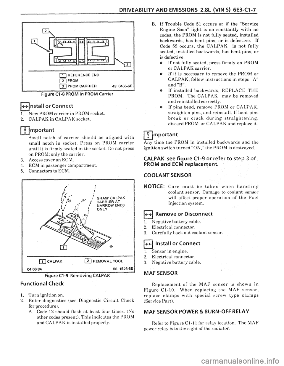
mnstall or Connect
1. New PROM carrier in PROM socliet.
2. CALPAK in CALPAK socket.
mmportant
Small notch of carrier shoiild he aligned with
small notch in socket. Press on PROM carrier
until it is firmly seated in the socket. Do not press
on PROM; only the carrier.
3. Access cover on ECM.
4. ECRil in passenger compartment.
5. Connectors to ECM.
b A,' I
;,* fd I
: GRASP CALPAK 1% ,/w 1' CARRIERAT
[ZJ REMOVAL TOOL
Figure C1-9 Removing CALPAK
B. If Trouble Code 51 occurs or if the "Service
Engine Soon" light is on constantly with no
codes, the PROM is not fully seated, installed
backwards, has bent pins, or is defective. If
Code
52 occurs, the CALPAK is not fully
seated, installed backwards, has bent pins, or
is defective.
If not fully seated,
press firmly on PROM
or CALPAK carrier
a, If it is necessary to remove the PROM or
CALPAK, follow instructions in steps "A"
and
"B".
@ If installed backwards, REPLACE THE
PROM. The CALPAK may be removed
and reinstalled correctly.
@ If pins bend, remove PROM or CALPAK,
straighten pins, and reinstall. If
bent pins
break or crack during
straightening,
discard PROM or CtILPAK and replace it,.
am port ant
Any time the PROM in installed backwards and the
ignition switch turned
"ON," the f'I
PROM and ECM replacement.
COOLANT SENSOR
NOTICE:
Care must be taken when handling
coolant sensor.
Damage to coolant sensor
will affect proper operation of the Fuel
Injection
system.
B Remove or Disconnect
1. Negative buttery cable.
2.
Electricril connector.
3. Carefully back out coolant sensor.
a ln,aIl
1. Sensor in
or Connect
engine.
2. Electrical connector.
3. Negative battery cable.
MAF SENSOR
Functional Check
Replacement of the iL'IAF xcnsor is shown in
Figure C1-10. When
replacing the MAF sensor,
1. Turn ignition on.
replace cla~llps with special hcrew type cla~rlps
2. Enter diagnostics (see Diagnostic Circuit Check (Service Part).
for procedure).
A. Code 12 should flash at least four times. (Yo MAF SENSOR POWER & BURN-OFF RELAY
other codes present). This indicates the PIIOM
and CALPAK is installed properly.
Refer to Figure C 1- 1 1 for relay location. 'rhe MAF
power relay is to the right ofthe radiator
Page 728 of 1825
DRIVEABILITY AND EMISSIONS 2.8L (VIN 5) 6E3-C1-9
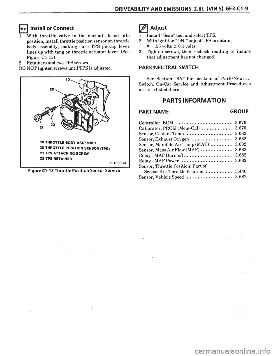
Install or Connect
1. With throttle valve in the normal closed idle
position, install throttle position sensor on throttle
body assembly, making sure TPS pickup lever
lines up with tang on throttle actuator lever. (See
Figure
C1-13)
2. Retainers and two TPS screws.
DO NOT tighten screws until TPS is adjusted.
10 THROTTLE BODY ASSEMBLY
20 THROTTLE POSITION SENSOR (TPS)
21 TPS ATTACHING SCREW
22 TPS RETAINER
55 1638-6E
Figure C1-13 Throttle Position Sensor Service
Adjust
1. Install "Scan" tool and select TPS.
2. With ignition "ON," adjust TPS to obtain;
@ .55 volts + 0.1 volts
3. Tighten screws, then recheck reading to insure
that adjustment has not changed.
PARKINEUTRAL SWITCH
See Section "$A" for location of ParkINeutral
Switch. On-Car Service and Adjustment Procedures
are also listed there.
PARTS INFORMAION
PART NAME GROUP
..................... Controller, ECM
Calibrator, PROM
(Mem-Call ............
Sensor, Coolant Temp .................
Sensor, Exhaust Oxygen ...............
Sensor, Manifold Air Temp (MAT) ........
Sensor, Mass Air Flow (MAF). ...........
Relay - MAF Burn-off.. ................
Relay - MAF Power ...................
Sensor, Throttle Position: Part of
Sensor Kit, Throttle Position
..........
Sensor, Vehicle Speed .................
Page 736 of 1825
DRIVEABILITY AND EMISSIONS 2.8b (VIN 5) 6E3-C2-1
SECTION C2
FUEL CONTROL SYSEEIVI
CONTENTS
GENERAL DESCRIPTION . . . . . . . . . . . . . . . . C2-1 FUEL RAIL SERVICE . . . . . . . . . . . . . , . . . C2-6
PURPOSE ......................... C2-1 UNIT SERVICE PROCEDURES . . . . . . . . . . . C2-6
MODES OF OPERATION . . . . . . . . . . . . . . C2-1 COLD START TUBE & VALVE ASSEMBLY.. . C2-7
Starting Mode . . . . . . . . . . . . . . . . . . . C2-2 FUEL PRESSURE CONNECTION ASSEMBLY . C2-7
Clear Flood Mode . . . . . . . . . . . . . . . . . C2-2 FUEL BLOCK AND SEAL.. . . . . . . . . . . . . . C2-9
Run Mode .. .. . . . . . . . . . . . . . . . . . . C2-2 FUELINJECTORS .. . . . .. ... .... . . . ... C2-9
Acceleration Mode. . . . . . . . . . . . . . . . C2-2 Port Injectors wl Injector Retaining Clips C2-9
Deceleration Mode . . . . . . . . . . . . . . . C2-2 Fuel Pressure Regulator . . . . . . . . . . . . C2-10
Battery Voltage Correction Mode . . . . . C2-2 PORT INJECTORS . . . . . . . . . . . . . . . . . . . C2-10
Fuel Cutoff Mode . . . . . . . . . . . . . . . . . C2-3 PRESSURE REGULATOR.. . . . . . . . . . . . . . C2-10
Fuel Control System Components . . . . . C2-3 COLD START FUEL INJECTION SWITCH . . . C2-1 I
Basic System Operation. . . . . . . . . . . . . C2-3 THROTTLE BODY . . . . . . . . . . . . . . . . . . . C2-11
THROTTLE BODY UNIT . . . . . . . . . . . . . . . C2-3 THROTTLE BODY SERVICE IDENTIFICATION C2-11
FUEL RAIL.. . . . . . . . . . . . . . . . . . . . . . . . C2-3 MINIMUM IDLE SPEED ADJUSTMENT . . . . C2-14
FUEL INJECTOR.. . . . . . . . . . . . . . . . . . . . C2-3 UNIT REPAIR PROCEDURES . . . . . . . . . . . . C2-14
PRESSURE REGULATOR.. . . . . . . . . . . . . . C2-3 IDLE AIR CONTROL VALVE
IDLE AIR CONTROL (IAC) VALVE
. . . . . . . . C2-4 ASSEMBLY &GASKET.. . . . . . . . . . . . . . . C2-14
FUEL PUMP ELECTRICAL CIRCUIT . . . . . . . C2-4 IDLE AIRIVACUUM SIGNAL
DIAGNOSIS . . . . . . . . . . . . . . . . . . . . . . . . . C2-5 HOUSING ASSEMBLY . . . . . . . . . . . . . . . . C2-15
FUEL CONTROL SYSTEM . . . . . . . . . . . . . . C2-5 COOLANT CAVITY COVER & O-RING . . . . * C2-15
IDLE AIR CONTROL VALVE . . . . . . . . . . . . C2-5 IDLE AIR CONTROL / COOLANT
ON-CAR SERVICE . . . . . . . . . . . . . . . . . . . . . C2-5 COVERASSEMBLY .............,.... C2-16
PORT FUEL INJECTION COMPONENTS . . . . C2-5 FUEL PUMP RELAY . . . . . . . . . . . . . . . . . . C2-17
FUEL PRESSURE RELIEF PROCEDURE . . . . . C2-5 OIL PRESSURE SWITCH . . . . . . . . . . . . . . . C2-17
Plenum ........................ C2-5 PARTS INFORMATION . . . . . . . . . . . . . . . . . C2-17
Fuel Rail & Pressure Regulator Assembly . C2-5
GENERAL DESCRIPTION
PURPOSE
The basic function of the fuel control system is to
control fuel delivery to the engine.
Fuel is delivered to the engine by individual fuel
injectors mounted in the intake manifold near each
cylinder. The main control sensor is the oxygen
(02) sensor,
which is located in the exhaust manifold. The
O2
sensor tells the ECM how much oxygen is in the
exhaust gas, and the ECM changes the airlfuel ratio to
the engine by controlling the fuel injectors. The best
mixture to minimize exhaust emissions is
14.7 to 1,
which allows the catalytic converter to operate the
most efficiently. Because of the constant measuring
and adjusting of the airlfuel ratio, the fuel injection
system is called
a "Closed LoopJ' system (shown in
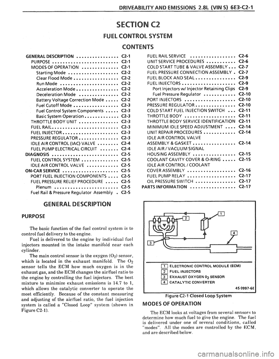
Figure C2-1).
ELECTRONIC CONTROL MODULE (ECM)
FUEL INJECTORS
EXHAUST OXYGEN
02 SENSOR
1 CATALYTIC CONVERTER
45 0997-6E
Figure C2-1 Closed Loop System
MODES OF OPERATION
The ECM looks at voltages from several sensors to
determine how much fuel to give the engine.
The fuel
is delivered under one of several conditions,
called
"modes". All the modes are controlled by the E:CM.
and are described below.