Door handle PONTIAC FIERO 1988 Service Repair Manual
[x] Cancel search | Manufacturer: PONTIAC, Model Year: 1988, Model line: FIERO, Model: PONTIAC FIERO 1988Pages: 1825, PDF Size: 99.44 MB
Page 113 of 1825
866 CHASSIS SHEET METAL
PROPER IDENTIFICATION AND CDAlrUmNG
OF INTERIOR PWSTIC TRlM
Interior plastic trim parts are normally supplied
in only one color. It is necessary to paint most parts.
Most vinyl headlinings and soft vinyl seat cushion and
hack cover assemblies are furnished in colors.
Instructions on how to identify each paintable
plastic part, and how to apply the available paint
materials are as follows:
Paintable plastic trim components, as used on
General Motors interiors, can be divided into three
general types:
@ Polypropylene Plastic
@ ABS Plastic
@ Vinyl Plastic
Excluding the soft vinyl seat cushion and seat
back trim cover assemblies, the plastic used most
widely on the interior of bodies is "POLYPROPYL-
ENE" and, as noted later, requires special refinishing
materials and procedures. Therefore, it is important
for a painter to be able to identify each plastic in order
to paint it satisfactorily. The purpose of the following
tests is to determine the identity of a given plastic so
that the proper paint procedure and refinishing mate-
rials will be used.
TEST PROCEDURE
Polypropylene, ABS or Vinyl Plastic
From a hidden backside portion of the part,
remove a sliver of plastic with a sharp blade.
Holding the sliver with needle-nose pliers, put it
to a flame and observe whether or not any
smoke is given off when burning.
ABS PLASTIC will give off a HEAVY BLACK
SMOKE, and POLYPROPYLENE will burn
clean.
However, if a sliver gives off OTHER THAN
HEAVY BLACK SMOKE, it is either DIRTY
POLYPROPYLENE OR IS VINYL. To deter-
mine which it is, the following burn test should
be made with the hot tip of a clean copper wire.
Heat the tip of the copper wire to a "red-glow"
with a propane (gas) torch.
Touch the heated wire to a hidden portion of the
plastic in question, to get some of the plastic on
the wire.
Return the wire, with its
now plastic-coated tip,
to the flame and observe for flame color.
If the flame given off from the wire is of the
GREEN-TURQUOISE-BLUE RANGE, then
the PLASTIC IS VINYL. (Any other color
flame would indicate the material is dirty poly-
propylene.
)
PAINWING lNTERiOR PWSTIC PARTS
Before painting, always check the body number
plate of the car for the
correct trim code color number
for that model year. The body number plate is located
on the upper horizontal surface of the shroud. Interior
color is color keyed to this "Trim Combination Num-
ber" (TR) on the body plate. Each paint supplier pro-
vides an interior color chart which identifies their
stock number, color name, gloss factor and trim com-
bination number for each "conventional" interior
color. Charts listing "vinyl" interior colors are also
provided.
"CONVENTIONAL" interior acrylic colors are
designed for use only on hard trim parts, such as:
1. Steel parts (primer or sealer required on new
service parts).
2. Hard POLYPROPYLENE plastic ("Special
Primer" required
- See GM Parts Catalog).
3. Hard ABS plastic (NO primer necessary).
"VINYL" interior colors are designed for soft
and/or flexible trim parts, such as instrument panel
cover pad assemblies, upper door trim pad assem-
blies, molded headlining panels, head rests and assist
handles. These colors require a final top coat of clear
vinyl spray, with instrument panel pads requiring a
"nonglare" clear final top coat. Other trim parts
require a degree of gloss to match similar adjacent
parts.
POLYPROPYLENE PUSTIC PARTS
The system for painting polypropylene parts
involves the use of a special primer. It is essential that
the service part be first primed with a coating of spe-
cial POLYPROPYLENE PRIMER (Detroit
Autobody
#PP-2250, or equivalent) according to factory recom-
mendations on the can. Because the primer acts as a
bonding agent between the plastic and acrylic lacquer, failure to use it will result in color coat "lifting"
and/or
"peeling" problems. After priming, the part can be
color coated with conventional interior acrylic
lacquer,
PROCEDURE
1. Wash part thoroughly with a cleaning solvent ("Acryli-Clean," "Prep-Sol," or equivalent) that
will not leave any greasy film.
2. Apply a thin, wet coat of the special polypropyl-
ene primer according to label directions on can.
Wetness of primer is best determined by observ-
ing gloss reflection of spray application in ade-
quate lighting. Be sure primer application
includes all edges. Allow
the primer to flash dry
ONE (1) MINUTE MINIMUM and TEN (10)
MINUTES MAXIMUM. (If the flash period
before color coating should extend beyond ten
minutes, the primer MUST be reapplied to
avoid previously mentioned adhesion
problems
.)
Page 114 of 1825
CHASSIS SHEET METAL 2@-7
3. During the above flash time period (1 to 10 min-
utes), apply appropriate "conventional" interior acrylic lacquer color as required and allow
painted part to dry for
4 to 5 hours before install-
ing on car.
RlGlD OW HARD ABS PMS"TIC PARTS
Rigid or hard ABS plastic requires no primer.
"Conventional" interior acrylic lacquers adhere satis-
factorily to hard ABS plastics.
Procedure
1. Wash part thoroughly with a cleaning solvent
(Acrylic-Clean, Pre-Kleano, Prep-Sol or equiv-
alent) to remove any dirt or grease.
2. Apply appropriate "conventional" interior
acrylic lacquer color. Apply only sufficient
color for proper hiding to avoid washout of
"grain" effect.
3. Allow to dry and then install part.
VINYL AND FLEXIBLE (Son) ABS
PLASTIC PARTS
The outer cover or skin material of "flexible"
instrument panel cover (pad) assemblies is made of an
ABSIPVC plastic blend. The same is true of many
"padded" door trim assemblies. The soft cushion pad-
ding under the I.P. skin is urethane foam plastic. The
most widely used
"flexible" vinyls (poly vinyl chlo-
ride)
are coated fabrics, such as used in seat trim,
some door trim assemblies, molded headlining panels
and sun visors. Most head rests are "flexible" vinyls.
Examples of "hard vinyls are: door and front seat
back assist handles and coat hooks.
The paint system of vinyl and flexible ABS
plastic involves the use of interior "vinyl" color and a
clear vinyl top coat.
Procedure
1. Wash part thoroughly with a vinyl cleaning and
preparation solvent ("Vinyl Press"
- Ditzler,
"Vinyl Prep Conditioner"
- Detroit Autobody
or equivalent) to remove greasy film or silicone.
Wipe off cleaner while still wet with clean,
lint-
free cloth.
2. Immediately after wiping face dry, apply inte-
rior "vinyl" color in wet coats allowing suffi-
cient flash time between coats (see label
directions on can). Use proper "vinyl" color as
designated by interior trim combinations. Apply
only sufficient color for proper hiding to avoid
washout of "grain" effect. No primer or
primer-
sealer is required.
3. Before the final vinyl color coat has dried, apply
two coats of clear vinyl top coat spray (instru-
ment panels will require the "nonglare" clear top
coat). Do not allow the first spray coat to com-
pletely dry before spraying on the second. Use
top coat with appropriate gloss level to match adjacent similar components. This
clear coat is
necessary to control the gloss requirement and
prevent
'tracking" (rubbing-off) of the color
coat after drying.
4. Allow to dry according to label directions before
installing part.
ON-VEHICLE SERVICE
CONCEALED HEADLIGHTS
The concealed headlights used on this model are
electrically operated. When the headlights are turned
on, solid state circuitry activates the actuators. This
same circuitry senses when the actuators stop moving
and removes the ground to deactivate the actuators.
When the headlights are turned off, the actuators run
in opposite direction closing the headlight doors.
Should an electrical failure occur in the head-
light circuit, they may be raised manually by rotating
the knob on the actuator in a counterclockwise direc-
tion until the headlights are fully open. The headlights
may be lowered by rotating the knob on the actuator in
a clockwise direction until the headlights are fully
closed.
For electrical circuit information and diagnosis,
refer to Section
8A of this manual.
If it is desired to raise the headlights with the
lights off, either of the following procedures may be
used:
1. Turn the lights on. After the headlights are
open, disconnect the electrical connections at
the actuator connectors. Turn the lights off. The
headlights will now remain in the open position.
2. Turn the parking lights on. Depress the head-
light rocker switch lightly. The headlights may
then be raised "up" fully with the lights off.
Adjust
Because of the number of adjustments possible
and the number of attaching points of the concealed
headlight body assembly
(9), only those attachments
which control the adjustment desired should be loos-
ened. Make one
adjbstment at a time.
NOTICE: The headlight door does NOT have
slotted mounting holes and therefore is not
adjustable by itself. This insures proper clearance
between the headlight door and the hood and
fenders in both the raised and lowered positions.
The entire headlight body assembly must be
adjusted to achieve the desired appearance and
fit. Care should be exercised when adjusting the
headlight body assembly. Severe hammer blows could damage the die cast aluminum headlight
body assembly.
TO RAISE OR LOWER the headlight body
assembly, proceed as follows:
1. Open hood.
2. Raise headlights.
Page 1695 of 1825
1 H-14 GENERAL INFORMATION - F STYLE
NOTICE: Service part must be primed with a
coating of special polypropylene primer according
to factory recommendations. Failure to use the
required primer as directed will result in color coat
lifting and/or peeling problems. Use
Polypropylene Primer, part no. 1052364, or
equivalent.
1. Wash part with a solvent such as Acryli-Clean,
Pre-Kleano, Prep-Sol or equivalent. Follow label
directions.
2. Apply
a thin, wet coat of polypropylene primer
according to label directions. Wetness of primer
is determined by observing gloss reflection of
spray application in adequate lighting. Be sure
primer application includes all edges. Allow
primer to flash dry one minute minimum and ten
minutes maximum.
3. During the above flash time period (1 to 10
minutes), apply conventional interior acrylic
lacquer color as required and allow to dry before
installing part. Application of color during above
flash time range promotes best adhesion of color
coats.
PAINTING RIGID OR HARD ABS PLASTIC
PARTS
Rigid or hard ABS plastic requires no primer.
Conventional interior acrylic lacquers adhere
satisfactorily to hard ABS plastics.
1. Wash part with a solvent such as ~cr~li-clean,
Pre-Kleano, Prep-Sol or equivalent.
2. Apply conventional interior acrylic lacquer color
according to trim combination (see paint supplier
color chart for trim and color code). Apply only
enough color for proper hiding to avoid washout
of "grain" effect.
3. Allow to dry following label directions and then
install part.
PAINTING VINYL AND FLEXIBLE (SOFT) ABS
PLASTIC PARTS
The outer cover material of flexible instrument
panel cover assemblies is made mostly of ABS plastic
modified with PVC or vinyl. The same is true of many
padded door trim assemblies. The soft cushion padding
under
ABS covers is urethane foam plastic.
The most widely used flexible vinyls (polyvinyl
chloride) are coated fabrics as used in seat trim, some
door trim assemblies, headlinings and sunshades. Most
head restraints are covered with flexible vinyls.
Examples of hard vinyls are door and front
seatback
assist handles, coat hooks and exterior molding inserts. The
paint system for vinyl and flexible
ABS
plastic involves the use of interior vinyl color and a
clear vinyl top coat, No primer or primer-sealer is
required.
1. Wash part with a vinyl cleaning and preparation
solvent, such as Vinyl Prep, Vinyl Prep
Conditioner or equivalent. Wipe off cleaner while
still wet with clean, lint-free cloth.
2. As soon as the surface has been wiped dry, apply
interior vinyl color in wet coats. Allow flash time
between coats. Follow label directions. Use
proper vinyl color as shown by interior trim code
combination. Apply only enough color for proper
hiding to avoid washout of grain effect.
3. Before color flashes completely, apply one wet
double coat of vinyl clear top coat. Use top coat
with appropriate gloss level to match adjacent
similar components. The clear coat is necessary
to control the gloss requirement and to prevent
crocking (rubbing-off) of the color coat after
drying.
4. Allow to dry according to label directions before
installing part.
AVAILABILITY OF COLORS FOR PAINTING
INTERIOR PLASTIC PARTS
Interior colors are color keyed to trim code
combination numbers located on the body number
plate or service parts identification label.
Conventional interior acrylic lacquer colors are
designed for use only on hard trim parts, such as:
1. Steel parts (primer and/or sealer required on new
service parts)
2. Hard
ABS plastic (no primer necessary)
3. Hard polypropylene plastic (special primer
required)
Each major paint supplier provides an interior
color chart which identifies the stock number, color
name, gloss factor and trim code combination number
for each conventional interior color.
Vinyl interior colors are designed for soft trim
parts such as instrument panel cover assemblies, door
trim assemblies and head restraints. These colors
require a final top coat of clear vinyl. Instrument panel
covers require a nonglare final top coat. Other trim
parts require a degree of gloss to match similar
adjacent parts. Use interior vinyl colors and clear vinyl
finishes such as Ditzler Vinyl Spray Colors, American
Jetway UR-1 Vynicolor or equivalents.
SPECIAL BODY TOOLS
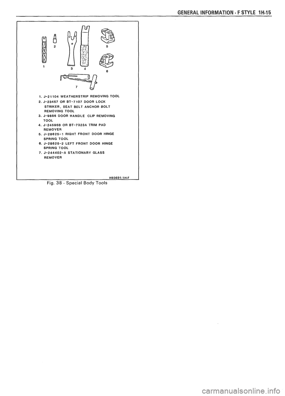
Figure 38 shows the special body tools that are
recommended as aids in servicing the various body
components. Equivalent tools may be substituted.
Page 1696 of 1825
GENERAL INFORMATION - F STYLE 1H-45
1. J-21104 WEATHERSTRIP REMOVING TOOL
2.
J-23457 OR BT-7107 DOOR LOCK
STRIKER, SEAT BELT ANCHOR BOLT
REMOVING TOOL
3. J-8888 DOOR HANDLE CLIP REMOVlNG
4. J-245BSB OR BT-73238 TRIM PAD
REMOVER
5.
J-28625-1 RIGHT FRONT DOOR HINGE
SPRING TOOL
6.
J-28625-2 LEFT FRONT DOOR HINGE
SPRING TOOL
7. J-244402-A STATIONARY GLASS
REMOVER
Fig. 38 - Special Body Tools
Page 1710 of 1825
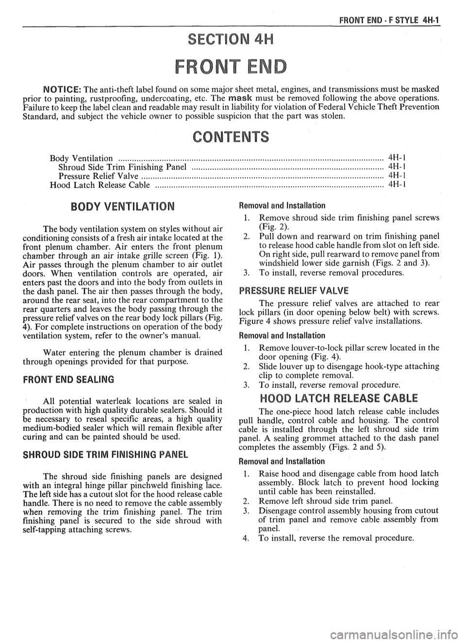
FRONT END - F STYLE 41-1-1
SECTION 4H
FRONT END
NOTICE: The anti-theft label found on some major sheet metal, engines, and transmissions must be masked
prior to painting, rustproofing, undercoating, etc. The
mask must be removed following the above operations.
Failure to keep the label clean and readable may result in liability for violation of Federal Vehicle Theft Prevention
Standard, and subject the vehicle owner to possible suspicion that the part was stolen.
CONTENTS
.............................................................................................................. Body Ventilation 4H- 1
Shroud Side Trim Finishing Panel ................................................................................ 4H- 1
Pressure Relief Valve .................................................................................................. 4H- 1
Hood Latch Release Cable ............................................................................................ 4H- 1
The body ventilation system on styles without air
conditioning consists of a fresh air intake located at the
front plenum chamber. Air enters the front plenum
chamber through an air intake grille screen (Fig.
1).
Air passes through the plenum chamber to air outlet
doors. When ventilation controls are operated, air
enters past the doors and into the body from outlets in
the dash panel. The air then passes through the body,
around the rear seat, into the rear compartment to the
rear quarters and leaves the body passing through the
pressure relief valves on the rear body lock pillars (Fig.
4). For complete instructions on operation of the body
ventilation system, refer to the owner's manual.
Water entering the plenum chamber is drained
through openings provided for that purpose.
FRONT END SEALING
All potential waterleak locations are sealed in
production with high quality durable sealers. Should it
be necessary to reseal specific areas, a high quality
medium-bodied sealer which will remain flexible after
curing and can be painted should be used.
SHROUD SIDE TRIM FINISHING PANEL
Removal and Installation
1. Remove shroud side trim finishing panel screws
(Fig. 2).
2. Pull down and rearward on trim finishing panel
to release hood cable handle from slot on left side.
On right side, pull rearward to remove panel from
windshield lower side garnish (Figs.
2 and 3).
3. To install, reverse removal procedures.
PRESSURE RELIEF VALVE
The pressure relief valves are attached to rear
lock pillars (in door opening below belt) with screws.
Figure
4 shows pressure relief valve installations.
Removal and Installation
1. Remove louver-to-lock pillar screw located in the
door opening (Fig.
4).
2. Slide louver up to disengage hook-type attaching
clip to complete removal.
3. To install, reverse removal procedure.
HOOD LATCH RELEASE CABLE
The one-piece hood latch release cable includes
pull handle, control cable and housing. The control
cable is installed through the left shroud side trim
panel. A sealing grommet attached to the dash panel
completes the assembly (Figs. 2 and
5).
Removal and Installation
The shroud side finishing panels are designed
with an integral hinge pillar pinchweld finishing lace.
The left side has a cutout slot for the hood release cable
handle. There is no need to remove the cable assembly
2.
when removing the trim finishing panel. The trim 3.
finishing panel is secured to the side shroud with
self-tapping attaching screws.
4.
Raise hood and disengage cable from hood latch
assembly. Block latch to prevent hood locking
until cable has been reinstalled.
Remove left shroud side trim panel.
Disengage control assembly housing from cutout
of trim panel and remove
cable assembly from
panel.
To install, reverse the removal procedure.
Page 1714 of 1825
DOORS - F STYLE 5H-1
SEC"610N 5H
DOORS
NOTICE: The anit-theft label found on some major sheet metal, engines, and transmissions must be masked
prior to painting, rustproofing, undercoating, etc. The mask
must be removed following the above operations.
Failure to keep the label clean and readable may result in liability for violation of Federal Vehicle Theft Prevention
Standard, and subject the vehicle owner to possible suspicion that the part was stolen.
Door Trim
...................................................... 5H- 1
Armrest and Pull Handle .......................... 5H- 1
Mirror Remote Controls/Bezel ................... 5H- 1
Inside Handles and Cover Plates ................ 5H- 1
Lock Knob .................................... .... ........... 5H-2
Trim Panel Assemblies .............................. 5H-2
Doors ............................................................ 5H-3
Door Weatherstrip ....................................... 5H-4
Side Roof Rail Weatherstrip ....................... 5H-4
Window Belt Sealing Strips ......................... 5H-6
Insulator Pads - Optional ............................ 5H-6
Inner Panel Water Deflectors ...................... 5H-6
Door Hinge System .................................. .... 5H-7
Door Side Hinge Strap ............................... 5H-8
Body Side Hinge Strap ................................ 5H- 10
Door Window ..................... .. ................... 5H- 10
Window Sash Channel ................................. 5H- 1 1
Window Regulator and Motor .................... 5H- 1 1
Filler Assembly (at Belt) ......................... ... . 5H- 13
Up Stop ............................ .. ...................... 5H- 14
Rear Guide Channel .................................... 5H- 15
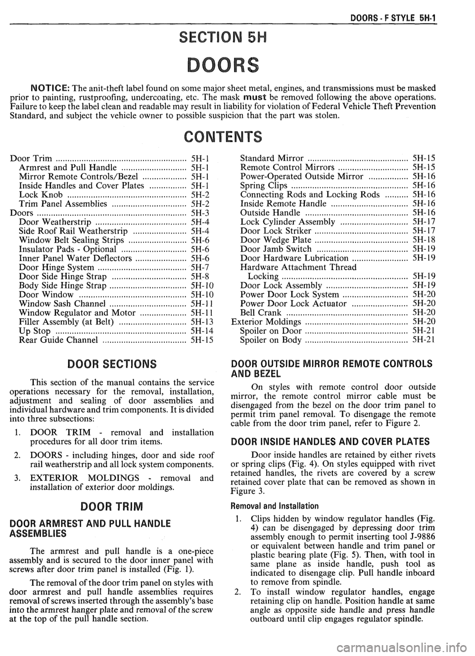
DOOR SECnONS
This section of the manual contains the service
operations necessary for the removal, installation,
adjustment and sealing of door assemblies and
individual hardware and trim components. It is divided
into three subsections:
1. DOOR TRIM
- removal and installation
procedures for all door trim items.
2. DOORS - including hinges, door and side roof
rail weatherstrip and all lock system components.
3. EXTERIOR MOLDINGS - removal and
installation of exterior door moldings. Standard Mirror
......................................... 5H- 15
........................... Remote
Control Mirrors 5H- 15
Power-Operated Outside Mirror ................. 5H-16
Spring Clips .................................................. 5H- 16
Connecting Rods and Locking Rods .......... 5H-16
Inside Remote Handle ................................ 5H- 16
......................................... Outside Handle 5H- 16
............................. Lock Cylinder Assembly 5H- 17
...................................... Door Lock Striker 5H- 17
....................................... Door Wedge Plate 5H- 18
....................................... Door Jamb Switch 5H- 19
........................ Door Hardware Lubrication 5H- 19
Hardware Attachment Thread
.................................................. Locking 5H- 19
................................... Door Lock Assembly 5H- 19
............................ Power Door Lock System 5H-20
........................ Power Door Lock Actuator 5H-20
............. .................................... Bell Crank ... 5H-20
.......................................... Exterior Moldings 5H-20
.......................................... Spoiler on Door 5H-21
.......................................... Spoiler on Body 5H-2 1
DOOR OUTSIDE MIRROR REMOTE CONTROLS
AND BEZEL
On styles with remote control door outside
mirror, the remote control mirror cable must be
disengaged from the bezel on the door trim panel to
permit trim panel removal. To disengage the remote
cable from the door trim panel, refer to Figure
2.
DOOR INSIDE HANDLES AND COVER PLATES
Door inside handles are retained by either rivets
or spring clips (Fig.
4). On styles equipped with rivet
retained handles, the rivets are covered by a screw
retained cover plate that can be removed as shown in
Figure
3.
DOOR TRIM Removal and Installation
DOOR ARMREST AND PULL HANDLE 1.
ASSEMBLIES
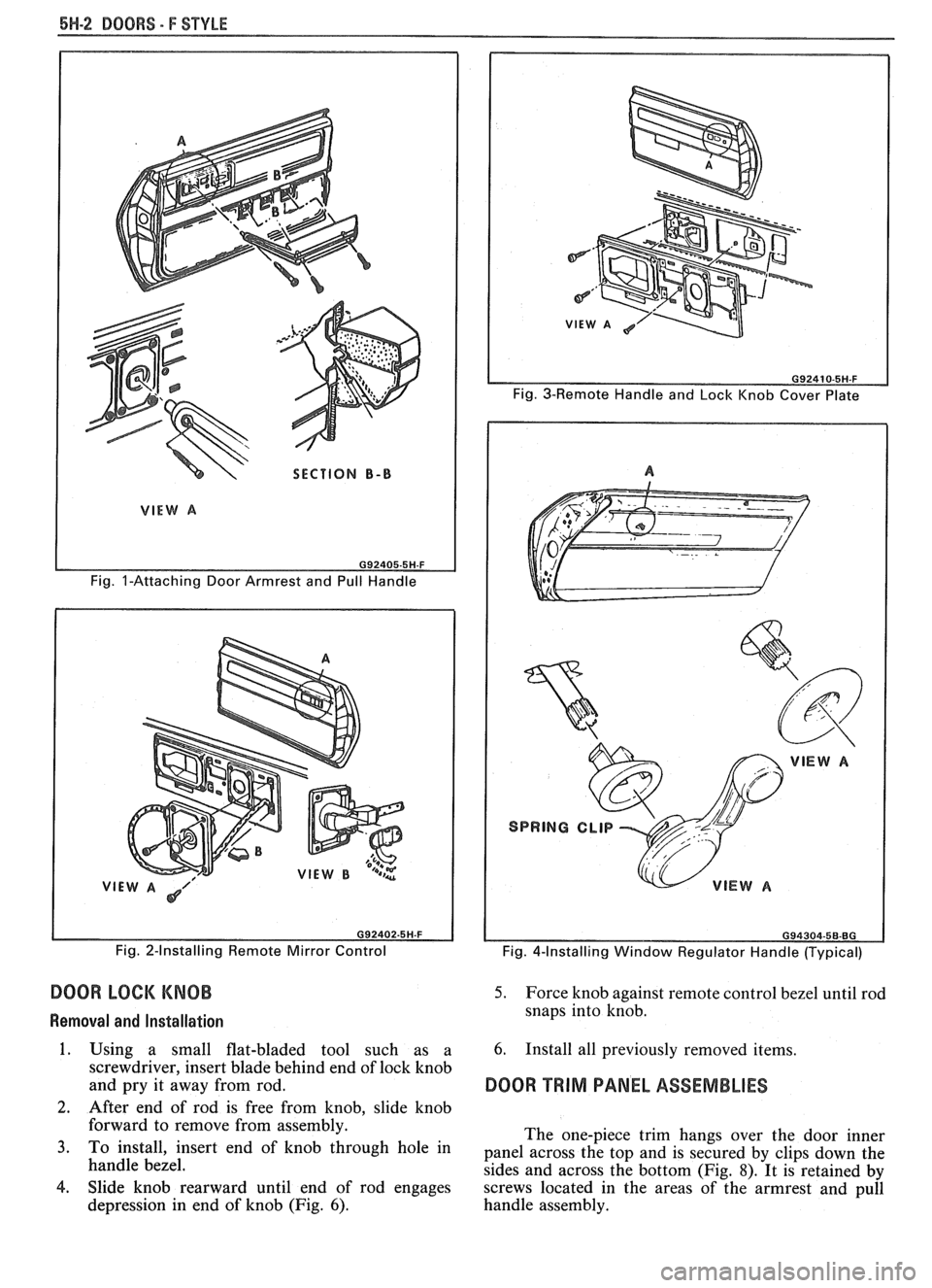
The armrest and pull handle is a one-piece
assembly and is secured to the door inner panel with
screws after door trim panel is installed (Fig. 1). Clips hidden
by window regulator handles (Fig,
4) can be disengaged by depressing door trim
assembly enough to permit inserting tool J-9886
or equivalent between handle and trim panel or
plastic bearing plate (Fig.
5). Then, with tool in
same plane as inside handle, push tool as
indicated to disengage clip. Pull handle inboard
The removal of the door trim panel on styles with to
remove from
s$n>le. -
door armrest and pull handle assemblies requires 2. To install window regulator handles, engage
removal of screws inserted through the assembly's base retaining clip on handle. Position handle at same
into the armrest hanger plate and removal of the screw angle as opposite side handle and press handle
at the top of the pull handle section.
outboard until clip engages regulator spindle.
Page 1715 of 1825
6H-2 DOORS - F STYLE
SECTION B-B
Fig. I-Attaching Door Armrest and Pull Handle
VIE Fig. 2-Installing Remote Mirror Control
DOOR LOCK KNOB
Removal and Installation
1. Using a small flat-bladed tool such as a
screwdriver, insert blade behind end of lock knob
and pry it away from rod.
2. After end of rod is free from knob. slide knob
Fig. 3-Remote Handle and Lock Knob Cover Plate
Fig. 4-Installing Window Regulator Handle (Typical)
5. Force knob against remote control bezel until rod
snaps into knob.
6. Install all previously removed items.
DOOR TRIM PANEL ASSEMBLIES
forward to remove from assembly.
The one-piece trim hangs over the door inner
3. To install, insert end of knob through hole in panel across the top and is secured by clips down the
handle bezel.
sides and across the bottom (Fig.
8). It is retained by
4. Slide knob rearward until end of rod engages
screws located in the areas of the armrest and pull
depression in end of knob (Fig.
6). handle assembly.
Page 1716 of 1825
BOORS - F STYLE 5H-3
I
J-9886
7
RETAINING SPRING
DISENGAGED 7
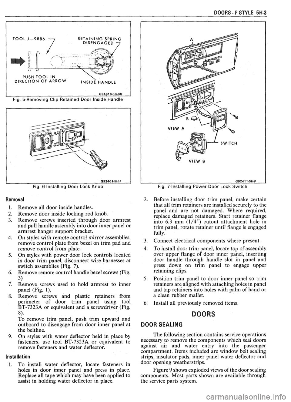
Fig. 5-Removing Clip Retained Door Inside Handle
Fig. 6-Installing Door Lock Knob
Removal
1. Remove all door inside handles.
2. Remove door inside locking rod knob.
3. Remove screws inserted through door armrest
and pull handle assembly into door inner panel or
armrest hanger support bracket.
4. On styles with remote control mirror assemblies,
remove control plate from bezel on trim pad and
remove control from plate.
5. On styles with power door lock controls located
in door trim panel, disconnect wire harnesses at
switch assemblies (Fig. 7).
6. Remove remote control handle bezel screws (Fig.
3)
7. Remove
screws used to hold armrest to inner
panel (Fig.
1).
8. Remove screws and plastic retainers from
perimeter of door trim panel using tool
BT-73238 or equivalent and a screwdriver (Fig.
8).
To remove trim panel, push trim upward and
outboard to disengage from door inner panel at
the beltline.
9. On styles with water deflector held in place by
fasteners, use tool BT-7323A or equivalent to
remove fasteners and water deflector.
Installation
1. To install water deflector, locate fasteners in
holes in door inner panel and press in place.
Replace all tape which may have been applied to
assist in holding water deflector in place.
Fig. 7-Installing Power Door Lock Switch
2. Before installing door trim panel, make certain
that all trim retainers are installed securely to the
panel and are not damaged. Where required,
replace damaged retainers. Start retainer Range
into 6.3 mm
(1/4") cutout attachment hole in
trim panel, rotate retainer until flange is engaged
fully.
3. Connect electrical components where present.
4. To install door trim panel, locate top of assembly
over upper flange of door inner panel, inserting
door handle through handle slot in panel and
press down on trim panel to engage upper
retaining clips.
5. Position trim panel to door inner panel so trim
retainers are aligned with attaching holes in panel
and tap retainers into holes with palm of hand or
a clean rubber mallet.
6. Install all previously removed items.
BOORS
DOOR SEALING
The following section contains service operations
necessary to remove the components which seal doors
against air and water entry into the passenger
compartment. Items included are window belt sealing
strips, insulator pads, inner panel water deflector and
door opening weatherstrips.
Figure
9 shows exploded views of the door sealing
components. Most parts shown are available through
the service parts system.
Page 1729 of 1825

5H-16 DOORS. F STYLE
3; To install, reverse removal procedure. Tighten
nuts to 8
N-m (72 in-lb) torque.
Remote Mirror Face Replacement
CAUTION: To minimize the chance of
personal injury,
gloves and safety
glasses should be worn when
removing broken glass.
NOTICE: When breaking mirror, cover painted
surface of door to avoid damage.
1. To remove a scratched, broken, stained, etc.,
mirror face from the frame, tape, then break the
mirror glass and remove the broken glass and
fiber pad from the mirror frame.
2. Wipe inside of mirror frame clean.
3. To
install replacement mirror face, remove paper
backing from service mirror face and center
mirror in mirror frame. Press firmly to ensure
adhesion of the mirror face to the mirror frame.
POWER-OPERATED BIIXSIDE MIRRORS
Mirror Case and Motor Removal and Installation
Follow instructions which are included with new
service part. Use electrical tape to protect electrical
connections.
Mirror Housing Removal and Installation
1. From door trim panel side, remove remote
control mirror bezel, release and remove door
panel as described in Door Trim section and
disconnect wire harness connection from remote
mirror electrical switch.
2. Peel back water deflector enough to detach
harness from retaining tabs in door.
3. Remove mirror base-to-door stud nuts and lift
mirror housing and harness assembly from door.
4. To install, reverse removal procedure.
SPRING CLIPS
Spring clips are used to secure remote control
connecting rods and inside locking rods to door lock
levers and remote handles.
A slot in the clip provides
for disengagement of the clips, allowing easier
detachment of linkage.
Removal and lnstallation
To disengage a spring clip, use a screwdriver or
other suitable thin-bladed tool to slide clip out of
engagement as shown in Figure 34. To install, reverse
removal procedure.
CONNECTING RODS AND LOCKING RODS
Rods are used to connect the door lock actuating
levers with the inside and outside handles and the
inside lock knob. The rods are attached to the lock with
spring clips.
LOCK LEVER
( $&
DISENGAGE TANG / INSERT To
Fig. 34-Removing Spring Clip
Removal and Installation
1. Remove door trim panel and detach inner panel
water deflector enough to gain access to required
parts.
2. To remove any rod, disengage spring clip
retaining rod to lock lever, then disengage rod.
Spring clip removal is shown in Figure 34. To
remove inside remote handle connecting rod,
spring clip retaining rod to remote handle must
also be disengaged. To remove inside lock knob
to lock rod, first remove knob as described in trim
portion of this section.
3. To
reinstall rods, first reengage spring clips on
lock levers. Align rod in installed position and
engage rod in proper lock lever until held by
spring clip.
INSIDE REMOTE HANDLE
Removal and lnstallation
1. Remove door trim panel and detach inner panel
water deflector enough to gain access to remote
handle (Fig. 35).
2. Disengage connecting rod clip at remote handle
and disconnect rod.
3. Punch out center pin of attaching rivet (item
2,
Fig. 35); then drill out rivet using 4.8 mm (3/16")
drill bit.
4. Slide
remote handle forward to disengage front
retaining tab and remove.
5. To install, reverse removal procedure. Use steel
rivet, 3/16"
dia, x 5/16" length (USM Part No.
SD62BS or equivalent), to attach remote handle.
OUTSIDE HANDLE
Removal and lnstallation
1. Raise door window to full-up position. Remove
door trim panel and detach inner panel water
deflector enough to expose rear access hole.
2. Remove outside handle to lock rod by
disengaging clip on outside handle (Fig. 36).
3. Remove two attaching nuts on handle studs.
4. Rotate handle up to disengage from attaching
holes.
5. To install, reverse removal procedure.
Page 1730 of 1825

DOORS - F STYLE 5W.17
1. INSIDE REMOTE HANDLE
2. ATTACHING RIVET
3. TRIM PANEL
Fig. 35 - Installing Inside Remote Handle
LOCK CYLINDER ASSEMBLY
Removal and Installation
1. Raise door window. Remove door trim panel and
detach inner panel water deflector enough to
expose access hole.
2. Disengage lock cylinder
to lock rod at cylinder
(Fig. 36).
CAUTION: If removing lock cylinder
retainer by hand, wear gloves to
prevent personal injury.
3. With a screwdriver or similar tool, slide lock
cylinder retainer forward until disengaged.
Retainer can also be removed by hand by
grasping anti-theft shield at top of retainer and
rotating until disengaged. Remove lock cylinder
from door.
4. To install, reverse removal procedure. Be sure
gasket is installed properly.
5. Black lock cylinders should be lubricated with a
light oil. All other lock cylinders should be
lubricated with a general purpose silicone
lubricant, part no. 1052277 or equivalent.
DOOR LOCK STRIKER
The door lock striker consists of a single metal
bolt and washer assembly that is threaded into a
tapped, floating cage plate located in the body lock
pillar. The door is secured in the closed position when
the door lock fork bolt snaps over and engages the
striker bolt. The striker has provisions for fore and aft
adjustment only.
1. ROD, OUTSIDE HANDLE TO LOCK
2. OUTSIDE DOOR HANDLE
3. LOCK CYLINDER
4. LOCK CYLINDER GASKET
5. LOCK CYLINDER RETAINER
6. DOOR LOCK ASSEMBLY
7. ROD, LOCK CYLINDER TO LOCK
G92412-5H.F
Fig. 36-Door Locking Mechanism
Adjust (Fig. 37)
To determine if striker fore or aft adjustment is
required, proceed as follows:
1. Make certain door is properly aligned.
2. Apply modeling clay or body caulking compound
to lock bolt opening.
3. Close
door only as far as necessary for striker bolt
to form an impression in clay or caulking
compound. Complete door closing will make clay
removal very difficult.
4. Striker impression should be centered fore and
aft. The minimum allowable measurement for
dimension
X is 2 mm (3/32"). The maximum
allowable measurement for dimension
X is 4 mm
(5/32").
A 2 mm (3/32") spacer, part no. 4469196 or
equivalent, can be used to achieve the desired
alignment.
5. If adjustment is necessary, insert tool
J23457,
BT7107 or equivalent into the star-shaped recess
in the head of the striker and loosen striker bolt.