lights PONTIAC FIERO 1988 Service Repair Manual
[x] Cancel search | Manufacturer: PONTIAC, Model Year: 1988, Model line: FIERO, Model: PONTIAC FIERO 1988Pages: 1825, PDF Size: 99.44 MB
Page 21 of 1825
OB-4 MAINTENANCE AND LUBRICATION
Tire and wheel operation - Be alert to a vibra-
tion of the steering wheel or seat at normal highway
speeds. This may mean a wheel balance is needed. Also, a
pull right or left on a straight, level road may show the
need for
a tire pressure adjustment or wheel alignment.
Steering system operation - Be alert to
changes in steering action. An inspection is needed when
the steering wheel is harder to turn or has too much free
play or if unusual sounds are noted when turning or
parking.
Headlight aim operation - Take note of light
pattern occasionally. If beam aim doesn't look right,
headlights should be adjusted.
AT EACH FUEL FILL
Engine oil level check - Check engine oil level
and add if necessary. See your Owner's
Manual for further
details.
NOTICE: A large loss in this system may indicate a
problem. Have it inspected and repaired at once.
Engine coolant level and condition - Check
engine coolant level in coolant reservoir tank and add if
necessary. Replace if dirty or rusty. See your Owner's
Manual for further details.
NOTICE: A large loss in this system may indicate a
problem. Have it inspected and repaired at once.
Windshield washer fluid level check -- Check
washer fluid level in container and add if necessary.
Hood latch operation - When opening hood on
cars equipped with hoods that open from the front, note
the operation of secondary latch. It should keep hood from
opening all the way when primary latch is released. Make
sure that hood closes firmly.
AT LEAST MONTI-ILY
Tire and wheel inspection and pressure
check--
Check tires for abnormal wear or damage. Also,
check for damaged wheels. Keep pressures as shown on
Tire Placard on the driver's door (include spare unless it is
a stowaway). Pressure should b\: checked when tires are
"cold". See "Tires" in Owner's Manual for further
infomation.
Light operation check - Check operation of
license plate light, side-marker lights, headlights includ-
ing high beams, parking lights, taillights, brake lights.
turn signals, backup lights, instrument panel and interior
lights and hazard warning flashers.
Fluid leak check - After the car has been parked
for a while, inspect the surface beneath the car for water,
oil, fuel or other fluids. Water dripping from the air
conditioning system after use is normal. If you notice fuel
leaks or fumes, the cause should be found and corrected at
once.
AT LEAST TWICE A YEAR (FOR EXAMPLE,
EVERY SPRING AND FALL)
Power steering pump fluid level check --
Check power steering pump fluid level in accordance with
Owner's Manual instructions and keep at proper level.
NOTICE: A large loss in this system may indicate a
problem. Have it inspected and repaired at once.
Brake master cylinder reservoir fluid level
check ---- Check fluid and keep at proper level. Note: It is
normal for the brake fluid level to go down slightly as the
brake pads wear
- so be sure to keep reservoir filled.
NOTICE: A large loss in this system may indicate a
problem. Have
it inspected and repaired at once.
Clutch system service --- manual transmis-
sionltransaxle --- For cars equipped with hydraulic
clutch system, check the reservoir fluid level and add fluid
as required. All others, check clutch pedal free travel and
adjust as necessary. See your Owner's Manual for further
details.
~
NOTICE: A large loss in this system may indicate a
problem. Have it inspected and repaired at once.
Weatherstrip Lubrication - Clean surface and
then apply a thin film of silicone grease with a clean cloth.
EACH TIME OIL IS CHANGED
Automatic and manual transmissionltrans-
axle fluid level check - Check transmission/transaxle
fluid level and add as required. (Corvette only) if equipped
with manual transmission
- check fluid in the overdrive
unit and add as required.
NOTICE: A large loss in this system may indicate a
problem. Have
it inspected and repaired at once.
Brake systems inspection - For convenience,
the following should be done when wheels are removed
for rotation: Inspect lines and hoses for proper hookup,
binding, leaks, cracks, chafing, etc. Inspect disc brake
pads for wear and rotors for surface condition. Also in-
spect drum brake linings for wear and cracks. Inspect
other brake parts, including drums, wheel cylinders, park-
ing brake, etc. at the same time. Check parking brake
adjustment.
INSPECT BRAKES MORE OFTEN IF DRIVING
HABITS OR CONDITIONS RESULT IN FREQUENT
BRAKING.
Steering, suspension and front drive axle
boot and seal inspection
- Inspect front and rear
suspension and steering system for damaged, loose or
missing parts, signs of wear or lack of lubrication. Inspect
power steering lines and hoses for proper hookup, bind-
ing, leaks, cracks, chafing, etc. (On cars equipped with
manual steering gear, check for seal leakage.) On
front-
wheel-drive cars, clean then inspect drive axle boot seals
for damage, tears or leakage. Replace seals if necessary.
Exhaust system inspection - Inspect complete
system. Inspect body near the exhaust system. Look for
broken, damaged, missing or out-of-position parts as well
as open seams, holes, loose connections or other condi-
tions which could cause a heat buildup in the tloor pan or
could let exhaust fumes seep into the trunk or passenger
compartment.
Page 114 of 1825
CHASSIS SHEET METAL 2@-7
3. During the above flash time period (1 to 10 min-
utes), apply appropriate "conventional" interior acrylic lacquer color as required and allow
painted part to dry for
4 to 5 hours before install-
ing on car.
RlGlD OW HARD ABS PMS"TIC PARTS
Rigid or hard ABS plastic requires no primer.
"Conventional" interior acrylic lacquers adhere satis-
factorily to hard ABS plastics.
Procedure
1. Wash part thoroughly with a cleaning solvent
(Acrylic-Clean, Pre-Kleano, Prep-Sol or equiv-
alent) to remove any dirt or grease.
2. Apply appropriate "conventional" interior
acrylic lacquer color. Apply only sufficient
color for proper hiding to avoid washout of
"grain" effect.
3. Allow to dry and then install part.
VINYL AND FLEXIBLE (Son) ABS
PLASTIC PARTS
The outer cover or skin material of "flexible"
instrument panel cover (pad) assemblies is made of an
ABSIPVC plastic blend. The same is true of many
"padded" door trim assemblies. The soft cushion pad-
ding under the I.P. skin is urethane foam plastic. The
most widely used
"flexible" vinyls (poly vinyl chlo-
ride)
are coated fabrics, such as used in seat trim,
some door trim assemblies, molded headlining panels
and sun visors. Most head rests are "flexible" vinyls.
Examples of "hard vinyls are: door and front seat
back assist handles and coat hooks.
The paint system of vinyl and flexible ABS
plastic involves the use of interior "vinyl" color and a
clear vinyl top coat.
Procedure
1. Wash part thoroughly with a vinyl cleaning and
preparation solvent ("Vinyl Press"
- Ditzler,
"Vinyl Prep Conditioner"
- Detroit Autobody
or equivalent) to remove greasy film or silicone.
Wipe off cleaner while still wet with clean,
lint-
free cloth.
2. Immediately after wiping face dry, apply inte-
rior "vinyl" color in wet coats allowing suffi-
cient flash time between coats (see label
directions on can). Use proper "vinyl" color as
designated by interior trim combinations. Apply
only sufficient color for proper hiding to avoid
washout of "grain" effect. No primer or
primer-
sealer is required.
3. Before the final vinyl color coat has dried, apply
two coats of clear vinyl top coat spray (instru-
ment panels will require the "nonglare" clear top
coat). Do not allow the first spray coat to com-
pletely dry before spraying on the second. Use
top coat with appropriate gloss level to match adjacent similar components. This
clear coat is
necessary to control the gloss requirement and
prevent
'tracking" (rubbing-off) of the color
coat after drying.
4. Allow to dry according to label directions before
installing part.
ON-VEHICLE SERVICE
CONCEALED HEADLIGHTS
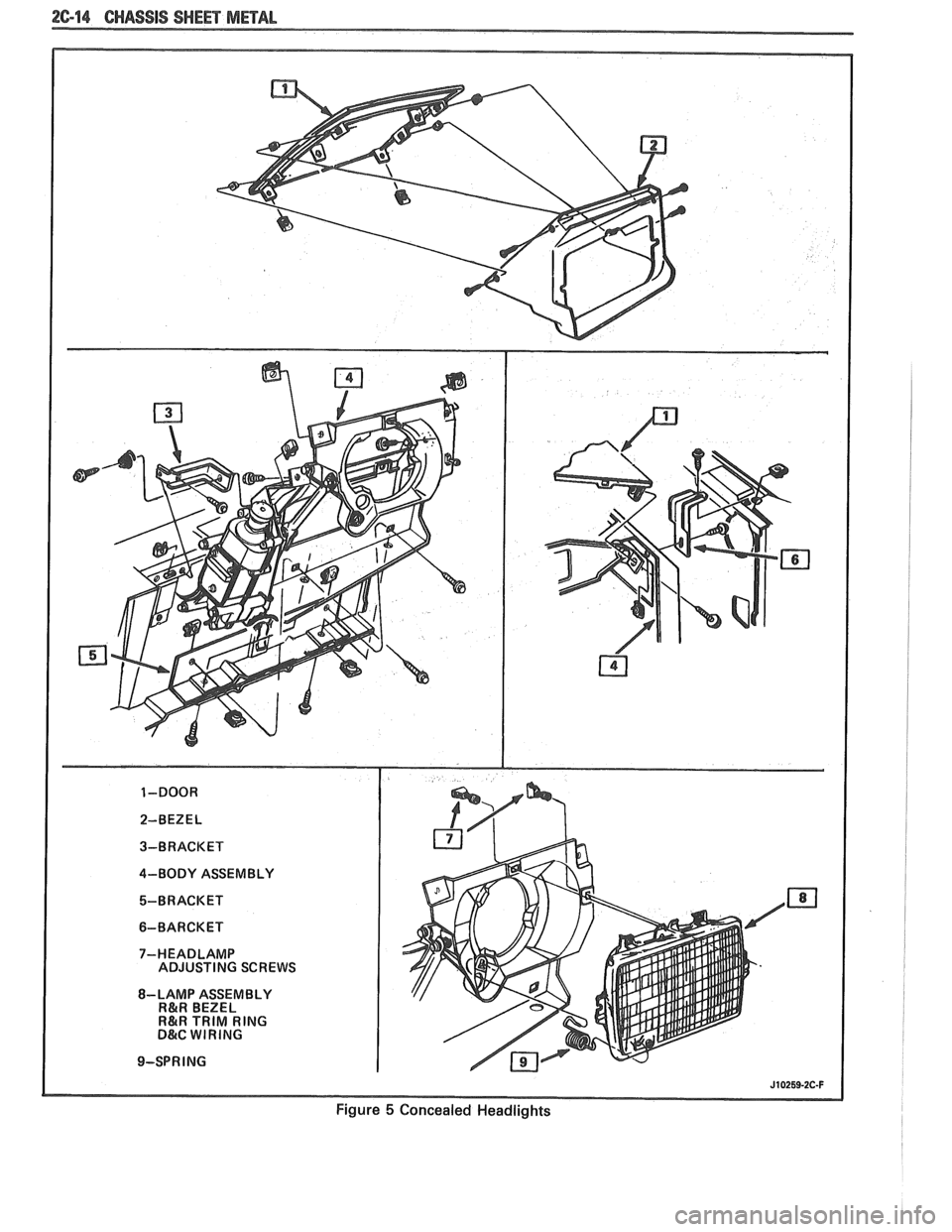
The concealed headlights used on this model are
electrically operated. When the headlights are turned
on, solid state circuitry activates the actuators. This
same circuitry senses when the actuators stop moving
and removes the ground to deactivate the actuators.
When the headlights are turned off, the actuators run
in opposite direction closing the headlight doors.
Should an electrical failure occur in the head-
light circuit, they may be raised manually by rotating
the knob on the actuator in a counterclockwise direc-
tion until the headlights are fully open. The headlights
may be lowered by rotating the knob on the actuator in
a clockwise direction until the headlights are fully
closed.
For electrical circuit information and diagnosis,
refer to Section
8A of this manual.
If it is desired to raise the headlights with the
lights off, either of the following procedures may be
used:
1. Turn the lights on. After the headlights are
open, disconnect the electrical connections at
the actuator connectors. Turn the lights off. The
headlights will now remain in the open position.
2. Turn the parking lights on. Depress the head-
light rocker switch lightly. The headlights may
then be raised "up" fully with the lights off.
Adjust
Because of the number of adjustments possible
and the number of attaching points of the concealed
headlight body assembly
(9), only those attachments
which control the adjustment desired should be loos-
ened. Make one
adjbstment at a time.
NOTICE: The headlight door does NOT have
slotted mounting holes and therefore is not
adjustable by itself. This insures proper clearance
between the headlight door and the hood and
fenders in both the raised and lowered positions.
The entire headlight body assembly must be
adjusted to achieve the desired appearance and
fit. Care should be exercised when adjusting the
headlight body assembly. Severe hammer blows could damage the die cast aluminum headlight
body assembly.
TO RAISE OR LOWER the headlight body
assembly, proceed as follows:
1. Open hood.
2. Raise headlights.
Page 115 of 1825
26-8 CHASSIS SWEET METAL
3. Remove headlight bezel.
4. If necessary, move battery rearward to gain
access to rear screw.
5. Lower headlights.
6. Loosen two body screws and adjust headlight
body.
7. If a satisfactory appearance is still not obtained,
remove lower air deflector to gain access to
number 1 and number 2 screws.
8. Loosen two body screws and adjust headlight
body.
9. Repeat procedure, if necessary, to obtain a satis-
factory appearance.
10. Re-position battery and tighten hold-down
screw to specifications.
11. Install lower air deflector.
12. Install headlight bezel.
TO SET FRONT TO REAR
GAP between
headlight door and hood, proceed as follows:
1. Open hood.
2. Raise headlights.
3. Remove headlight bezel.
4. Lower headlights.
5. Loosen two body assembly screws and adjust
headlight body assembly.
6. If a satisfactory appearance is still not obtained,
remove lower air deflector to gain access to two
lower screws.
7. Loosen two lower screws and adjust headlight
body assembly.
8. Repeat procedure, if necessary.
9. Install lower air deflector.
10. Install headlight bezel.
TO SET SIDE-TO-SIDE GAP between head-
light door and hood and headlight door and fender,
proceed as follows:
Open hood.
Raise headlights. Remove headlight bezel.
If necessary, move battery rearward to gain
access to rear screw.
Lower headlights.
Loosen three body screws and adjust headlight
body.
If a satisfactory appearance is still not obtained,
remove lower air deflector to gain access to two
lower screws.
Loosen two lower screws and adjust headlight
body.
Repeat procedure, if necessary.
Re-position battery and tighten hold-down
screw to specifications.
Install lower air deflector.
Install headlight bezel. TO
SET CONTOUR of headlight door to hood,
proceed as follows:
1. Open hood.
2. Raise headlights.
3. Remove headlight bezel.
4. Lower headlights.
5. Loosen two (2) screws and adjust headlight
body assembly.
6. If a satisfactory appearance is still not obtained,
remove lower air deflector to gain access to two
lower screws.
7. Loosen two lower screws and adjust headlight
body assembly.
8. Repeat procedure, if necessary.
9. Install lower air deflector.
10. Install headlight bezel.
HEADLIGHT BODY ASSEMBLY
Remove or Disconnect
1. Rear headlight door attaching screws.
2. Raise headlight doors.
3. Headlight bezel attaching screws.
4. Front headlight door attaching screws and
remove headlight door.
5. Electrical connection at bulb.
6. Lower air deflector (one side only).
7. Headlight body assembly attaching screws and
disconnect electrical connection at actuator
connector.
8. Link.
9. Actuator crank arm.
10. Actuator retaining screws and remove actuator.
11. Unhook headlight capsule lower retaining
spring and remove headlight capsule assembly.
12. Headlight body assembly attaching brackets and
fasteners.
Install or Connect
1. Headlight body assembly attaching brackets and
fasteners.
2. Headlight capsule lower retaining spring and
install headlight capsule
3. Acuator retaining screws and install actuator.
4. Actuator crank arm.
5. Link.
6. Headlight body assembly attaching screws and
connect electrical connection at actuator
connector.
7. Lower air deflector (one side only).
8. Electrical connection at bulb.
9. Front headlight door attaching screws and install
headlight door.
Page 121 of 1825
2C-14 CHASSIS SHEET METAL
J10259-2C-F
Figure 5 Concealed Headlights
Page 131 of 1825
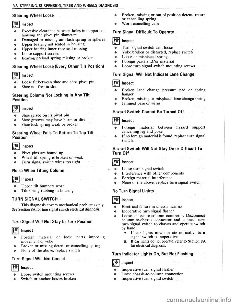
3-6 STEERING, SUSPENSION, TIRES AND WHEELS DIAGNOSIS
Steering Wheel Loose
lnspect
Excessive clearance between holes in support or
housing and pivot pin diameters
e Damaged or missing anti-lash spring in spheres
e Upper bearing not seated in housing
e Upper bearing inner race seal missing
e Loose support screws
e Bearing preload spring missing or broken
Steering Wheel Loose (Every Other Tilt Position)
lnspect
e Loose fit between shoe and shoe pivot pin
e Shoe not free in slot
Steering Column Not Locking In Any Tilt
Position
lnspect
e Shoe seized on its pivot pin
e Shoe grooves may have burrs or dirt
e Shoe lock spring weak or broken
Steering Wheel Fails To Return To Top Tilt
Position
Inspect
e Pivot pins are bound up
e Wheel tilt spring is broken or weak
e Turn signal switch wires too tight
Noise When Tilting Column
Inspect
e Upper tilt bumpers worn
e Tilt spring rubbing in housing
TURN SIGNAL SWITCH
This diagnosis covers mechanical problems only
See Section
8A for turn signal switch electrical diagnosis.
Turn Signal Will Not Stay In Turn Position
lnspect
e Foreign material or loose parts impeding
movement of yoke
e Broken or missing detent or cancelling spring
s None of the above, replace switch
Turn Signal Will Not Cancel
lnspect
a Loose switch mounting screws
e Switch or anchor bosses broken
e Broken, missing or out of position detent, return
or cancelling spring
Worn cancelling cam
Turn Signal Difficult To Operate
0 Inspect
e Turn signal switch arm loose
e Yoke broken or distorted, replace switch
e Loose or misplaced springs
e Foreign parts andlor material
o Loose turn signal switch mounting screws
Turn Signal Will Not Indicate Lane Change
a Inspect
e Broken lane change pressure pad or spring
hanger
e Broken, missing or misplaced lane change spring
e Jammed base or wires
Hazard Switch Cannol: Be Turned Off
a Inspect
e Foreign material between hazard support
cancelling leg and yoke
e If no foreign material is found, replace turn signal
switch.
Hazard Switch Will Not Stay On or Difficult To
Turn Off
e Loose turn signal switch
a Interference with other components
e Foreign material interference
e None of the above, replace turn signal switch
No Turn Signal Lights
lnspect
e Electrical failure in chassis harness
e Inoperative turn signal flasher
e Loose chassis-to-column connector. Disconnect
column-to-chassis connector and connect new
turn signal switch to chassis and operate switch
by hand.
A. If car lights now operate normally, turn
signal switch is inoperative.
B. If
car lights do not operate, refer to Section 8A
for electrical diagnosis.
Turn Indicator Lights On, But Not Flashing
a Inspect
e Inoperative turn signal flasher
Loose chassis-to-column connection
Inoperative turn signal switch
Page 132 of 1825
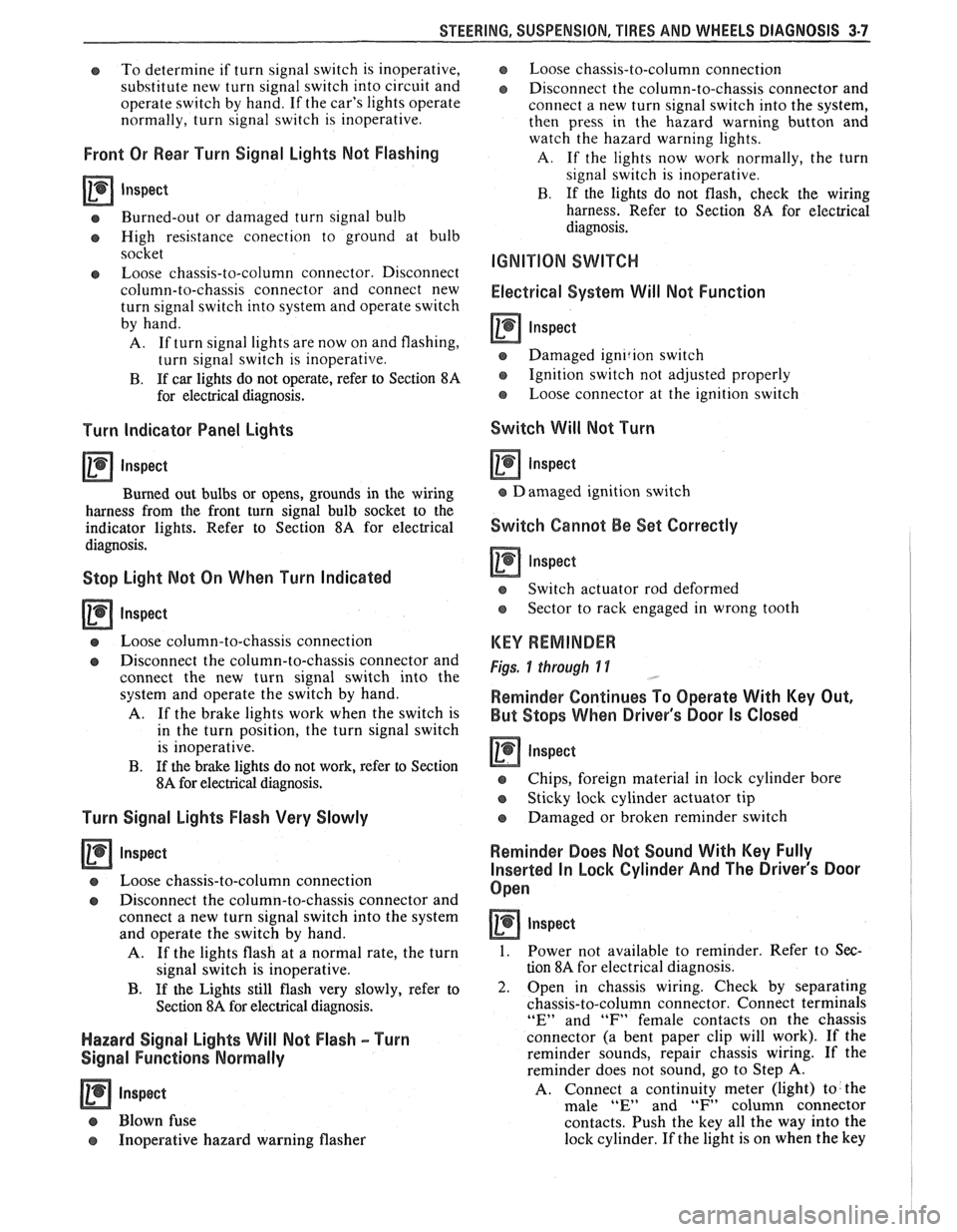
STEERING, SUSPENSION, TIRES AND WHEELS DIAGNOSIS 3-7
e To determine if turn signal switch is inoperative,
substitute new turn signal switch into circuit and
operate switch by hand.
If the car's lights operate
normally, turn signal switch is inoperative.
Front Or Rear Turn Signal Lights Not Flashing
Inspect
s Burned-out or damaged turn signal bulb
e High resistance conection to ground at bulb
socket
s Loose chassis-to-column connector. Disconnect
column-to-chassis connector and connect new
turn signal switch into system and operate switch
by hand.
A. If turn signal lights are now on and flashing,
turn signal switch is inoperative.
B. If car lights do not operate, refer to Section
8A
for electrical diagnosis.
Turn Indicator Panel Lights
Inspect
Burned out bulbs or opens, grounds in the wiring
harness from the front turn signal bulb socket to the
indicator lights. Refer to Section
8A for electrical
diagnosis.
Stop Light Mot On When Turn Indicated
Inspect
s Loose column-to-chassis connection
e Disconnect the column-to-chassis connector and
connect the new turn signal switch into the
system and operate the switch by hand.
A. If the brake lights work when the switch is
in the turn position, the turn signal switch
is inoperative.
B. If the brake lights do not work, refer to Section
8A for electrical diagnosis.
Turn Signal Lights Flash Very Slowly
e Loose chassis-to-column connection
a Disconnect the column-to-chassis connector and
connect a new turn signal switch into the system
and operate the switch by hand.
A. If the lights flash at a normal rate, the turn
signal switch is inoperative.
B. If the Lights still flash very slowly, refer to
Section
8A for electrical diagnosis.
Hazard Signal Lights Will Not Flash - Turn
Signal Functions Normally
~"SPBC~
a Blown fuse
Inoperative hazard warning flasher
e Loose chassis-to-column connection
s Disconnect the column-to-chassis connector and
connect a new turn signal switch into the system,
then press in the hazard warning button and
watch the hazard warning lights.
A. If the lights now work normally, the turn
signal switch is inoperative.
B. If the lights do not flash, check the wiring
harness. Refer to Section
8A for electrical
diagnosis.
IGNITION SWITCH
Electrical System Will Not Function
Damaged ign~rion switch
e Ignition switch not adjusted properly
e Loose connector at the ignition switch
Switch Will Not Turn
Inspect
Damaged ignition switch
Switch Cannot Be Set Correctly
Inspect
Switch actuator rod deformed
e Sector to rack engaged in wrong tooth
KEY REMINDER
Figs. 1 through 11 ,
Weminder Continues To Operate With Key Out,
But Stops When Driver's Door Is Closed
e Chips, foreign material in lock cylinder bore
Sticky lock cylinder actuator tip
Damaged or broken reminder switch
Reminder Does Not Sound With Key Fully
Inserted In Lock Cylinder And The Driver's Door
Open
Inspect
1. Power not available to reminder. Refer to Sec-
tion
8A for electrical diagnosis.
2. Open in chassis wiring. Check by separating
chassis-to-column connector. Connect terminals
"E" and "F" female contacts on the chassis
connector (a bent paper clip will work). If the
reminder sounds, repair chassis wiring. If the
reminder does not sound, go to Step
A.
A. Connect a continuity meter (light) to the
male
"E" and "F" column connector
contacts. Push the key all the way into the
lock cylinder. If the light is on when the key
Page 310 of 1825
BRAKES 5-17
maintaining proper wheel balance, brake drums should be
checked for balance. Brake drums may be checked for
balance on most off-the-car balancers.
COMBINATION VALVE
Testing Combination Valve Electrical Circuit
When removing the electrical wire connector from the
pressure differential switch, squeeze the
eliptical shaped
plastic locking ring and pull up. This will move the locking
tangs away from the switch. Pliers can be used to help
remove the connector.
1. Disconnect wire from switch terminal and use a
jumper to connect wire to a good ground.
2. Turn ignition key to "ON." The warning lamp should
light. If lamp does not light, bulb is burned out or
electrical circuit is faulty. Replace bulb or repair elec-
trical circuit as necessary.
3. When warning lamp lights, turn off ignition switch.
Disconnect jumper and connect wire to switch termi-
nal.
Testing Combination Valve Warning Lamp Switch
1. Attach a bleeder hose to a rear brake bleed screw and
immerse the other end of the hose in a container
partially filled with clean brake fluid. Be sure master
cylinder reservoirs are full.
2. Turn ignition switch to "ON." Open bleeder screw
while an assistant applies moderate pressure to the
brake pedal. Warning lamp should light. Close
bleeder screw before assistant releases brake pedal.
Apply brake pedal with moderate-to-heavy pressure.
Lamp should go out.
3. Attach the bleeder hose to a front brake bleeder
screw and repeat steps
1 and 2. Warning lamp action
should be the same as in step
2. Turn off ignition
switch.
4. If warning lamp does not light during steps 2 and 3,
but does light when a jumper is connected to ground,
the warning lamp switch portion of the combination
valve is faulty. Do not disassemble the combination
valve.
If any portion of the combination valve is faulty,
it must be replaced with a new combination valve.
Combination Valve Replacement
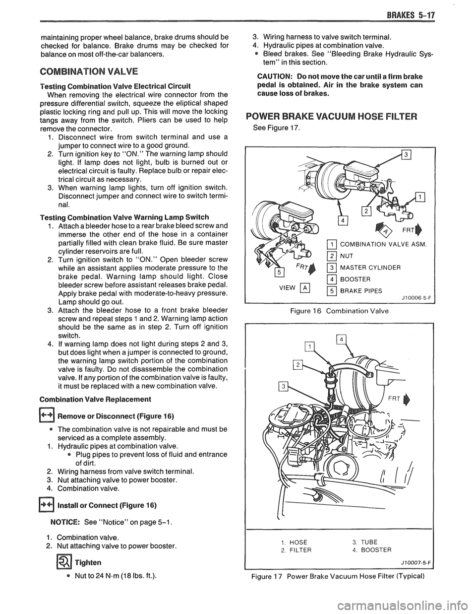
Remove or Disconnect (Figure
16)
r The combination valve is not repairable and must be
serviced as a complete assembly.
1. Hydraulic pipes at combination valve.
Plug pipes to prevent loss of fluid and entrance
of dirt.
2. Wiring harness from valve switch terminal.
3. Nut attaching valve to power booster.
4. Combination valve.
@ Install or Connect (Figure 16)
NOTICE: See "Notice" on page 5-1.
1. Combination valve.
2. Nut attaching valve to power booster.
Tighten
* Nut to 24 N.m (18 Ibs. ft.).
3. Wiring harness to valve switch terminal.
4. Hydraulic pipes at combination valve. * Bleed brakes. See "Bleeding Brake Hydraulic Sys-
tem" in this section.
CAUTION: Do not move the car until a firm brake
pedal is obtained. Air in the brake system can
cause loss of brakes.
POWER BRAKE VACUUM HOSE FILTER
See Figure 17.
COMBINATION VALVE ASM.
MASTER CYLINDER BRAKE PIPES
Figure 16 Combination Valve
2 FILTER 4. BOOSTER
Figure 17 Power Brake Vacuum Hose Filter (Typical)
Page 447 of 1825
6D1-4 BATTERY
VOLTAGE
A. 16.0 or more
B. 14.0
- 15.9
C. 13.9 or less HOURS
1. Set parking brake and place automatic
Up to 4 Hours transmission in "PARK" (NEUTRAL for
Up to 8 Hours manual transmission.) Turn off the ignition,
Up to 16 Hours turn off lights, and all other electrical
If the charge current is still not
measurable
at the end of the above charging
times, the battery should be replaced.
If the charge current is measurable during
the charging time, the battery is considered to be
good and charging should be completed in the
normal manner.
5. It
is important to remember that a completely
discharged battery must be recharged for a
sufficient number of ampere hours (AH) to
restore it to a usable state. As a general rule of
thumb, using the reserve capacity rating (RC) of
the battery as the number of ampere hours of
charge will usually bring the green dot into view.
For example, if battery is rated at 75 RC minutes,
it would be completely recharged as follows:
10 ampere charge x 7-1/2 hours
= 75 AH
25 ampere charge x 3 hours = 75 AH, etc.
6. It
is recommended that any battery recharged by
this procedure be
LOAD TESTED to establish
serviceability.
JUMP STARTING IN CASE OF EMERGENCY
WITH AUXILIARY (BOOSTER) BAVEEWY
NOTICE: Do not push or tow the vehicle to start.
Damage to the emission system, or to other parts
of the vehicle may result.
Both booster and discharged battery should be
treated carefully when using jumper cables. Follow the
procedure outlined below, being careful not to cause
sparks:
CAUTION: Departure from these
conditions or the procedure below
could result in:
(1) Serious personal
injury (particularly to eyes) or property
damage from such causes as battery
explosion, battery acid, or electrical
burns; and/or
(2) damage to electronic
components of either vehicle.
Never expose battery to open flame or electric
spark
- batteries generate a gas which is flammable and
explosive.
Remove rings, watches, and other jewelry. Wear
approved eye protection.
Do not allow battery fluid to contact eyes, skin,
fabrics, or painted surfaces
- fluid is a corrosive acid.
Flush any contacted area with water immediately and
thoroughly. Be careful that metal tools or jumper
cables do not contact the positive battery terminal (or
metal in contact with it) and any other metal on the
car, because a short circuit could occur. Batteries
should always be kept out of the reach of children.
loads.
2. Check the built-in hydrometer. If it is clear or
light yellow, replace the battery.
3. Attach the end of one jumper cable to the positive
terminal of the booster battery and the other end
of the same cable to the positive terminal of the
discharged battery. Do not permit vehicles to
touch each other as this could cause a ground
connection and counteract the benefits of this
procedure. (Use 12-volt battery only to jump start
the engine).
4. Attach one end of the remaining negative cable
to the negative terminal of the booster battery,
and the other end to a solid engine ground (such
as
A/C compresser bracket or generator
mounting bracket) at least 18 inches from the
battery of the vehicle being started (DO NOT
CONNECT DIRECTLY TO THE NEGATIVE
TERMINAL OF THE DEAD BATTERY).
5. Start the engine of the vehicle that is providing
the jump start and turn off electrical accessories.
Then start the engine in the car with the
discharged battery.
6. Reverse these directions exactly when removing
the jumper cables. The negative cable must be
disconnected from the engine that was jump
started first.
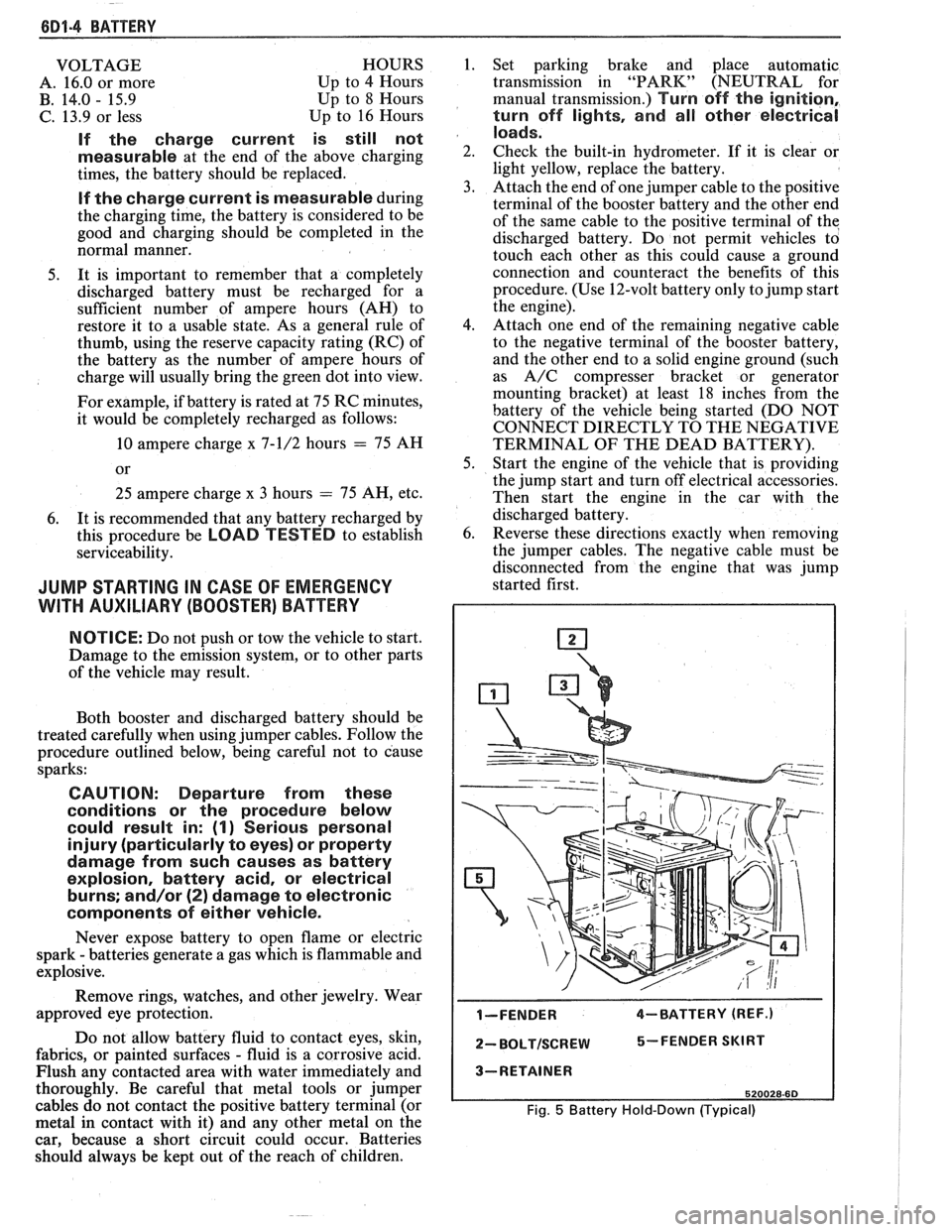
I-FENDER 4-BATTERY (REF.)
2- BOLTISCREW 5-FENDER SKIRT
3-RETAINER
520028-60
Fig. 5 Battery Hold-Down (Typical)
Page 460 of 1825
CRANKING SYSTEM BD2-9
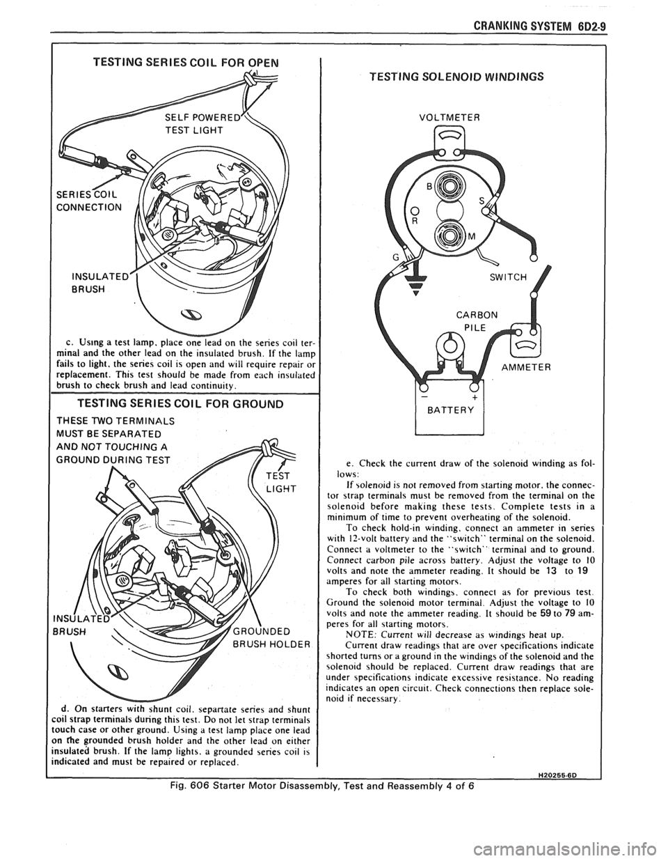
I TESTING SERIES COIL FOR OPEN I
TESTING SOLENOID WINDINGS
c. Us~ng a test lamp. place onelead on the series coil ter-
minal and the other lead on the insulated brush. If the lamp
fails to light. the series coil is open and will require repair or
replacement. This test should be made from each insulated
brush to check brush and lead continuity.
TESTING SERIES COlL FOR GROUND
THESE TWO TERMINALS
MUST BE SEPARATED
d. On starters
withshunt coil. sepanate series and shunt
coil strap terminals during this test. Do not let strap terminals
touch case or other ground. Using a test lamp place one lead
on
he grounded brush holder and the other lead on either
insulated brush. If the lamp lights, a grounded series coil is
indicated and must be repaired or replaced. VOLTMETER
e. Check the current draw of the solenoid winding as fol-
lows:
If solenoid is not removed from starting motor. the connec-
tor
strap terminals must be removed from the terminal on the
solenoid before making these tests. Complete tests in a
minimum of time to prevent overheating of the solenoid.
To check hold-in winding, connect an ammeter in series
with 12-volt battery and the "switch" terminal on the solenoid.
Connect a voltmeter to the "switch" terminal and to ground.
Connect carbon pile across battery. Adjust the voltage to
10 volts and note the ammeter reading. It should be 13 to 19 amperes for all starting motors.
To check both windings. connect as for previous test.
Ground the solenoid motor terminal. Adjust the voltage to 10
volts and note the ammeter reading. It should be
59 to 79 am-
peres for all starting motors.
NOTE: Current will decrease as windings heat up.
Current draw readings that are over specifications indicate
shorted turns or a ground in the windings of the solenoid and the
solenoid should be replaced. Current draw readings that are
under specifications indicate excessive resistance. No reading
indicates an open circuit. Check connections then replace sole-
noid if necessary.
H20255.6D
Fig. 606 Starter Motor Disassembly, Test and Reassembly 4 of 6
Page 464 of 1825
CHARGING SYSTEM 6D3-1
SECTION 6D3
CHARG NG SYSTEM
CONTENTS
General Description ................................. 6D3- 1 Charging System ........................................ 6D3- 1
.......................................... Charging System - CS ............................... 6D3- 1 On-Car Service 6D3-2
................................................... Diagnosis .. 6D3- 1 Generator 6D3-3 ...................... ......................... ............................................. 6D3- 1 Specifications 6D3-3 Service Procedures .................................. Unit Repair .. 6D3-4-6 ............................... ............
GENERAL DESCRIPTION
The engine electrical system includes the battery,
ignition (primary and secondary), starter (and related
wiring) and the generator (and related wiring).
Diagnostic charts (see Section 6D) will aid in
trouble-shooting system faults. When a fault is traced
to a particular component, refer to that components'
section of the service manual.
CHARGING SYSTEM-CS
The CS Charging System has several sizes
available, including the CS-130 and CS-144. The
number (130 or 144) denotes the
OD in mm of the
stator laminations.
CS generators use a new type regulator and a
diode trio is not used. A delta stator, rectifier bridge,
and rotor with slip rings and brushes are electrically
similar to earlier generators. A conventional pulley and
fan is used and, on the CS-130, an internal fan cools the
slip ring end frame, rectifier bridge and regulator.
Unlike three-wire generators, the CS-130 and
CS-144 may be used with only two connections
-
battery positive and an "L" terminal to the charge
indicator bulb. Use of "P",
"F", and "S" terminals is
optional. The "P" terminal is connected to the stator,
and may be connected externally to
a tachometer or other
device. The
"F" terminal is connected internally
to field positive, and may be used as a fault indicator.
The "S" terminal may be connected externally to a
voltage, such as battery voltage, to sense voltage to be
controlled.
As on other charging systems, the charge
indicator lights when the switch is closed, and goes out
when the engine is running. If the charge indicator is
on with the engine running, a charging system defect
is indicated. For all kinds of defects, the indicator will
glow at full brilliance, not "half lit". Also, the charge
indicator will be on with the engine running if system
voltage is too high or too low. The regulator voltage
setting varies with temperature, and limits system
voltage by controlling rotor field current.
This regulator switches rotor field current on and
off at a fixed frequency of about 400 cycles per second.
By varying the on-off time, correct average field
current for proper system voltage control is obtained.
At high speeds, the on-time may be 10% and the
off-time 90%. At low speeds, with high electrical loads,
on-off time may be 90% and
lo%, respectively.
No periodic maintenance on the generator is
required.
DIAGNOSIS
SERVICE PROCEDURES
CHARGING SYSTEM
The generator does not require periodic
lubrication. The rotor shaft is mounted on ball bearings
at the drive end and roller bearings at the slip ring end.
Each contains a permanent grease supply. At periodic
intervals, check mounting bolts for tightness and adjust
belt tension (see Section
6B), if applicable.
e When adjusting belt tension, apply pressure at
center of generator, never against either end
frame.
GENERATOR BENCH CHECK-CS
To check generator in a test stand, remove as
specified in On-Car Service and proceed as follows: 1.
Make connections as shown in Figure
lH, except
leave the carbon pile disconnected. The ground
polarity of generator and battery must be the
same. The battery must be fully charged. Use a
30-500
OHM resistor between battery and "L"
terminal.
2. Slowly increase generator speed and observe
voltage.
3. If the voltage is uncontrolled and increases above
16.0 volts, the rotor field is shorted, the regulator
is defective, or both.
A shorted rotor field coil can
cause the regulator to become defective. NOTE:
The battery must be fully charged when making
this test.