key battery PONTIAC FIERO 1988 Service User Guide
[x] Cancel search | Manufacturer: PONTIAC, Model Year: 1988, Model line: FIERO, Model: PONTIAC FIERO 1988Pages: 1825, PDF Size: 99.44 MB
Page 545 of 1825
6E2-A-54 5.OL (VIN E) DRIVEABILITY AND EMISSIONS
465 DK GRNMlHT
450 BLWHT
FUEL PUMP BATTERY JUNCTION TEST TERM. BULKHEAD BODY CONNECTOR
BLOCK (12 VOLT) CONNECTOR
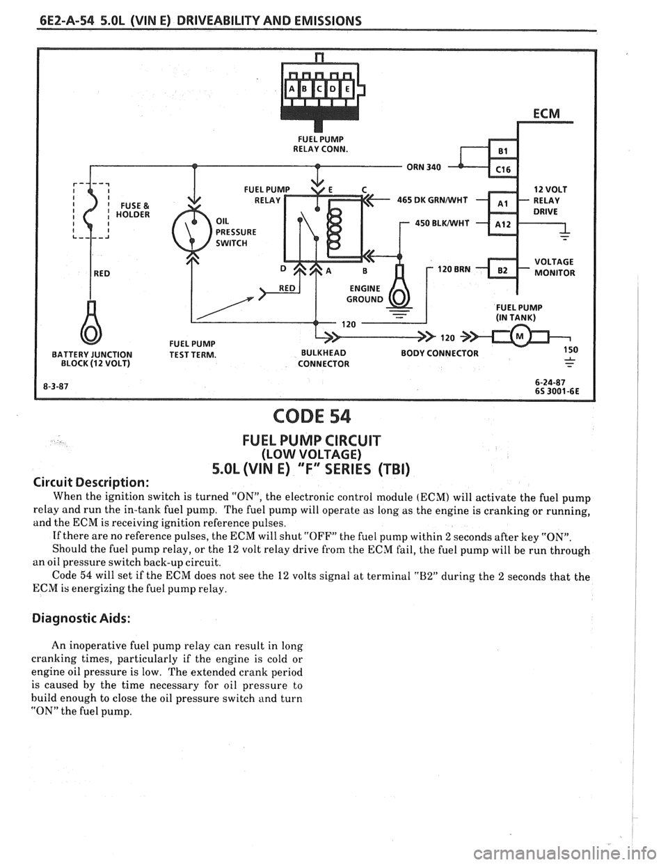
CODE 54
FUEL PUMP CIRCUIT
(LOW VOLTAGE)
5.OL (VIN E) "F"" SERIES (TBI)
Circuit Description:
When the ignition switch is turned "ON", the electronic control module (ECM) will activate the fuel pump
relay and run the in-tank fuel pump. The fuel pump will operate as long as the engine is cranking or running,
and the ECM is receiving ignition reference pulses.
If there are no reference pulses, the ECM will shut
"OFF" the fuel pump within 2 seconds after key "ON".
Should the fuel pump relay, or the
12 volt relay drive from the ECM fail, the fuel pump will be run through
an oil pressure switch back-up circuit.
Code
54 will set if the ECM does not see the 12 volts signal at terminal "B2" during the 2 seconds that the
ECM is energizing the fuel pump relay.
Diagnostic Aids:
An inoperative fuel pump relay can result in long
cranking times, particularly if the engine is cold or
engine oil pressure is low. The extended crank period
is caused by the time necessary for oil pressure to
build enough to close the oil pressure switch and turn
"ON" the fuel pump.
Page 562 of 1825
DRIVEABILITY AND EMISSIONS 5.OL (VIN E) 6EZ-C1-7
BRACKET
INSTRUMENT PANEL
(INSTRUMENT PANEL) '
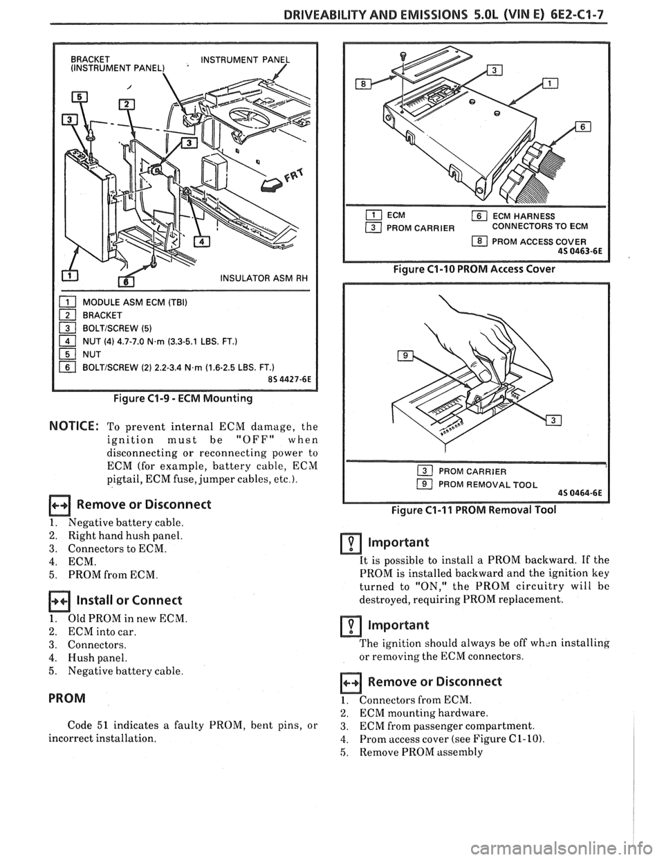
MODULE ASM ECM (TBI)
BRACKET
1 BOLTISCREW (5) - 1 NUT (4) 4.7-7.0 N.rn (3.3-5.1 LBS. FT.)
NUT
BOLTISCREW (2) 2.2-3.4 N,rn (1.6-2.5 LBS. FT.)
Figure C1-9 - ECM Mounting
NOTICE: To prevent internal ECM damage, the
ignition must be
"OFF" when
disconnecting or reconnecting power to
ECM (for example, battery cable, ECM
pigtail, ECM fuse, jumper cables,
etc.).
Remove or Disconnect
1. Negative battery cable.
2. Right hand hush panel.
3. Connectors to ECM.
4. ECM.
5. PROM from ECM.
Install or Connect
1. OldPROMinnewECM.
2. ECM into car.
3. Connectors.
4. Hush panel.
5. Negative battery cable.
PROM
Code 51 indicates a faulty PROM, bent pins, or
incorrect installation.
ECM HARNESS
PROM CARRIER CONNECTORS TO ECM
1 PROM ACCESS COVER 45 0463-6E
Figure C1-10 PROM Access Cover
1 PROM REMOVAL TOOL 45 0464-6E
Figure C1-I 1 PROM Removal Tool
Important
It is possible to install a PROM backward. If the
PROM is installed backward and the ignition key
turned to "ON," the PROM circuitry will bc
destroyed, requiring PROM replacement.
lmportant
The ignition should always be off wh~n installing
or removing the ECM connectors.
Remove or Disconnect
1. Connectors from ECM.
2. ECM mounting hardware.
3. ECM from passenger compartment.
4. Prom access cover (see Figure C 1- 10)
5, Remove PROM assembly
Page 576 of 1825
DRIVEABILIW AND EMISSIONS - 5.OL (VIN E) 6E2-62-1
SECTION C2
FUEL CONTROL SYSTEM
TBI MODEL 228
CONTENTS
GENERAL DESCRIPTION . . . . . . . . . . . . . . . C2-1
PURPOSE ......................... C2-1
MODES OF OPERATION . . . . . . . . . . . . . . C2-1
Starting Mode . . . . . . . . . . . . . . . . . . . C2-1
Clear Flood Mode . . . . . . . . . . . . . . . . C2-2
RunMode . . . . . . . . . . . . . . . . . . . . . . C2-2
Open Loop . . . . . . . . . . . . . . . . . . . . . . C2-2
Closed Loop . . . . . . . . . . . . . . . . . . . . . C2-2
Acceleration Mode . . . . . . . . . . . . . . . C2-2
Deceleration Mode . . . . . . . . . . . . . . . C2-2
Battery Correction Mode . . . . . . . . . . . C2-2
Fuel Cut Off Mode . . . . . . . . . . . . . . . . C2-2
FUEL CONTROL SYSTEM COMPONENTS
. . . C2-2
BASIC SYSTEM OPERATION . . . . . . . . . . . C2-3
THROTTLE BODY INJECTION (TBI) UNIT. . . C2-3
Fuel Injectors . . . . . . . . . . . . . . . . . . . . C2-3
Pressure Regulator . . . . . . . . . . . . . . . C2-3
ldle Air Control (IAC) Valve . . . . . . . . . . C2-4
Throttle Position Sensor (TPS) . . . . . . . . C2-4
FUEL PUMP.. . . . . . . . . . . . . . . . . . . . . . . C2-5
FUEL PUMP ELECTRICAL CIRCUIT . . . . . . . C2-5
DIAGNOSIS . . . . . . . . . . . . . . . . . . . . . . * C2-5
FUEL CONTROL . . . . . . . . . . . . . . . . . . . . C2-5
GENERAL DESCRIPTION
PURPOSE
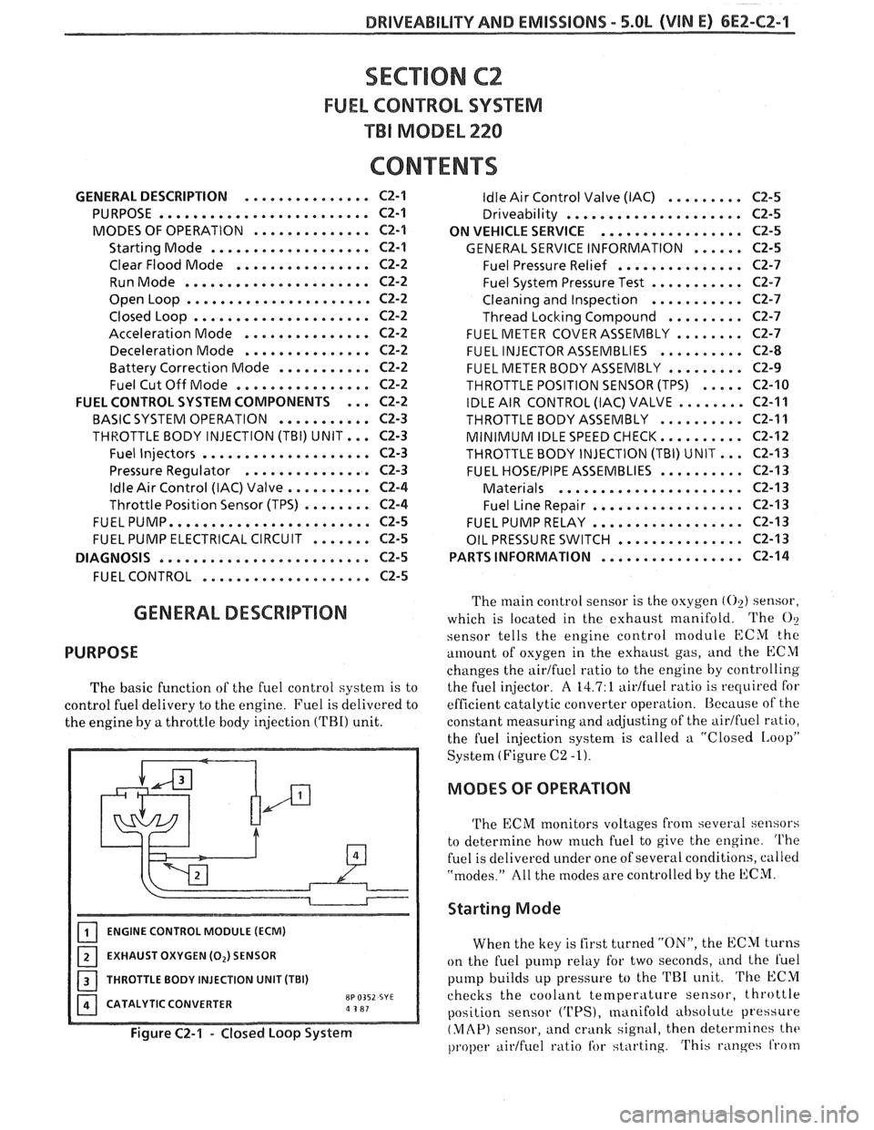
The basic function of the fuel control system is to
control fuel delivery to the engine. Fuel is delivered to
the engine by
a throttle body injection ('FBI) unit.
ENGINE CONTROL MODULE (ECM)
EXHAUST OXYGEN (0,) SENSOR
I 1 THROTTLE BODY INJECTION UNIT (TBI)
CATALYTIC CONVERTER
8P 0352 SYE a 3 81
Figure C2-1 - Closed Loop System
ldle Air Control Valve (IAC) . . . . . . . . . C2-5
Driveability . . . . . . . . . . . . . . . . . . . .. C2-5
ON VEHICLE SERVICE
. . . . . . . . . . . . . . . . . C2-5
GENERAL SERVICE INFORMATION . . . . . . C2-5
Fuel Pressure Relief . . . . . . . . . . . . . . . C2-7
Fuel System Pressure Test . . . . . . . . . . . C2-7
Cleaning and Inspection . . . . . . . . . . . C2-7
Thread Locking Compound . . . . . . . . . C2-7
FUEL METER COVER ASSEMBLY . . . . . . . . C2-7
FUEL INJECTOR ASSEMBLIES . . . . . . . . . . C2-8
FUEL METER BODY ASSEMBLY . . . . . . . . . C2-9
THROTTLE POSITION SENSOR (TPS) . . . . . C2-10
IDLE AIR CONTROL (IAC) VALVE . . . . . . . . C2-11
THROTTLEBODYASSEMBLY .......... C2-11
MINIMUM IDLE SPEED CHECK.. . . . . . . . . C2-12
THROTTLE BODY INJECTION (TBI) UNIT.. . C2-I3
FUEL HOSEIPIPE ASSEMBLIES . . . . . . . . . . C2-13
Materials . . . . . . . . . . . . . . . . . . . . . . C2-13
Fuel Line Repair . . . . . . . . . . . . . . . . . . C2-13
FUEL PUMP RELAY . . . . . . . . . . . . . . . . . . C2-13
OIL PRESSURE SWITCH . . . . . . . . . . . . . . . C2-13
PARTS INFORMATION
. . . . . . . . . . . . . . . . . C2-14
The main control sensor is the oxygen (02) sensor,
which is located in the exhaust manifold. The
O?
sensor tells
the engine control module ECM the
amount of osygen in the exhttust gas, and the ECM
changes the airtfuel ratio to the engine by controlling
the fuel injector.
A 14.7: 1 aidfuel ratio is required for
efficient catalytic converter operation. Because of the
constant measuring and adjusting of the
airlfuel ratio,
the fuel injection system is called a "Closed
IAoopP
System (Figure C2 -1).
MODES OF OPERATION
The ECM monitors voltages from several sensors
to determine how
much fuel to give the engine. The
fuel is delivered under one of several conditions, called
"modes." All the modes are controlled by the ECM.
Starting Mode
When the key is first turned "ON", the ECM turns
on the fuel pump relay for two seconds,
i~nd the l'uel
pump builds up pressure to the TRI unit. The ECM
checks the coolant
temperature sensor, throttle
position sensor
('UPS), manifold absolute pressure
(MAP) sensor, and crank signal, then determines the
proper airtfuel ratio tbr starting. This ranges from
Page 580 of 1825
DRIVEABILITY AND EMISSIONS - 5.OL (\/IN El 6EZ-CZ-5
sent to the ECM. The ECM then increases the injector
base pulse width, permitting increased fuel flow.
As the throttle valve rotates in response to
movement of the accelerator pedal, the throttle shaft
transfers this rotational movement to the
'I'PS. A
potentiometer (variable resistor) within the TPS
assembly changes its resistance (and voltage drop) in
proportion to throttle movement.
By applying a reference voltage (5.0 volts) to the
TPS input, a varying voltage (reflecting throttle
position) is available at the TPS output. For example,
approximately 2.5 volts results from a 50% throttle
valve opening (depending on TPS calibration). The
voltage output from the TPS assembly is routed to the
ECM for use in determining throttle position.
FUEL PUMP
The fuel pump is a turbine type, low pressure
electric pump, mounted in the fuel tank. Fuel
is
pumped at a positive pressure (above 62
kPa or 9 psi)
from the fuel pump through the in-line filter to the
pressure regulator in the TBI assembly Excess
fuel is
returned to the fuel tank through the fuel return line.
The fuel pump is attached to the fuel gage sender
assembly. A fuel strainer is attached to the fuel pump
inlet line and prevents dirt particles from entering the
fuel line and tends to separate
water from the fuel
Vapor lock problems are reduced when using an
electric
pump because the fuel is pushed from the tank
under pressure rather than being pulled
under
vacuum, a condition that produces vapor.
An inoperative fuel pump would cause
a. no start
condition. A fuel pump which does not provide enough
pressure can result in poor performance. (See "Fuel
System Pressure Test" procedure).
FUEL PUMP ELECTRICAL CIRCUIT
When the key is first turned "ON" without the
engine running, the ECM turns the
Fuel pump relay
"ON" for two seconds. This builds
up the fuel pressure
quickly. If the engine is not started within two
seconds, the
ECM shuts the fuel pump "OFF" and
waits until the engine starts. As soon as the engine is
cranked, the ECM turns the relay
"ON" and runs the
fuel pump.
As a backup system to the fuel pump relay, the
fuel pump can also be turned on
by the oil pressure
switch. The oil pressure sender has two circuits
internally. One operates the oil pressure indicator or
gage in the instrument cluster,
itnd the other is
anormally open switch which closes when oil pressure
reaches about 28
kPa (4 psi). If the fuel pump relay
fails, the oil pressure switch will run the fuel pump. An
inoperative fuel pump relay can result in long
cranking times, particularly if the engine is cold. The
oil pressure switch will turn on the fuel pump as soon
as oil pressure
reaches about 28 kPa (4 psi).
FUEL CONTROL
Always start with the "Diagnostic Circuit Check"
in Section
"6E2-A". This will reduce diagnosis time
and prevents unnecessary replacement of parts. The
information in this check will direct diagnosis
concerning "Engine
Crunlis But Won't Run" and the
"Fuel Control System," Section
"6E2-C2", including
diagnosis of an injector, pressure regulator,
fuel pump,
fuel
pump relay, and oil pressure switch.
Idle Air Control (IAC) Valve
A "Scan" tool reads IAC position in steps, calletl
"Counts." "0" steps indicates the ECM is commanding
the
IAC to be driven in, to a fully seiltetl position
(minimum idle air).
The higher the number steps, the
more idle air being allowed to pass
by the IAC valve.
cnose Refer to CHART C-2C for information to cliil,
the function of the IAC valve.
Driva bility
Refer to Section "B" for driveability symptoms
related to the fuel control.
ON-VEHICLE SERVICE
GENERAL SEWVICE INFORMATION
CAUTION:
e To prevent personal injury or damage to the
vehicle
as the result sf an accidental start,
disconnect and reconnect the negative
battery cable before and after service is
performed.
@ Also, catch any fuel that leaks out when
disconnecting the fuel lines, by covering the
fittings with
a shop cloth. Place the cloth in
an approved container when work is
complete.
The 'FBI unit repair procedures cover component
replacement with the unit on the vehicle,
tIowever,
throttle body replacement requires that the complete
unit
be removed from the enginc.
Page 725 of 1825
6E3-C1-6 2.8L (VIM O) DRlVEABlLlTY AND EMISSIONS
amportant
When replacing the production ECM with a
service ECM (controller), it is important to
transfer the Broadcast code and production
ECM number to the service ECM label. Please
do not record on ECM cover. This will allow
positive identification of ECM parts
throughout the service life of the vehicle.
amportant
To prevent internal ECM damage, the ignition
must be "OFF" when disconnecting or
reconnecting power to ECM (for example,
battery cable, ECM pigtail, ECM fuse, jumper
cables,
etc.).
ECM AND COMPONENTS REPLACEMENT
PROM OR ECM
Code 51 indicates a faulty PROM, possibly caused
by bent pins, or incorrect installation.
mmportant
It is possible to install a PROM backwards. If the
PROM
is installed backwards and the ignition key
turned to "ON," the PROM circuitry will be destroyed,
requiring PROM replacement.
NOTICE: The ignition should always be off when
installing or removing the ECM
connectors or internal components.
memove or Disconnect
1. Negative battery cable.
2. Right hand hush panel.
3. Connectors from ECM.
4. ECM mounting hardware.
5. ECM from passenger compartment.
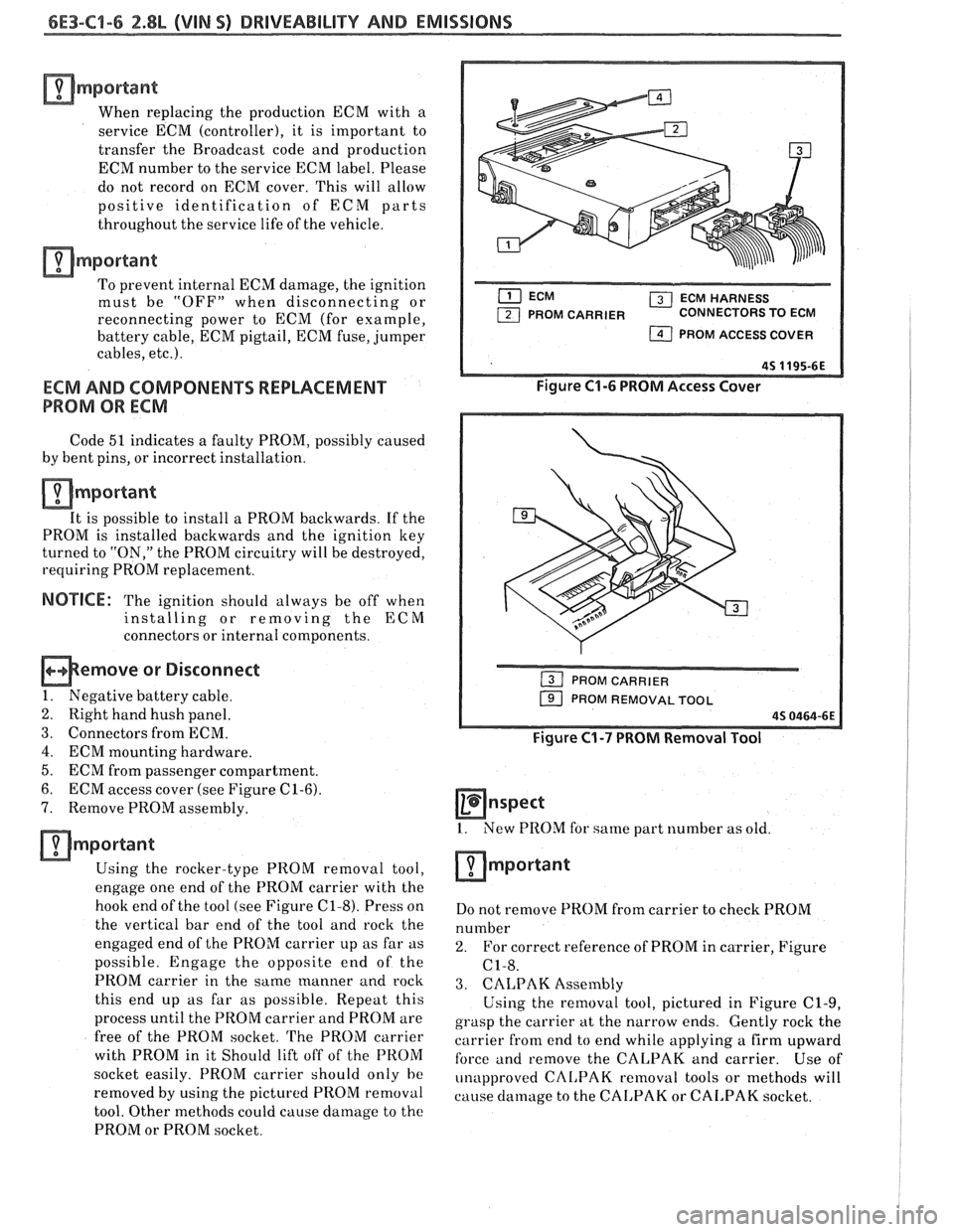
6. ECM access cover (see Figure
C1-6).
7. Remove PROM assembly.
amportant
Using the rocker-type PROM removal tool,
enga& one end of t-hk PROM carrier with the
hook end of the tool (see Figure
C1-8). Press on
the vertical bar end of the tool and rock the
engaged end of the PROM carrier up as far as
possible. Engage the opposite end of the
PROM carrier in the same manner and
rock
this end up as far as possible. Repeat this
process until the PROM carrier and PROM are
free of the PROM socket.
The PROM carrier
with PROM in it Should lift off of the PROM
socket easily. PROM carrier should only
he
removed by using the pictured PROM removal
tool. Other methods could cause damage to the
PROM or PROM socket.
( ECM HARNESS
PROM CARRIER CONNECTORS TO ECM
1 PROM ACCESS COVER
Figure C1-6 PROM Access Cover
PROM CARRIER
PROM REMOVAL TOOL
Figure C1-7 PROM Removal Tool
Hnspect
1. New PROM for same part number as old.
Do not remove PROM from carrier to check PROM
number
2. For correct reference of PROM in carrier, Figure
C1-8.
3. CALPAK Assembly
Using the removal tool, pictured in Figure C1-9,
grasp the carrier
at the narrow ends. Gently rock the
carrier
from end to end while applying a firm upward
force and remove the CALPAK and carrier. Use of
unapproved
CAL,PAK removal tools or methods will
cause
damage to the CAI,PAK or CALPAK socket.
Page 966 of 1825
DRIVEABILITY AND EMISSIONS - FUEL INJECTION 6E-5
TERMINAL IDENTIFICATION
GROUND SERIALDATA
(SEE SPECIAL TOOLS)
DIAGNOSTIC TERMINAL
I.I.R. (IF USED) T.C.C. (IF USED)
SERVICE
ENGINE FUEL PUMP (IF USED)
SOON LAMP- IF USED
SERIAL DATA (IF USED) 3-29-86 *6S 2615-6E (SEE SPECIAL TOOLS)
Figure 2 - ALDL Connector
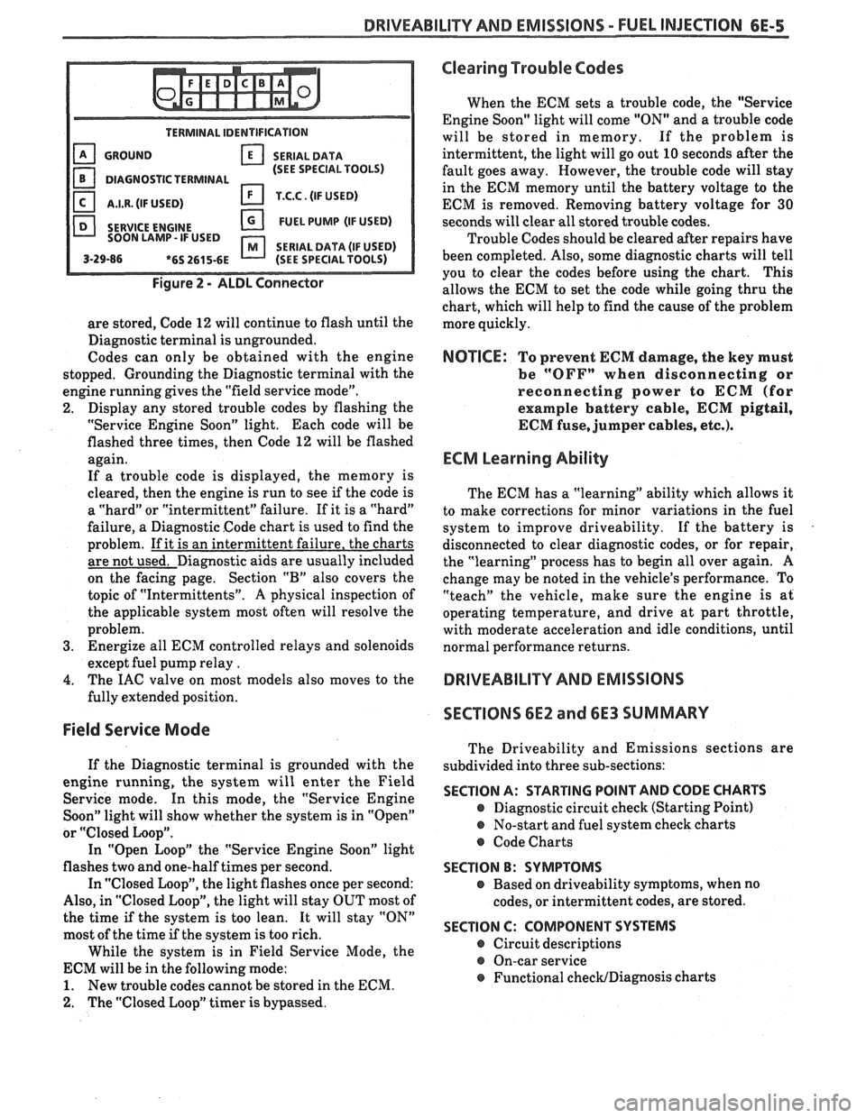
are stored, Code 12 will continue to flash until the
Diagnostic terminal is ungrounded.
Codes can only be obtained with the engine
stopped. Grounding the Diagnostic terminal with the
engine running gives the "field service mode".
2. Display any stored trouble codes by flashing the
"Service Engine Soon" light. Each code will be
flashed three times, then Code
12 will be flashed
again.
If a trouble code is displayed, the memory is
cleared, then the engine is run to see
if the code is
a "hard" or "intermittent" failure. If it is a "hard"
failure, a Diagnostic Code chart is used to find the
problem. If it is an intermittent failure, the charts
are not used. Diagnostic aids are usually included
on the facing page. Section
"B" also covers the
topic of "Intermittents".
A physical inspection of
the applicable system most often will resolve the
problem.
3. Energize all ECM controlled relays and solenoids
except fuel pump relay
.
4. The IAC valve on most models also moves to the
fully extended position.
Field Service Mode
If the Diagnostic terminal is grounded with the
engine running, the system will enter the Field
Service mode. In this mode, the "Service Engine
Soon" light will show whether the system is in "Open"
or
"Closed Loop".
In "Open Loop" the "Service Engine Soon" light
flashes two and one-half times per second.
In "Closed Loop", the light flashes once per second:
Also, in "Closed Loop", the light will stay OUT most of
the time
if the system is too lean. It will stay "ON"
most of the time if the system is too rich.
While the system is in Field Service Mode, the
ECM will be in the following mode:
1. New trouble codes cannot be stored in the ECM.
2. The "Closed Loop" timer is bypassed.
Clearing Trouble Codes
When the ECM sets a trouble code, the "Service
Engine Soon" light will come "ON" and a trouble code
will be stored in memory. If the problem is
intermittent, the light will go out
10 seconds after the
fault goes away. However, the trouble code will stay
in the ECM memory until the battery voltage to the
ECM is removed. Removing battery voltage for
30
seconds will clear all stored trouble codes.
Trouble Codes should be cleared after repairs have
been completed. Also, some diagnostic charts will tell
you to clear the codes before using the chart. This
allows the ECM to set the code while going thru the
chart, which will help to find the cause of the problem
more quickly.
NOTICE: To prevent ECM damage, the key must
be
"OFFn when disconnecting or
reconnecting power to
ECM (for
example battery cable,
ECM pigtail,
ECM fuse, jumper cables, etc.).
ECM Learning Ability
The ECM has a "learning" ability which allows it
to make corrections for minor variations in the fuel
system to improve driveability. If the battery is
disconnected to clear diagnostic codes, or for repair,
the "learning" process has to begin all over again.
A
change may be noted in the vehicle's performance. To
"teach" the vehicle, make sure the engine is at
operating temperature, and drive at part throttle,
with moderate acceleration and idle conditions, until
normal performance returns.
DRIVEABILITY AND EMISSIONS
SECTIONS
6E2 and 6E3 SUMMARY
The Driveability and Emissions sections are
subdivided into three sub-sections:
SECTION A: STARTING POINT AND CODE CHARTS
@ Diagnostic circuit check (Starting Point)
@ No-start and fuel system check charts
@ Code Charts
SECTION B: SYMPTOMS
e Based on driveability symptoms, when no
codes, or intermittent codes, are stored.
SECTION C: COMPONENT SYSTEMS
@ Circuit descriptions
@ On-car service
@ Functional checWDiagnosis charts
Page 1050 of 1825

TORQUE CONVERTER CLUTCH (TCC)
DIAGNOSIS
To properly diagnose the Torque Converter
Clutch (TCC) system, perform all electrical
testing first and then the hydraulic testing. Refer
to the Torque Converter Section
6E2-C8 for
additional information.
The TCC is applied by fluid pressure which is
controlled by a solenoid located inside the Automatic
Transmission assembly. The solenoid is energized or
released by making or breaking an electrical circuit
through a combination of switches and sensors.
TCC Electrical Diagnosis
e For electrical diagnosis of TCC, refer to the
specific vehicle section in Section
8A, Electrical
Diagnosis.
e For diagnosis of emission control related
components of TCC, Refer to the specific section
of
6E, Driveability and Emissions.
e For the diagnosis of TCC Hydraulic Controls,
refer to the Procedure and Wiring Diagrams
provided in this section.
Functional Check Procedure
rn Inspect
1. Install a tachometer
2. Operate the vehicle until proper operating
temperature is reached
3. Drive vehicle at 50-55 mph (80-88 Km/h) with
light throttle (road load)
4. Maintaining throttle lightly touch the brake
pedal and check for a slight bump when the TCC
releases and a slight increase in engine RPM.
5. Release the brake, slowly accelerate and check for
a re-apply of the converter clutch and a slight
decrease in engine RPM.
Preliminary Checking Procedure
The purpose of the preliminary checking
procedure is to isolate external (electrical) problems
from internal (electrical or mechanical) ones.
Important
e Use only a scale type ohmmeter. High impedance
type ohmmeters and those with a digital readout
will not work.
e An ALCL scanner may be used to verify the
electrical circuit. Remember, a completed circuit
does not indicate that the solenoid will apply.
e Do not bench test using an automotive type
battery. Accidentally crossed wires will damage
the internal diodes of the TCC solenoid.
HYDRAULIC DIAGNOSIS 700-R4-61
External Controls
rn Inspect
e Connect voltmeter between transmission
connector and ground.
e Turn key "ON"
e If 0 or low voltage is found, refer to Sections 6E
and 8A for electrical diagnosis.
e If 12 volts are present at the connector, refer to
the TCC hydraulic diagnosis.
TORQUE CONVERTER EVALUATION
Torque Converter Stator
The Torque Converter Stator roller clutch can
have one of two different type malfunctions:
A. Stator Assembly freewheels in both
directions.
B. Stator Assembly remains locked up at all
times.
Condition A-Poor Acceleration Low Speed
The vehicle tends to have poor acceleration from
a standstill. At speeds above 30-35 mph (50-55
km/h),
the car may act normal. If poor acceleration is noted,
it should first be determined that the exhaust system
is not blocked, the engine timing is correct and the
transmission is in first
(1st) gear when starting out.
If the engine freely accelerates to high
r.p.m. in
"NEUTRAL" (N), it can be assumed that the engine
and exhaust system are normal. Checking for poor
performance in "Drive" and Reverse will help
determine if the stator is freewheeling at all times.
Condition B-Poor Acceleration High Speed
Engine r.p.m. and car speed limited or restricted
at high speeds. Performance when accelerating from a
standstill is normal. Engine may over-heat. Visual
examination of the converter may reveal a blue color
from over-heating.
If the converter has been removed, the stator
roller clutch can be checked by inserting a finger into
the splined inner race of the roller clutch and trying to
turn the race in both directions. The inner race should
turn freely clockwise, but not turn or be very difficult
to turn counterclockwise.
The Converter Should Be Replaced If:
e Leaks externally, such as at the hub weld area.
e Converter has an imbalance which cannot be
corrected. (Refer to Converter Vibration Test
Procedure).
e Converter is contaminated with engine coolant
containing antifreeze.
The Converter Should Not Be Replaced If:
e The oil has an odor, is discolored, and there is no
evidence of metal or clutch facing particles.
e The threads in one or more of the three converter
bolt holes are damaged.
- Correct with thread insert. (Refer to Section
6A).
Page 1123 of 1825
7A44 AUTOMATIC "PANSMISSION ON-VEHICLE SERVICE
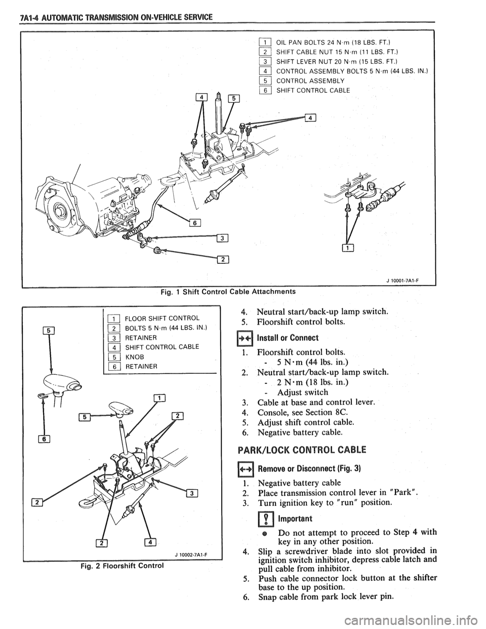
Fig. 1 Shift Control Cable Attachments
4. Neutral starthack-up lamp switch.
5. Floorshift control bolts.
Install or Connect
1. Floorshift control bolts.
- 5 N-m (44 lbs. in.)
2. Neutral starthack-up lamp switch.
- 2 N.m (18 lbs. in.)
- Adjust switch
3. Cable at base and control lever.
4. Console, see Section 8C.
5. Adjust shift control cable.
6. Negative battery cable.
PARK/LOCK CONTROL CABLE
Remove or Disconnect (Fig. 3)
1. Negative battery cable
2. Place transmission control lever in "Park".
3. Turn ignition key to "run" position.
Important
s Do not attempt to proceed to Step 4 with
key in any other position.
4. Slip a screwdriver blade into slot provided in
ignition switch inhibitor, depress cable latch and
pull cable from inhibitor.
5. Push cable connector lock button at the shifter
base to the up position.
6. Snap cable from park lock lever pin.
Page 1124 of 1825
AUTOMATIC TMNSMISSION ON-VEHICLE SERVICE 7A1-5
7. Depress two cable connector latches and remove
from shifter base.
8. Cable clips
Install or Connect
1. With cable lock button in the up position and
shift lever in the "Park" position, snap cable
connector into shifter base.
2. With ignition key in "run" position; snap cable
into inhibitor housing.
Important
e Do not attempt to insert cable with key in
any other position.
3. Turn ignition key to "Lock".
4. Snap cable end onto shifter park lock lever pin.
5. Push cable connector hose forward to remove
slack.
6. With no load applied to connector nose, snap
cable connector lock button down.
Inspect
Functional Operation
1. With the shift lever in "Park" and the key
in "Lock" position, make sure that you
cannot move the shifter lever to another
position. Ignition key should be removable
from column.
2. With the key in "run" and the shift lever in
"Neutral", make sure that you cannot turn
the key to "Lock".
3. If the above conditions are met, the system
is properly adjusted. Proceed to Step
5.
4. If the above conditions are not met, put
cable connector lock back to the up position
and readjust as indicated in Steps
5 and 6
above, then push cable connector lock
button down and recheck operation.
5. If key cannot be removed in "Park"
position, snap connector lock button to up
position and move cable connector nose
rearward until key can be removed from
ignition.
6. Snap lock button down.
7. Reinstall cable into clips to provide correct
routing.
PARK/NEUTRAL AND BACK-UP LAMP
SWITCH
Remove or Disconnect (Fig. 4)
1. Negative battery cable.
2. Console, see Section 8C.
3. Mounting bolts.
4. Switch
Using Old Switch
Install or Connect :
1. Place shift control lever shaft in "NEUTRAL" Align
carrier tang on switch with tang slot on
shift control.
Assemble mounting bolts-to-case, loosely.
Rotate switch to align service adjustment hole
with carrier tang hole.
Insert gage pin
(2.34mm/3/32") in service
adjustment hole and rotate switch until pin drops
in to a depth of 15 mm
(19/32").
Torque bolts.
- 2 N.m (1 8 lbs. in.).
Gage pin
Console, see Section
8C.
Negative battery cable.
Important
After switch adjustment, verify that engine
will only start in
"PARK" or
"NEUTRAL". If engine will start in any
other position readjust switch.
Using New Switch
Install or Connect
1. Place shift control lever in "NEUTRAL".
2. Insert carrier tang on switch in slot on shifter.
3. Mounting bolts and torque.
- 2 N-m (18 lbs. in.)
If bolt holes do not align with shift control verify
shift control lever is in "NEUTRAL" position,
do not rotate switch. Switch is pinned in
"NEUTRAL" position.
e If switch has been rotated and pin broken,
switch can be adjusted by using the Using
Old Switch" procedure.
4. Move shift control lever out of ""Neutral"
position to shear plastic pin.
Important
After switch installation verify that engine
will only start in "PARK" and
"NEUTRAL". If engine will start in any
other position, readjust switch using "Old
Switch" procedure.
5. Console, see Section
8C.
6. Negative battery cable.
T.V. CABLE
The T.V. cable used on the 700-R4 transmission
controls line pressure, shift points, shift feel, part
throttle downshifts and detent downshifts. The T.V.
cable operates the throttle valve lever
anu bracket
assembly in the control valve.
The Throttle Valve Lever and Bracket Assembly
serves two
(2) basic functions:
1. To
transfer the throttle lever movement to the
T.V. plunger in the control valve assembly. This
causes T.V. pressure and line pressure to increase
according to engine throttle
openiq : and controls
part throttle and detent downshifts.
2. To prevent the transmission from operating at
low (idle) pressures, if the
T.V. cable should
Page 1514 of 1825
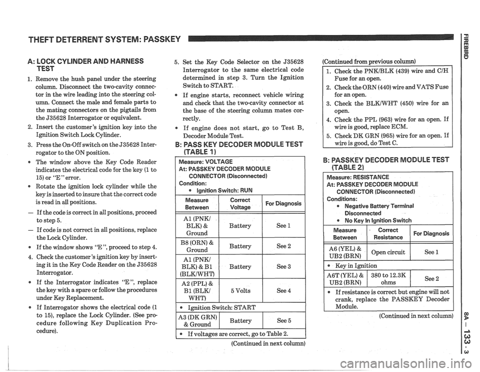
THEFT DETERRENT SYSTEM: PASSKEY I i
A: LOCK CYLINDER AND HARNESS
TEST
1. Remove the hush panel under the steering
column. Disconnect the two-cavity connec-
tor in the wire leading into the steering col-
umn. Connect the male and female parts to
the mating connectors on the pigtails from
the 535628 Interrogator or equivalent.
2. Insert the customer's ignition key into the
Ignition Switch Lock Cylinder.
3. Press the On-Off switch on the 535628 Inter-
rogator to the ON position.
* The window above the Key Code Reader
indicates the electrical code for the key
(1 to
15) or
"En error.
Rotate the ignition lock cylinder while the
key is inserted to insure that the correct code
is read in all positions.
- If the code is correct in all positions, proceed
to step 5.
- If code is not correct in all positions, replace
the Lock Cylinder.
* If the window shows "E ", proceed to step 4.
4. Check the customer's ignition key by insert-
ing it in the Key Code Reader on the 535628
Interrogator.
If the Interrogator indicates
"EM, replace
the key with a spare or follow the procedures
under Key Replacement.
If Interrogator shows the electrical code
(1
to 15), replace the Lock Cylinder. (See pro-
cedure following Key Duplication Pro-
cedure). 5.
Set the Key Code Selector on the 535628
Interrogator to the same electrical code
determined in step 3. Turn the Ignition
Switch to START.
If engine starts, reconnect vehicle wiring
and check that the two-cavity connector at
the base of the steering column mates cor-
rectly.
If engine does not start, go to Test B,
Decoder Module Test.
B: PASS KEY DECODER MODULE TEST
(TABLE
1 )
At: PASSKEY DECODER MODULE
CONNECTOR (Disconnected)
Condition:
1 . 1mition switch: START I
Ignition Switch: RUN
Continued from previous c
1. Check the PNKIBLK (439) wire and ClN
Fuse for an open.
2. Check the ORN (440) wire and VATS Fuse
for an open.
3. Check the
BLKIWT (450) wire for an
open.
4. Check the PPL (963) wire for an open.
If
wire is good, replace ECM.
5. Check DK GRN (965) wire for an open. If
wire is good, do Test C.
For Diagnosis
See 1
See 2
See 3
See 4
Measure
Between
A1 (PNKI
BLK) &
Ground
(ORN' &
Ground
A1 (PNKI
BLK)
& I31
(BLKIWNT)
A2 (PPL) &
Bl (BLKI
WNT)
B: PASSKEY DECODER MODULE TEST
Correct
Voltage
Battery
Battery
Battery
5 Volts
(TABLE 2)
Measure: RESISTANCE
At: PASSKEY DECODER MODULE
CONNECTOR (Disconnected)
Conditions: Negative Battery Terminal
Disconnected
r No lCev ln lainition Switch
Measure
- Correct For Diagnosis
Between Resistance
& open circuit
UB2 (BRN) See 1
crank,
replace the PASSKEY Decoder
Module.
-
(Continued in next column) A3 (DK GRN)
& Ground
I . If voltages are correct, go to Table 2.
(Continued in next column)
Battery See 5