PONTIAC G5 2010 Owners Manual
Manufacturer: PONTIAC, Model Year: 2010, Model line: G5, Model: PONTIAC G5 2010Pages: 422, PDF Size: 2.22 MB
Page 301 of 422

5. Check that the jumper cables do not have loose ormissing insulation. If they do, you could get a
shock. The vehicles could be damaged too.
Before you connect the cables, here are some
basic things you should know. Positive (+) will go to
positive (+) or to a remote positive (+) terminal if
the vehicle has one. Negative ( −) will go to a heavy,
unpainted metal engine part or to a remote
negative (−) terminal if the vehicle has one.
Do not connect positive (+) to negative ( −)oryou
will get a short that would damage the battery
and maybe other parts too. And do not connect the
negative (−) cable to the negative ( −) terminal on
the dead battery because this can cause sparks.
6. Connect the red positive (+) cable to the positive (+) terminal location on the vehicle with the dead
battery. Use a remote positive (+) terminal if the
vehicle has one.
7. Do not let the other end touch metal. Connect it to the positive (+) terminal of the good battery. Use a
remote positive (+) terminal if the vehicle has one. 8. Now connect the black negative (
−) cable to the
negative (−) terminal of the good battery. Use a
remote negative ( −) terminal if the vehicle has one.
Do not let the other end touch anything until the
next step. The other end of the negative ( −) cable
does not go to the dead battery. It goes to a
heavy, unpainted metal engine part or to a remote
negative (−) terminal on the vehicle with the
dead battery.
9. Connect the other end of the negative ( −) cable to
the negative (−) terminal location on the vehicle with
the dead battery. Your vehicle has a remote
negative (−) terminal marked GND ( −).
10. Now start the vehicle with the good battery and run the engine for a while.
11. Try to start the vehicle that had the dead battery. If it will not start after a few tries, it probably needs
service.
6-37
Page 302 of 422

Notice:If the jumper cables are connected or
removed in the wrong order, electrical shorting may
occur and damage the vehicle. The repairs would
not be covered by the vehicle warranty. Always
connect and remove the jumper cables in the correct
order, making sure that the cables do not touch
each other or other metal.
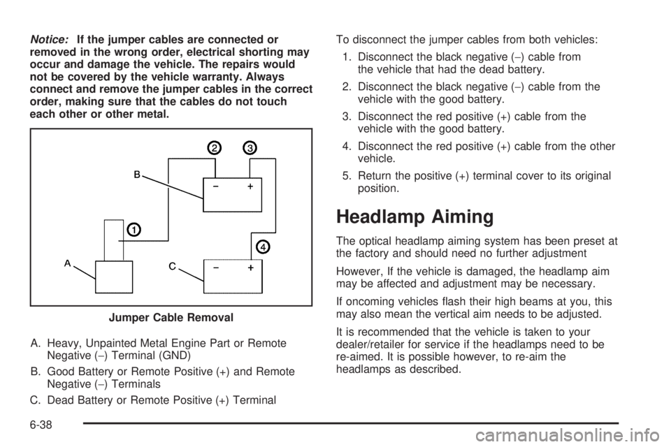
A. Heavy, Unpainted Metal Engine Part or Remote Negative (−) Terminal (GND)
B. Good Battery or Remote Positive (+) and Remote Negative (−) Terminals
C. Dead Battery or Remote Positive (+) Terminal To disconnect the jumper cables from both vehicles:
1. Disconnect the black negative ( −) cable from
the vehicle that had the dead battery.
2. Disconnect the black negative ( −) cable from the
vehicle with the good battery.
3. Disconnect the red positive (+) cable from the vehicle with the good battery.
4. Disconnect the red positive (+) cable from the other vehicle.
5. Return the positive (+) terminal cover to its original position.
Headlamp Aiming
The optical headlamp aiming system has been preset at
the factory and should need no further adjustment
However, If the vehicle is damaged, the headlamp aim
may be affected and adjustment may be necessary.
If oncoming vehicles flash their high beams at you, this
may also mean the vertical aim needs to be adjusted.
It is recommended that the vehicle is taken to your
dealer/retailer for service if the headlamps need to be
re-aimed. It is possible however, to re-aim the
headlamps as described.
Jumper Cable Removal
6-38
Page 303 of 422

The vehicle should be:
•Placed so the headlamps are 25 ft. (7.6 m) from a
light colored wall.
•On a perfectly level surface which is level all the
way to the wall.
•Placed so it is at a right angle to the wall.
•Clear of any snow, ice, or mud on it.
•Fully assembled, with the tires properly inflated, and
all other work stopped while headlamp aiming is
being done.
•Normally loaded with a full tank of fuel, with the
spare tire in the proper location, and one person
or 160 lbs (75 kg) on the driver seat.Headlamp aiming is done with the vehicle’s low-beam
headlamps. The high-beam headlamps will be correctly
aimed if the low-beam headlamps are aimed properly.
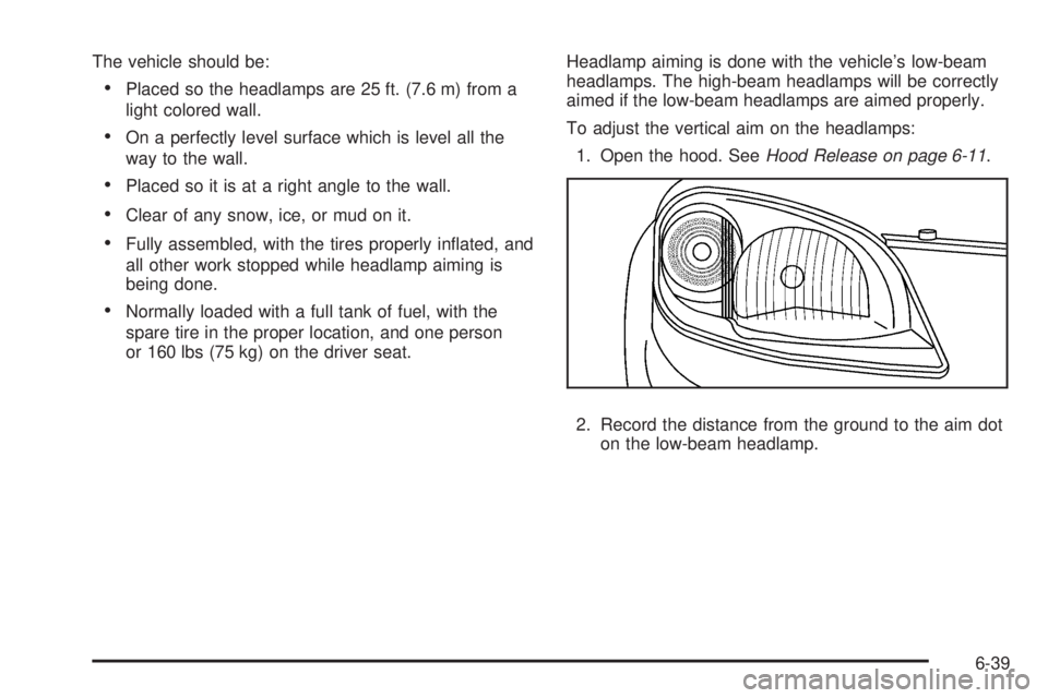
To adjust the vertical aim on the headlamps:
1. Open the hood. See Hood Release on page 6-11 .
2. Record the distance from the ground to the aim dot on the low-beam headlamp.
6-39
Page 304 of 422

3. At the wall, measure from the ground upward (A) tothe recorded distance from Step 2 and mark it.
4. Draw or tape a horizontal line (B) on the wall the width of the vehicle at the height of the mark in
Step 3.
Notice: Do not cover a headlamp to improve beam
cut-off when aiming. Covering a headlamp may
cause excessive heat build-up which may cause
damage to the headlamp.
5. Turn on the low-beam headlamps and place a piece of cardboard in front of the headlamp not
being adjusted. Do not place it directly on the
headlamp. This allows only the beam of light from
the headlamp being adjusted to be seen on the
flat surface. 6. Locate the vertical headlamp aiming screws, which
are under the hood near each headlamp assembly.
The adjustment screw can be turned with a 6 mm
socket wrench.
7. Turn the vertical aiming screw until the headlamp beam is aimed to the horizontal tape line. Turn it
clockwise or counterclockwise to raise or lower the
angle of the beam.
6-40
Page 305 of 422

8. Make sure that the light from the headlamp ispositioned at the bottom edge of the horizontal tape
line. The lamp on the left (A) shows the correct
headlamp aim. The lamp on the right (B) shows the
incorrect headlamp aim.
9. Repeat Steps 6 through 8 for the opposite headlamp.
Bulb Replacement
For the proper type of replacement bulbs, see
Replacement Bulbs on page 6-47 .
For any bulb changing procedure not listed in this
section, contact your dealer/retailer.
Halogen Bulbs
{WARNING:
Halogen bulbs have pressurized gas inside and
can burst if you drop or scratch the bulb. You or
others could be injured. Be sure to read and follow
the instructions on the bulb package.
6-41
Page 306 of 422

Headlamps, Front Turn Signal,
Sidemarker, and Parking Lamps
A. Front Turn Signal/Parking Lamp
B. Sidemarker
C. Headlamp To replace one of these bulbs:
1. Open the hood. See Hood Release on page 6-11 .
2. Remove the two bolts from the headlamp assembly.
3. Remove the two fasteners from the fascia. Assistance may be needed for Steps 4 and 5.
4. Pull the front fascia back.
6-42
Page 307 of 422

5. Pull the headlamp assembly up at an angle andtowards the radiator to remove it.
6. Disconnect the bulb base from the wiring harness by lifting the locking tab.
7. Disconnect the wiring harness from the bulb socket.
8. Remove the retainer by turning it counterclockwise.
9. Turn the bulb socket for the headlamp, front turn signal, or parking lamp counterclockwise.
For the sidemarker bulb, use a tool to assist
in turning the bulb socket.
10. Pull the old bulb out of the socket.
11. Install a new bulb.
12. Reinstall the bulb assembly by reversing Steps 1 through 9.
When reinstalling the headlamp assembly, first
make sure that the wiring harness is in its original
position. If not, the headlamp assembly will not
fit correctly.
Align the two tabs on the bottom of the assembly
that fit into two slots in the headlamp assembly
bracket.Center High-Mounted Stoplamp
(CHMSL)
To replace a CHMSL bulb: 1. Open the trunk.
2. Press the tabs to release the bulb assembly.
3. Pull the bulb assembly down to access the bulbs.
4. Pull the old bulb straight out.
6-43
Page 308 of 422

5. Push the new bulb straight in until it clicks.
6. Align the tabs in the bulb assembly with theassembly in the trunk lid. Push the bulb assembly
back into place until it snaps in. You may need
to use a tool to guide the tabs into the assembly.
Taillamps and Turn Signal Lamps
(Coupe)
To replace a taillamp or rear turn signal bulb:
1. Open the trunk. See Trunk on page 3-11for more
information.
2. Remove the screw retaining the taillamp assembly.
3. Disconnect the wiring harness by lifting up on the tab to release and pull it straight out.
4. Hold and turn the bulb socket clockwise and then release it from the lamp housing.
5. Pull the old bulb straight out of the socket.
6. Install a new bulb.
7. Reverse Steps 2 through 4 to reinstall the taillamp assembly.
Taillamps, Turn Signal, Stoplamps
and Back-up Lamps (Sedan)
To replace one of these bulbs:
1. Open the trunk.
2. Remove the trunk trim and pull back fastener.
3. Remove the additional fastener.
4. Remove the outer two screws from the taillamp assembly.
5. Lift up on the tab and pull the wiring harness straight out.
6. Remove the taillamp assembly from the quarter panel.
6-44
Page 309 of 422

A. Sidemarker
B. Stoplamp/Turn Signal/Taillamp
C. Back-up
7. Turn the bulb socket counterclockwise and pull it straight out.
8. Pull the old bulb straight out of the socket.
9. Push the new bulb straight into the socket.
10. Push the new bulb into the taillamp assembly and turn it clockwise to lock it into place. 11. Reinstall the taillamp assembly into the quarter
panel.
12. Push the wiring harness straight into the taillamp assembly and push the tab down.
13. Reinstall the outer two screws into the taillamp assembly.
14. Reinstall the trunk trim and the fasteners.
Back-Up Lamps (Coupe)
To replace a back-up lamp bulb:
1. Remove the two screws from the face of the back-up lamp.
2. Pull the lamp straight out from the fascia pocket.
6-45
Page 310 of 422

3. Hold and turn the bulb socket clockwise and thenrelease it from the lamp housing.
4. Pull the old bulb out of the socket.
5. Push the new bulb straight into the bulb socket until it clicks.
6. Push the bulb socket into the housing and turn it clockwise to lock it into place.
7. Push the lamp straight into the fascia pocket.
8. Reinstall the two screws into the face of the back-up lamp.License Plate Lamp
To replace one of these bulbs:
1. Remove the two screws holding each of the license plate lamps.
2. Turn and pull the license plate lamp toward you through the opening.
3. Turn the bulb socket counterclockwise and pull the bulb straight out of the socket.
4. Install the new bulb.
5. Push the bulb straight into the socket and turn clockwise to reinstall.
6-46