PORSCHE 911 CARRERA 2005 5.G Owners Manual
Manufacturer: PORSCHE, Model Year: 2005, Model line: 911 CARRERA, Model: PORSCHE 911 CARRERA 2005 5.GPages: 282, PDF Size: 4.34 MB
Page 241 of 282
Practical Tips, Emergency Service
241
Installing the battery 1. Put battery in and push it all the way to the
stop.
2. Screw in fastening screw B.
Danger!
Risk of short circuit and explosion.
fImportant: connect the positive (+) cable first, and then the negative (–) ground wire.
3. Push on central vent hose C.
4. Fit plastic lid. Lock turn-locks A.
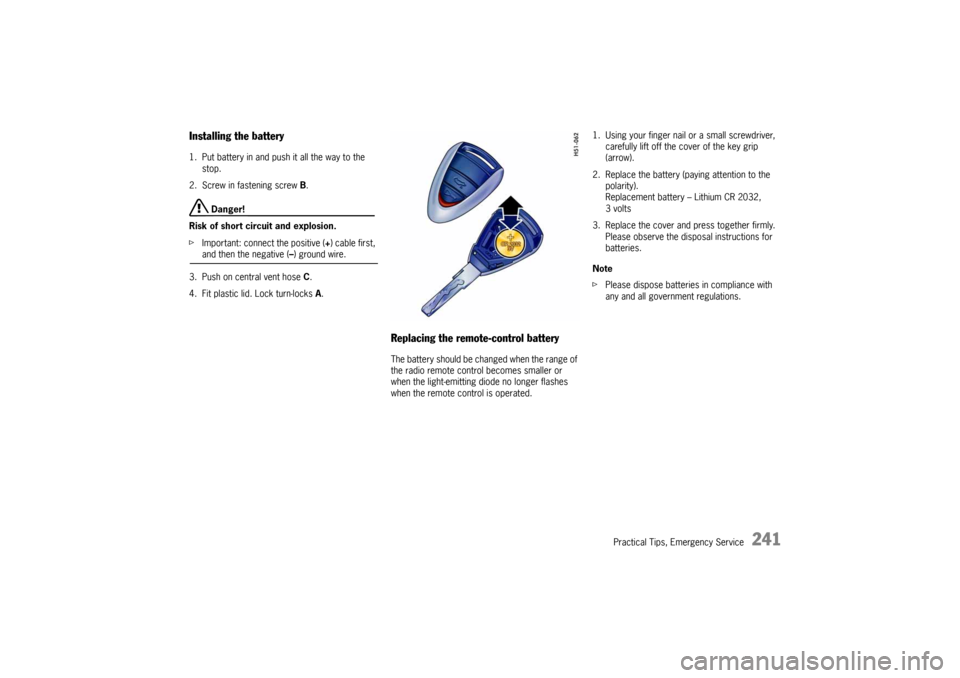
Replacing the remote-control battery The battery should be changed when the range of
the radio remote control becomes smaller or
when the light-emitting diode no longer flashes
when the remote control is operated.1. Using your finger nail or a small screwdriver,
carefully lift off the cover of the key grip
(arrow).
2. Replace the battery (paying attention to the
polarity).
Replacement battery – Lithium CR 2032,
3volts
3. Replace the cover and press together firmly.
Please observe the disposal instructions for
batteries.
Note
fPlease dispose batteries in compliance with
any and all government regulations.
Page 242 of 282

242
Practical Tips, Emergency Service
Emergency Starting with Jumper
Cables If the battery is discharged, e.g. in winter or after
the car has been parked for a long time, the bat-
tery of another car can be used for starting with
the help of jumper cables.
Make sure the voltage of both batteries is the
same. Both batteries must be 12 volt types.
The capacity (Ampere hours, Ah) of the booster
battery must not be substantially less than that of
the discharged battery.
The discharged battery must be correctly con-
nected to the vehicle’s electrical system.
fPlease observe the chapter “BATTERY” on
Page 236.
fPlease observe the chapter “EMERGENCY UN-
LOCKING OF THE LUGGAGE COMPARTMENT
LID” on Page 235.
Note
fDo not try to start the car by pushing or tow-
ing. Damage to the catalytic converters and
other components of the car may result.
Warning!
Risk of damage and serious personal injury
due to short circuit.
fUse only jumper cables of adequate diameter
cross-section and fitted with completely insu-
lated alligator clips.
fFollow all warnings and instructions of the
jumper cable manufacturer.
fWhen connecting jumper cables, make sure
that they cannot get caught in any moving
parts in the engine compartment.
The jumper cables must be long enough so
that neither vehicles nor cables touch another.
fThe vehicles must not be in contact, otherwise
current might flow as soon as the positive ter-
minals are connected.
fThe cable clamps must not be allowed to con-
tact each other when one end of the jumper ca-
bles are connected to a battery.
fEnsure that tools or conductive jewelery (rings,
chains, watch straps) do not come into contact
with the positive jumper cable or the positive
battery post.
fImproper hook-up of jumper cables can ruin
the alternator. Danger of caustic burns.
fDo not lean over the battery.
Danger of gas explosion.
fImproper use of booster battery to start a
vehicle may cause an explosion, resulting in
severe personal injuries.
fKeep sources of ignition away from the bat-
tery, e.g. open flame, burning cigarettes or
sparking due to cable contact or welding work.
fA discharged battery can freeze even at
23°F/–5°C.
Before connecting jumper cables, a frozen bat-
tery must be thawed out.
Page 243 of 282

Practical Tips, Emergency Service
243
Connect jumper cables in the following
sequence:
Always observe the sequence below:
1. Connect the positive lead (red) to the
positive terminal of the discharged battery
first, then connect it to the positive terminal of
the donor battery.
2. First connect the negative cable (black) to
the negative terminal of the donor battery, then
connect it to a suitable grounding point on the
vehicle with the discharged battery.
This grounding point must lie as far as possible
from the battery.
For example, a solid metal part or the engine
block are suitable grounding points.
If no suitable grounding points are to be found
on either vehicle, the negative cable must
carefully be connected directly to the negative
terminal of the battery.
If a suitable grounding point is to be found only
on the donor vehicle, the negative cable must
first be connected to the terminal of the
discharged battery, then to the grounding point
of the donor vehicle.
3. Run the engine of the donor car at a higher
speed.4. Start the engine.
An attempted start using jumper cables should
not last more than 15 seconds. Then allow a
waiting period of at least one minute.
Note
Before disconnecting the jumper cables, electrical
loads such as the heated rear window and the
heating fan blower should be switched on (the ve-
hicle’s lights must not be switched on). This reduc-
es voltage peaks which may occur when discon-
necting the jumper cables.
With the engine running, remove both jumper ca-
bles in reverse order.
Page 244 of 282
244
Practical Tips, Emergency Service
Lights, Replacing Bulbs
Warning!
Risk of short circuit.
fAlways switch off the relevant consumer when
changing bulbs.
Risk of injury. The Bi Xenon headlights are
under high voltage when installed.
fBe careful during all work in the area of the Bi
Xenon headlights.
Risk of damage. Bulbs of a higher wattage
can damage the lamp housing.
fOnly the bulbs shown in the chart may be used.
fNew bulbs must be clean and free from oil,
grease and fingerprints. Therefore, never
touch bulbs with your bare hands.
Use a cloth or soft paper while replacing bulbs.
Caution!
Risk of damage to headlights due to exces-
sive temperatures and abrasion.
fAttach no coverings (e.g. films, “stone
guards”) in the area of the headlights.
fUse soapy water only to clean light lenses and
plastic headlight lenses.
In no case may chemical cleaners or other vol-
atile cleaning fluids be used.
fTo prevent scratches, do not rub with a dry or merely moist cloth, tissue or insect sponges.
Page 245 of 282

Practical Tips, Emergency Service
245
Bulb chart
Ty p e , r a t i n g
Halogen low beam H7, 55W
Low beam with Bi-Xenon headlight Philips, D2S 35W
Halogen high beam H9, 65W
Additional high beam with Bi-Xenon headlight H11, 55W
Fog light H8, 35W
Tail light, rear fog light P21/4W
Brake light/tail light P21/4W
Tail light, reflector P21/5W
Make-up mirror light K3W
Reversing light P21
Trun signal indicator light, front and rear PY21W
Turn signal indicator light, side WY5W
Side marker light W3W
Door guard/Curb light W5W
Parking light W5W Blue-Vision
License plate light C5W
Luggage compartment/engine compartment
light, interior lightK10W
Reading light 6W Xenon
Page 246 of 282
246
Practical Tips, Emergency Service
Headlights
Caution!
Risk of damage to headlights due to abrasion
and excessive temperatures.
fDo not fix any coverings (e.g. “stone guards” or films) in the area of the headlights.
Note
The headlights can mist up depending on the
temperature and humidity.
fTo ensure optimum ventilation, do not cover
the gap between headlight and body
(e.g. “stone guards” or films).
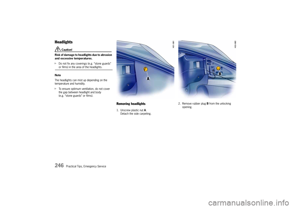
Removing headlights1. Unscrew plastic nut A.
Detach the side carpeting.2. Remove rubber plug B from the unlocking
opening.
Page 247 of 282
Practical Tips, Emergency Service
247
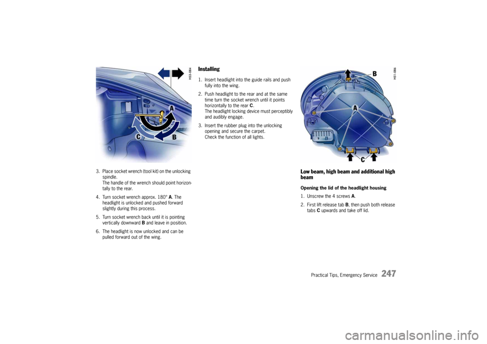
3. Place socket wrench (tool kit) on the unlocking
spindle.
The handle of the wrench should point horizon-
tally to the rear.
4. Turn socket wrench approx. 180° A. The
headlight is unlocked and pushed forward
slightly during this process.
5. Turn socket wrench back until it is pointing
vertically downward B and leave in position.
6. The headlight is now unlocked and can be
pulled forward out of the wing.
Installing1. Insert headlight into the guide rails and push
fully into the wing.
2. Push headlight to the rear and at the same
time turn the socket wrench until it points
horizontally to the rear C.
The headlight locking device must perceptibly
and audibly engage.
3. Insert the rubber plug into the unlocking
opening and secure the carpet.
Check the function of all lights.
Low beam, high beam and additional high
beamOpening the lid of the headlight housing
1. Unscrew the 4 screws A.
2. First lift release tab B, then push both release
tabs C upwards and take off lid.
Page 248 of 282
248
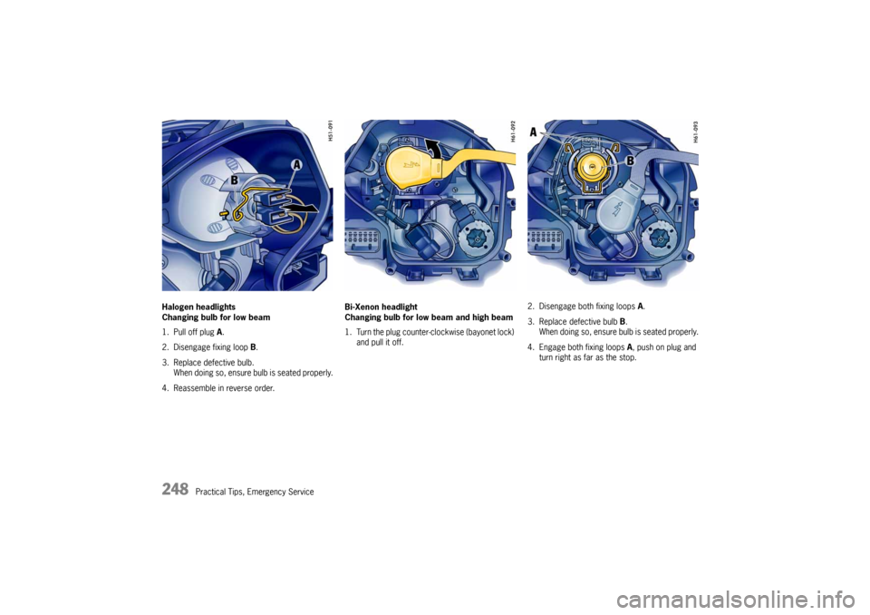
Practical Tips, Emergency Service Halogen headlights
Changing bulb for low beam
1. Pull off plug A.
2. Disengage fixing loop B.
3. Replace defective bulb.
When doing so, ensure bulb is seated properly.
4. Reassemble in reverse order.Bi-Xenon headlight
Changing bulb for low beam and high beam
1. Turn the plug counter-clockwise (bayonet lock)
and pull it off.2. Disengage both fixing loops A.
3. Replace defective bulb B.
When doing so, ensure bulb is seated properly.
4. Engage both fixing loops A, push on plug and
turn right as far as the stop.
Page 249 of 282
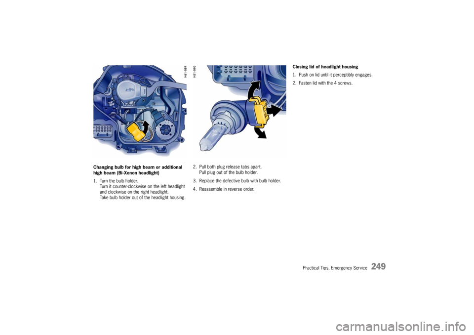
Practical Tips, Emergency Service
249
Changing bulb for high beam or additional
high beam (Bi-Xenon headlight)
1. Turn the bulb holder.
Turn it counter-clockwise on the left headlight
and clockwise on the right headlight.
Take bulb holder out of the headlight housing.2. Pull both plug release tabs apart.
Pull plug out of the bulb holder.
3. Replace the defective bulb with bulb holder.
4. Reassemble in reverse order.Closing lid of headlight housing
1. Push on lid until it perceptibly engages.
2. Fasten lid with the 4 screws.
Page 250 of 282
250
Practical Tips, Emergency Service
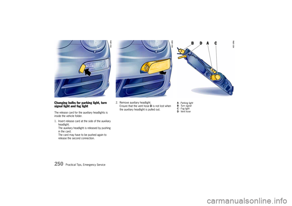
Changing bulbs for parking light, turn
signal light and fog lightThe release card for the auxiliary headlights is
inside the vehicle folder.
1. Insert release card at the side of the auxiliary
headlight.
The auxiliary headlight is released by pushing
in the card.
The card may have to be pushed again to
release the second connection.2. Remove auxiliary headlight.
Ensure that the vent hose D is not lost when
the auxiliary headlight is pulled out.
A - Parking light
B - Turn signal
C - Fog light
D - Vent hose