display Ram 1500 2015 Owner's Manual
[x] Cancel search | Manufacturer: RAM, Model Year: 2015, Model line: 1500, Model: Ram 1500 2015Pages: 871, PDF Size: 24.83 MB
Page 631 of 871

•Seasonal temperature changes will affect tire pressure,
and the TPMS will monitor the actual tire pressure in
the tire.
Premium System
The Tire Pressure Monitor System (TPMS) uses wireless
technology with wheel rim mounted electronic sensors to
monitor tire pressure levels. Sensors mounted to each
wheel as part of the valve stem transmit tire pressure
readings to the receiver module.
NOTE:It is particularly important for you to check the
tire pressure in all of the tires on your vehicle monthly
and to maintain the proper pressure.
The TPMS consists of the following components:
•Receiver module
•Four TPM sensors
•Various TPMS messages, which display in the Elec-
tronic Vehicle Information Center (EVIC)/Driver In-
formation Display (DID)
•TPM Telltale Light
The matching full size spare wheel and tire assembly (if
equipped) has a TPM sensor. The full size spare can be
used in place of any of the four road tires. A spare with a
pressure below the low-pressure limit will not cause the
“Tire Pressure Monitoring Telltale Light” to illuminate or
the chime to sound while it is stored in the spare tire
location.
Tire Pressure Monitoring Low Pressure Warnings
The “Tire Pressure Monitoring Telltale Light” will
illuminate in the instrument cluster and a chime
will sound when tire pressure is low in one or more of the
four active road tires. In addition, the EVIC/DID will
display a “LOW TIRE” message and a graphic showing
5
STARTING AND OPERATING 629
Page 632 of 871
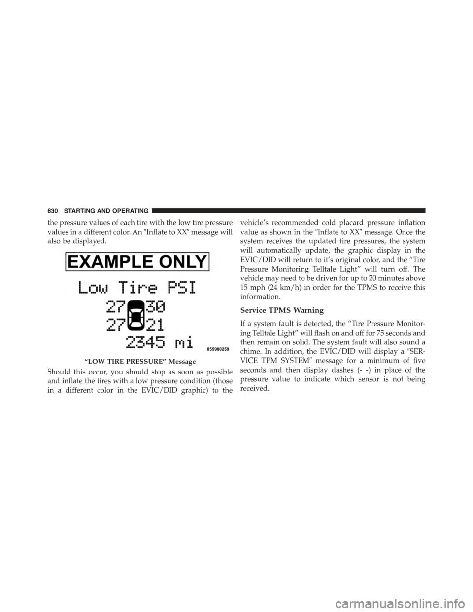
the pressure values of each tire with the low tire pressure
values in a different color. An#Inflate to XX#message will
also be displayed.
Should this occur, you should stop as soon as possible
and inflate the tires with a low pressure condition (those
in a different color in the EVIC/DID graphic) to the
vehicle’s recommended cold placard pressure inflation
value as shown in the#Inflate to XX#message. Once the
system receives the updated tire pressures, the system
will automatically update, the graphic display in the
EVIC/DID will return to it’s original color, and the “Tire
Pressure Monitoring Telltale Light” will turn off. The
vehicle may need to be driven for up to 20 minutes above
15 mph (24 km/h) in order for the TPMS to receive this
information.
Service TPMS Warning
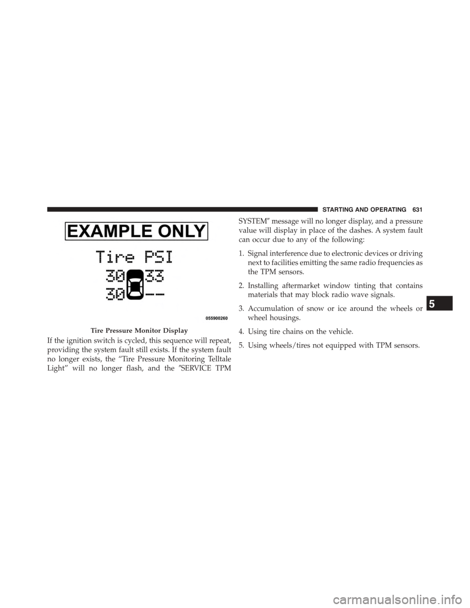
If a system fault is detected, the “Tire Pressure Monitor-
ing Telltale Light” will flash on and off for 75 seconds and
then remain on solid. The system fault will also sound a
chime. In addition, the EVIC/DID will display a#SER-
VICE TPM SYSTEM#message for a minimum of five
seconds and then display dashes (- -) in place of the
pressure value to indicate which sensor is not being
received.
“LOW TIRE PRESSURE” Message
630 STARTING AND OPERATING
Page 633 of 871
If the ignition switch is cycled, this sequence will repeat,
providing the system fault still exists. If the system fault
no longer exists, the “Tire Pressure Monitoring Telltale
Light” will no longer flash, and the#SERVICE TPM
SYSTEM#message will no longer display, and a pressure
value will display in place of the dashes. A system fault
can occur due to any of the following:
1. Signal interference due to electronic devices or driving
next to facilities emitting the same radio frequencies as
the TPM sensors.
2. Installing aftermarket window tinting that contains
materials that may block radio wave signals.
3. Accumulation of snow or ice around the wheels or
wheel housings.
4. Using tire chains on the vehicle.
5. Using wheels/tires not equipped with TPM sensors.
Tire Pressure Monitor Display
5
STARTING AND OPERATING 631
Page 634 of 871

Vehicles With Full Size Spare
1. The matching full size spare wheel and tire assembly
has a TPM sensor that can be monitored by the TPMS.
2. If you install the full size spare in place of a road tire
that has a pressure below the low-pressure warning
limit, upon the next ignition switch cycle, a chime will
sound and the “Tire Pressure Monitoring Telltale
Light” will turn ON. In addition, the EVIC/DID will
display a “LOW TIRE” message and a graphic show-
ing the low tire pressure value in a different color. An
#Inflate to XX#message will also be displayed.
3. After driving the vehicle for up to 20 minutes above
15 mph (25 km/h) the “Tire Pressure Monitoring
Telltale Light” will turn OFF and the pressure value
will be updated and return to it’s original color, as
long as no tire pressure is below the low-pressure
warning limit in any of the four active road tires.
Tire Pressure Information System (TPIS) 3500
Series Trucks
Your vehicle may be equipped with a Tire Pressure
Information System (TPIS).
The Tire Pressure Information System (TPIS) uses wire-
less technology with wheel rim mounted electronic sen-
sors to transmit tire pressure levels. Sensors mounted to
each wheel as part of the valve stem transmit tire
pressure readings to the receiver module.
NOTE:It is particularly important for you to check the
tire pressure in all of the tires on your vehicle monthly
and to maintain the proper pressure.
The TPIS consists of the following components:
•Receiver module
•Four TPM sensors (Single Rear Wheel (SRW) applica-
tions)
632 STARTING AND OPERATING
Page 635 of 871
•Six TPM sensors (Dual Rear Wheel (DRW) applica-
tions)
•Pressure display in the Electronic Vehicle Information
Center (EVIC)/Driver Information Display (DID)
The TPIS system will display all four (Single Rear Wheel
(SRW) applications) or six (Dual Rear Wheel (DRW)
applications) tire pressure values in the EVIC/DID dis-
play.
If a system fault is detected, the EVIC/DID will display a
#SERVICE TPM SYSTEM#message for a minimum of five
seconds and then display dashes (- -) in place of the
pressure value to indicate which sensor is not being
received.
If the ignition switch is cycled, this sequence will repeat,
providing the system fault still exists. If the system fault
no longer exists, the#SERVICE TPM SYSTEM#message
will no longer be displayed, and a pressure value will
display in place of the dashes. A system fault can occur
due to any of the following:
•Signal interference due to electronic devices or driving
next to facilities emitting the same radio frequencies as
the TPM sensors.
•Installing aftermarket window tinting that contains
materials that may block radio wave signals.
•Accumulation of snow or ice around the wheels or
wheel housings.
•Using tire chains on the vehicle.
•Using wheels/tires not equipped with TPM sensors.
5
STARTING AND OPERATING 633
Page 647 of 871
WARNING!
Static electricity can cause an ignition of flammable
liquid, vapor or gas in any vehicle or trailer. To
reduce risk of serious injury or death when filling
containers:
•Always place container on the ground before fill-
ing.
•Keep the pump nozzle in contact with the container
when you are filling it.
•Use only approved containers for flammable liq-
uid.
•Do not leave container unattended while filling.
•A static electric charge could cause a spark and fire
hazard.
Loose Fuel Filler Cap Message
If the vehicle diagnostic system determines
that the fuel filler cap is loose, improperly
installed, or damaged, a loose gascap indicator
will display in the EVIC/DID telltale display
area. Refer to “Electronic Vehicle Information Center
(EVIC)/Driver Information Display (DID) in “Under-
standing Your Instrument Panel” for further information.
Tighten the fuel filler cap properly and press the SELECT
button to turn off the message. If the problem continues,
the message will appear the next time the vehicle is
started.
5
STARTING AND OPERATING 645
Page 665 of 871

sliding the manual brake control lever will display the
GAIN setting for 10 seconds and the “Trailer Brake Status
Indicator Light” will not be displayed.
If a fault is detected in the trailer wiring or the Integrated
Trailer Brake Module (ITBM), the “Trailer Brake Status
Indicator Light” will flash.
GAIN Adjustment Buttons (+/-)
Pressing these buttons will adjust the brake control
power output to the trailer brakes in 0.5 increments. The
GAIN setting can be increased to a maximum of 10 or
decreased to a minimum of 0 (no trailer braking).
GAIN
The GAIN setting is used to set the trailer brake control
for the specific towing condition and should be changed
as towing conditions change. Changes to towing condi-
tions include trailer load, vehicle load, road conditions
and weather.
Adjusting GAIN
NOTE:This should only be performed in a traffic free
environment at speeds of approximately 20–25 mph
(30–40 km/h).
1. Make sure the trailer brakes are in good working
condition, functioning normally and properly ad-
justed. See your trailer dealer if necessary.
2.Hook up the trailer and make the electrical connections
according to the trailer manufacturer’s instructions.
3. When a trailer with electric/EOH brakes is plugged
in, the trailer connected message should appear in the
EVIC/DID (if the connection is not recognized by the
ITBM, braking functions will not be available), the
GAIN setting will illuminate and the correct type of
trailer must be selected from the EVIC/DID options.
4. Press the UP or DOWN button on the steering wheel
until “TRAILER TOW” appears on the screen.
5
STARTING AND OPERATING 663
Page 667 of 871
Display Messages
The trailer brake control interacts with the Electronic
Vehicle Information Center (EVIC) or Driver Information
Display (DID). Display messages, along with a single
chime, will be displayed when a malfunction is deter-
mined in the trailer connection, trailer brake control, or
on the trailer. Refer to “Electronic Vehicle Information
Center” or “Driver Information Display” in “Under-
standing Your Instrument Panel” for further information.
CAUTION!
Connecting a trailer that is not compatible with the
ITBM system may result in reduced or complete loss
of trailer braking. There may be a increase in stop-
ping distance or trailer instability which could result
in damage to your vehicle, trailer, or other property.
WARNING!
Connecting a trailer that is not compatible with the
ITBM system may result in reduced or complete loss
of trailer braking. There may be a increase in stop-
ping distance or trailer instability which could result
in personal injury.
NOTE:
•An aftermarket controller may be available for use
with trailers with air or electric-over-hydraulic trailer
brake systems. To determine the type of brakes on
your trailer and the availability of controllers, check
with your trailer manufacturer or dealer.
•Removal of the ITBM will cause errors and it may
cause damage to the electrical system and electronic
modules of the vehicle. See your authorized dealer if
an aftermarket module is to be installed.
5
STARTING AND OPERATING 665
Page 691 of 871
WARNING!(Continued)
•Being under a jacked-up vehicle is dangerous. The
vehicle could slip off the jack and fall on you. You
could be crushed. Never put any part of your body
under a vehicle that is on a jack. If you need to get
under a raised vehicle, take it to a service center
where it can be raised on a lift.
•Never start or run the engine while the vehicle is
on a jack.
•The jack is designed to be used as a tool for
changing tires only. The jack should not be used to
lift the vehicle for service purposes. The vehicle
should be jacked on a firm level surface only.
Avoid ice or slippery areas.
NOTE:If your vehicle is equipped with an air suspen-
sion system, there is a feature which allows the automatic
leveling to be disabled to assist with changing a tire.
If your vehicle is equipped with a touchscreen, this
feature can be activated through the Uconnect® system.
Refer to “Uconnect® Settings” in “Understanding Your
Instrument Panel” for further information.
If your vehicle is not equipped with a touchscreen, this
feature can be activated through the Electronic Vehicle
Information Center (EVIC) or Driver Information Display
(DID). Refer to “Electronic Vehicle Information Center
(EVIC)” or “Driver Information Display (DID)” in “Un-
derstanding Your Instrument Panel” for further informa-
tion.
Jack Location
The jack and jack tools are stored under the front
passenger seat.
Removal Of Jack And Tools (1500 Series)
To access the jack and jack tools you must remove the
plastic access cover, located on the side of the front
6
WHAT TO DO IN EMERGENCIES 689
Page 753 of 871

ONBOARD DIAGNOSTIC SYSTEM (OBD II)
Your vehicle is equipped with a sophisticated onboard
diagnostic system called OBD II. This system monitors
the performance of the emissions, engine, and automatic
transmission control systems. When these systems are
operating properly, your vehicle will provide excellent
performance and fuel economy, as well as engine emis-
sions well within current government regulations.
If any of these systems require service, the OBD II system
will turn on the “Malfunction Indicator Light (MIL).” It
will also store diagnostic codes and other information to
assist your service technician in making repairs. Al-
though your vehicle will usually be drivable and not
need towing, see your authorized dealer for service as
soon as possible.
CAUTION!
•Prolonged driving with the MIL on could cause
further damage to the emission control system. It
could also affect fuel economy and driveability.
The vehicle must be serviced before any emissions
tests can be performed.
•If the MIL is flashing, while the engine is running,
severe catalytic converter damage and power loss
will soon occur. Immediate service is required.
Loose Fuel Filler Cap Message
If the vehicle diagnostic system determines
that the fuel filler cap is loose, improperly
installed, or damaged, a loose gascap indicator
will display in the EVIC/DID telltale display
area. Refer to “Electronic Vehicle Information Center
7
MAINTAINING YOUR VEHICLE 751