lock Ram 1500 2018 Owner's Manual
[x] Cancel search | Manufacturer: RAM, Model Year: 2018, Model line: 1500, Model: Ram 1500 2018Pages: 372, PDF Size: 7.1 MB
Page 41 of 372

IconDescription
Temperature Control
Press the arrows on the touchscreen or faceplate to regulate the temperature of the air inside the passenger compart-
ment. Pressing the down arrow indicates cooler temperatures, and pressing the up arrow indicates warmer tempera-
tures.
Blower Control
There are seven blower speeds. Press the buttons to regulate the amount of air forced through the system in any mode
you select. The blower speed increases as you move the control clockwise from the off position.
Panel Mode
Panel Mode
Air comes from the outlets in the instrument panel. Each of these outlets can be individually adjusted to direct the flow
of air. The air vanes of the center outlets and outboard outlets can be moved up and down or side to side to regulate
airflow direction. There is a shut off wheel located below the air vanes to shut off or adjust the amount of airflow from
these outlets.
Bi-Level Mode
Bi-Level Mode
Air comes from the instrument panel outlets and floor outlets. A slight amount of air is directed through the defrost and
side window demister outlets.
NOTE:
Bi-Level mode is designed under comfort conditions to provide cooler air out of the panel outlets and warmer air from
the floor outlets.
Floor Mode
Floor Mode
Air comes from the floor outlets. A slight amount of air is directed through the defrost and side window demister out-
lets.
39
Page 47 of 372

IconDescription
SYNC Button — If Equipped
Press the SYNC button on the touchscreen to toggle the SYNC feature on/off. The SYNC indicator is illuminated when
this feature is enabled. SYNC is used to synchronize the passenger temperature setting with the driver temperature set-
ting. The SYNC feature also synchronizes the rear passengers’ temperature to the driver temperature setting. Changing
the passenger temperature setting while in SYNC will automatically exit this feature.
Faceplate Knob
Touchscreen Buttons
Blower Control
Blower Control is used to regulate the amount of air forced through the climate system. There are seven blower speeds
available. The speeds can be selected using either the blower control knob on the faceplate or the buttons on the touch-
screen.
• Faceplate: The blower speed increases as you turn the blower control knob clockwise from the lowest blower setting. The
blower speed decreases as you turn the blower control knob counterclockwise.
• Touchscreen:
Use the small blower icon to reduce the blower setting and the large blower icon to increase the blower
setting. Blower can also be selected by pressing the blower bar area between the icons. For Uconnect 3, press the button
to access the blower screen and control the blower.
Panel Mode
Panel Mode
Air comes from the outlets in the instrument panel. Each of these outlets can be individually adjusted to direct the flow
of air. The air vanes of the center outlets and outboard outlets can be moved up and down or side to side to regulate
airflow direction. There is a shut off wheel located below the air vanes to shut off or adjust the amount of airflow from
these outlets.
Bi-Level Mode
Bi-Level Mode
Air comes from the instrument panel outlets and floor outlets. A slight amount of air is directed through the defrost and
side window demister outlets.
NOTE:
Bi-Level mode is designed under comfort conditions to provide cooler air out of the panel outlets and warmer air from
the floor outlets.
45
Page 51 of 372
POWER SUNROOF — IF EQUIPPED
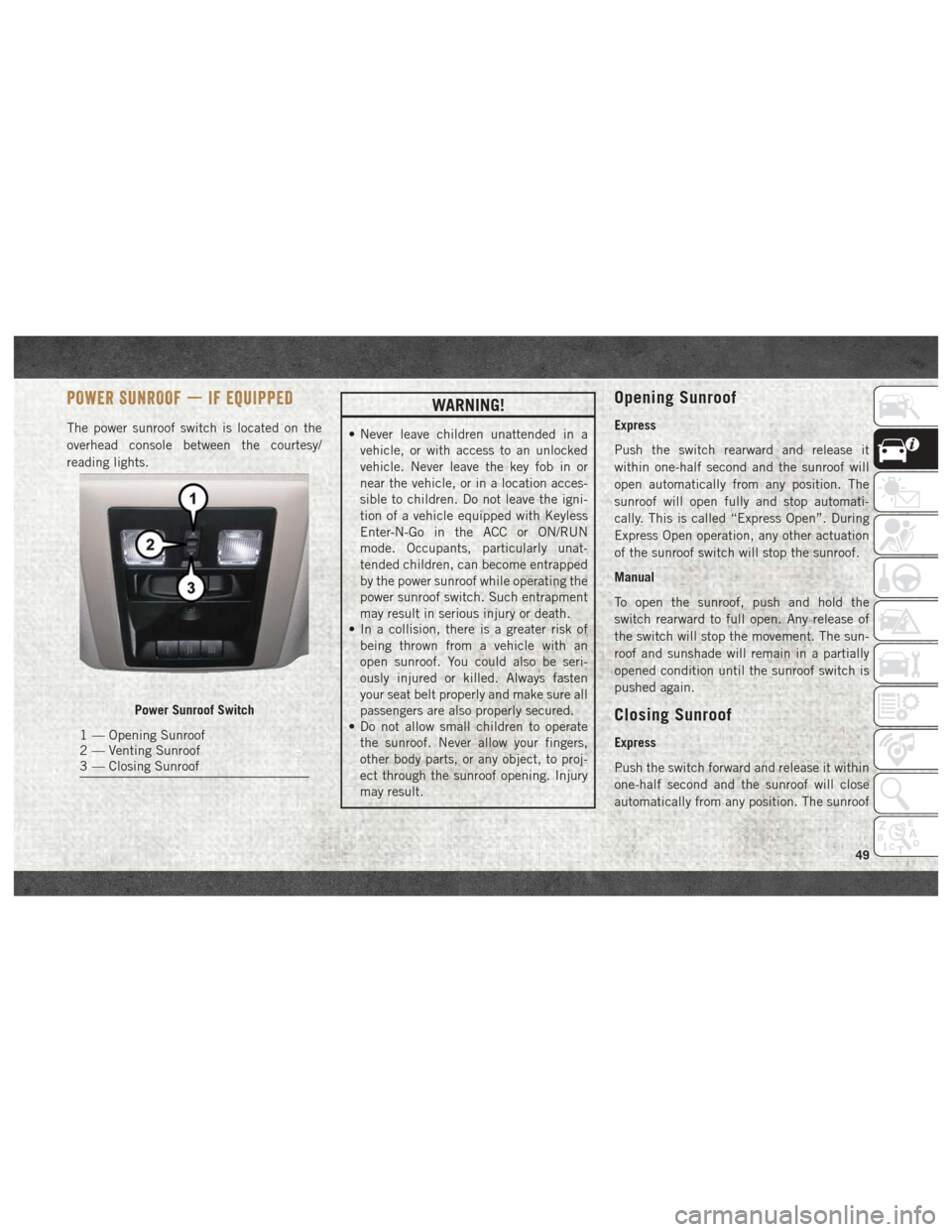
The power sunroof switch is located on the
overhead console between the courtesy/
reading lights.
WARNING!
• Never leave children unattended in avehicle, or with access to an unlocked
vehicle. Never leave the key fob in or
near the vehicle, or in a location acces-
sible to children. Do not leave the igni-
tion of a vehicle equipped with Keyless
Enter-N-Go in the ACC or ON/RUN
mode. Occupants, particularly unat-
tended children, can become entrapped
by the power sunroof while operating the
power sunroof switch. Such entrapment
may result in serious injury or death.
• In a collision, there is a greater risk of
being thrown from a vehicle with an
open sunroof. You could also be seri-
ously injured or killed. Always fasten
your seat belt properly and make sure all
passengers are also properly secured.
• Do not allow small children to operate
the sunroof. Never allow your fingers,
other body parts, or any object, to proj-
ect through the sunroof opening. Injury
may result.
Opening Sunroof
Express
Push the switch rearward and release it
within one-half second and the sunroof will
open automatically from any position. The
sunroof will open fully and stop automati-
cally. This is called “Express Open”. During
Express Open operation, any other actuation
of the sunroof switch will stop the sunroof.
Manual
To open the sunroof, push and hold the
switch rearward to full open. Any release of
the switch will stop the movement. The sun-
roof and sunshade will remain in a partially
opened condition until the sunroof switch is
pushed again.
Closing Sunroof
Express
Push the switch forward and release it within
one-half second and the sunroof will close
automatically from any position. The sunroof
Power Sunroof Switch
1 — Opening Sunroof
2 — Venting Sunroof
3 — Closing Sunroof
49
Page 53 of 372
2. Reach into the opening beneath the cen-ter of the hood and push the safety latch
lever to the left to release it, before raising
the hood.
To Close The Hood
Lower the hood to approximately 12 inches
(30 cm) from the engine compartment and
drop it. Make sure that the hood is completely
closed.
WARNING!
Be sure the hood is fully latched before
driving your vehicle. If the hood is not fully
latched, it could open when the vehicle is
in motion and block your vision. Failure to
follow this warning could result in serious
injury or death.
CAUTION!
To prevent possible damage, do not slam
the hood to close it. Use a firm downward
push at the front center of the hood to
ensure that both latches engage.
UNIVERSAL GARAGE DOOR OPENER
(HOMELINK)
• HomeLink replaces up to three hand-heldtransmitters that operate devices such as
garage door openers, motorized gates,
lighting or home security systems. The
HomeLink unit is powered by your vehicles
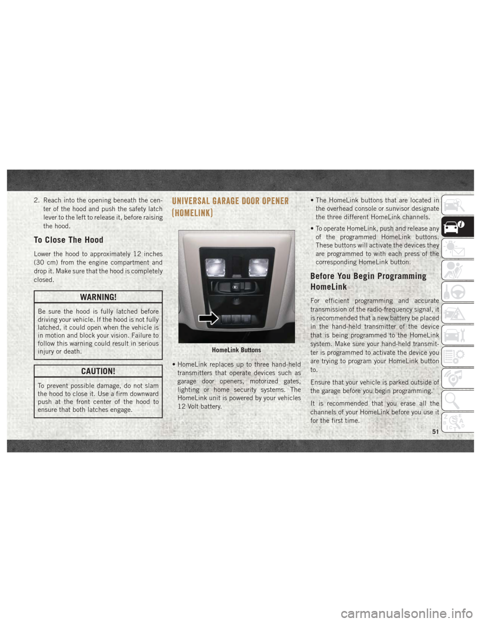
12 Volt battery. • The HomeLink buttons that are located in
the overhead console or sunvisor designate
the three different HomeLink channels.
• To operate HomeLink, push and release any of the programmed HomeLink buttons.
These buttons will activate the devices they
are programmed to with each press of the
corresponding HomeLink button.
Before You Begin Programming
HomeLink
For efficient programming and accurate
transmission of the radio-frequency signal, it
is recommended that a new battery be placed
in the hand-held transmitter of the device
that is being programmed to the HomeLink
system. Make sure your hand-held transmit-
ter is programmed to activate the device you
are trying to program your HomeLink button
to.
Ensure that your vehicle is parked outside of
the garage before you begin programming.
It is recommended that you erase all the
channels of your HomeLink before you use it
for the first time.
HomeLink Buttons
51
Page 61 of 372

NOTE:
Once initiated by the "Cargo Camera" button,
the Cargo Camera image may be deactivated
by pressing the "X" soft button. On deactiva-
tion, the previous selected screen will appear.
RAMBOX — IF EQUIPPED
The RamBox system is an integrated pickup
box storage and cargo management system
consisting of three features:
• Integrated box side storage bins• Cargo extender/divider
• Bed rail tie-down system
RamBox Integrated Box Side
Storage Bins
Cargo storage bins are located on both sides
of the pickup box. The cargo storage bins
provide watertight, lockable, illuminated
storage for up to 150 lbs (68 kg) for 1500 se-
ries vehicles or 300 lbs (136 kg) for
2500 and 3500 series vehicles of evenly
distributed cargo.
CAUTION!
Failure to follow the following items could
cause damage to the vehicle:
• Assure that all cargo inside the storage
bins is properly secured.
• Do not exceed cargo weight rating of
150 lb (68 kg) 1500 series vehicles or
300 lbs (136 kg) for 2500 and 3500 se-
ries vehicles per bin.
To open a storage bin with the RamBox un-
locked, push and release the button located
on the lid. The RamBox lid will open upward
to allow hand access. Lift the lid to fully
open.
NOTE:
RamBox will not open when the pushbutton
is pushed if the RamBox is locked.
Cargo Camera Display
RamBox Features
1 — Bed Extender
2 — Bed Rail Tie-Down System Adjust-
able Cleats
3 — Storage Bin
4 — Push The Button To Open
59
Page 62 of 372
CAUTION!
Leaving the lid open for extended periods
of time could cause the vehicle battery to
discharge. If the lid is required to stay
open for extended periods of time, it is
recommended that the bin lights be
turned off manually using the on/off
switch.
The interior of the RamBox will automatically
illuminate when the lid is opened. In addition
to the automatic illumination switch, there is
a manual on/off switch located at the rear of
each storage bin. Pushing the switch once
will turn off the bin lights, pushing the switch
again will turn the lights back on.
Cargo bins feature two removable drain plugs
(to allow water to drain from bins). To remove
plug, pull up on the edge. To install push plug
downward into drain hole.
NOTE:
Provisions are provided in the bins for cargo
dividers and shelf supports. These accesso-
ries (in addition to other RamBox accesso-
ries) are available from Mopar.
Locking And Unlocking RamBox
Push and release the lock or unlock button on
the key fob to lock and unlock all doors, the
tailgate and the RamBox (if equipped). Refer
to “Keys” in “Getting To Know Your Vehicle”
in the Owner’s Manual for further details. The
RamBox storage bins can be locked using the
vehicle key. To lock and unlock the storage
bin, insert the key into the keyhole on the
push button and turn clockwise to lock or
counterclockwise to unlock. Always return
the key to the upright (vertical) position be-
fore removing the key from the push button.
CAUTION!
• Ensure cargo bin lids are closed and latched before moving or driving vehicle.
• Loads applied to the top of the bin lid
should be minimized to prevent damage
to the lid and latching/hinging mecha-
nisms.
• Damage to the RamBox bin may occur
due to heavy/sharp objects placed in bin
that shift due to vehicle motion. In order
to minimize potential for damage, se-
CAUTION!
cure all cargo to prevent movement and
protect inside surfaces of bin from
heavy/sharp objects with appropriate
padding.
RamBox Safety Warning
Carefully follow these warnings to help pre-
vent personal injury or damage to your
vehicle:
WARNING!
• Always close the storage bin coverswhen your vehicle is unattended.
• Do not allow children to have access to
the storage bins. Once in the storage
bin, young children may not be able to
escape. If trapped in the storage bin,
children can die from suffocation or heat
stroke.
• In an accident, serious injury could re-
sult if the storage bin covers are not
properly latched.
GETTING TO KNOW YOUR VEHICLE
60
Page 63 of 372

WARNING!
• Do not drive the vehicle with the storagebin covers open.
• Keep the storage bin covers closed and
latched while the vehicle is in motion.
• Do not use a storage bin latch as a tie
down.
RamBox Storage Bin Cover Emergency Re-
lease Lever — If Equipped
As a security measure, a Storage Bin Cover
Emergency Release is built into the storage
bin cover latching mechanism.
NOTE:
In the event of an individual being locked
inside the storage bin, the storage bin cover
can be opened from inside of the bin by
pulling on the glow-in-the-dark lever at-
tached to the storage bin cover latching
mechanism.
Bed Extender — If Equipped
The bed extender has three functional posi-
tions:
• Storage Position • Divider Position
• Extender Position
Storage Position
The storage position for the bed extender is at
the front of the truck bed which maximizes
the bed cargo area when not in use.
To install the bed extender into the storage
position, perform the following:
1. Make sure the center handle is unlocked
using the vehicle key and rotate the center
handle vertically to release the extender
side gates.
2. With the side gates open, position the extender fully forward in the bed against
the front panel.
3. Rotate the side gates closed allowing the outboard ends to be positioned in front of
the cargo tie down loops.
4. Rotate the center handle horizontally to secure the side gates in the closed
position.
5. Lock the center handle using the vehicle key to secure the panel into place.
Divider Position
The divider position is intended for managing
your cargo and assisting in keeping cargo
from moving around the bed. There are 11 di-
vider slots along the bed inner panels which
allow for various positions to assist in manag-
ing your cargo.
To install the bed extender into a divider
position, perform the following:
1. Make sure the center handle is unlocked
using the vehicle key and rotate the center
handle vertically to release the extender
side gates.
2. With the side gates open, position the extender so the outboard ends align with
the intended slots in the sides of the bed.
3. Rotate the side gates closed so that the outboard ends are secured into the in-
tended slots of the bed.
4. Rotate the center handle horizontally to secure the side gates in the closed
position.
5. Lock the center handle to secure the panel into place.
61
Page 64 of 372

Extender Position
The extender position allows you to load the
bed of the truck beyond the tail gate. The bed
extender will add an additional 15 inches
(38 cm) in the back of the truck when addi-
tional cargo room is needed. The extender
position utilizes a locating pin and rotating
handle located on both sides of the truck bed
near the tailgate.
To install the bed extender into the extender
position, perform the following:
1. Lower the tailgate.
2. Make sure the center handle is unlockedand rotate the center handle vertically in
order to release the extender side gates.
3. Fit the end of the side gate ends onto the pin and handle.
4. Rotate the handles to the horizontal posi- tion to secure into place.WARNING!
To reduce the risk of potential injury or
property damage:
• Cargo must be secured.
• Do not exceed cargo load rating of yourvehicle.
• Secure all loads to truck utilizing cargo
tie downs.
• Extender should not be used as cargo tie
down.
• When vehicle is in motion do not exceed
150 lbs (68 kg) load on the tailgate.
• The bed extender is not intended for off
road use.
• When not in use, the extender/divider
should be in stowed or divider position
with the tailgate closed.
• When in use all handles are to be in the
locked position.
Bed Rail Tie-Down System
CAUTION!
The maximum load per cleat should not
exceed 250 lbs (113 kg) and the angle of
CAUTION!
the load on each cleat should not exceed
45 degrees above horizontal, or damage to
the cleat or cleat rail may occur.
There are two adjustable cleats on each side
of the bed that can be used to assist in
securing cargo.
Each cleat must be located and tightened
down in one of the detents, along either rail,
in order to keep cargo properly secure.
To move the cleat to any position on the rail,
turn the nut counterclockwise, approximately
three turns. Then pull out on the cleat and
slide it to the detent nearest the desired
location. Make sure the cleat is seated in the
detent and tighten the nut.
To remove the cleats from the utility rail,
remove the end cap screw located in the
center of the end cap, using a #T30 Torx
head driver. Remove the end cap and slide
the cleat off the end of the rail.
GETTING TO KNOW YOUR VEHICLE
62
Page 65 of 372
EASY-OFF TAILGATE
To simplify mounting of a camper unit with an
overhang, the tailgate can be removed.
NOTE:
If your vehicle is equipped with a rear camera
or Remote Keyless Entry, the electrical con-
nector must be disconnected prior to remov-
ing the tailgate.
Removing The Tailgate
1. Disconnect the wiring harness for the rearcamera or Remote Keyless Entry (if
equipped).
2. Unlatch the tailgate and remove the sup- port cables by releasing the lock tang from
the pivot. 3. Raise the right side of the tailgate until
the right side pivot clears the hanger
bracket.
4. Slide the entire tailgate to the right to free the left side pivot.
5. Remove the tailgate from the vehicle.
NOTE:
Do not carry the tailgate loose in the truck
pickup box.Locking Tailgate
The lock is located next to the tailgate
handle. The tailgate can be locked using the
vehicle key or by locking the truck with the
key fob if equipped with remote keyless entry.
TRI-FOLD TONNEAU COVER
The Tonneau Cover can be removed and rein-
stalled by using the locking clamps located
underneath the Tonneau Cover. Refer to the
Owner’s Manual for further information.
NOTE:
Be sure that the Tonneau Cover is secured
before driving.
63
Page 77 of 372
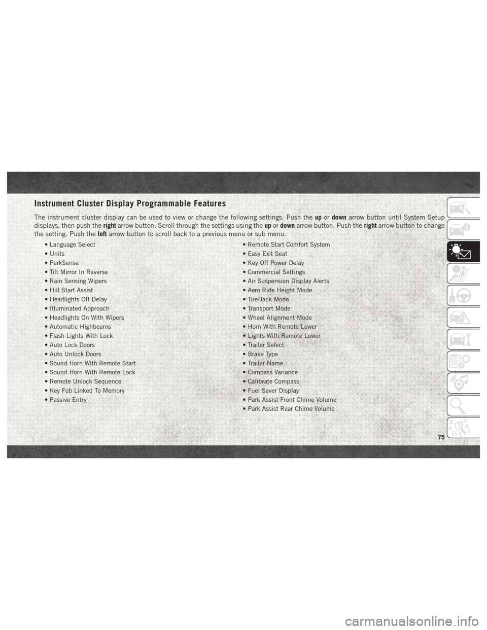
Instrument Cluster Display Programmable Features
The instrument cluster display can be used to view or change the following settings. Push theupordown arrow button until System Setup
displays, then push the rightarrow button. Scroll through the settings using the upordown arrow button. Push the rightarrow button to change
the setting. Push the leftarrow button to scroll back to a previous menu or sub menu.
• Language Select • Remote Start Comfort System
• Units • Easy Exit Seat
• ParkSense • Key Off Power Delay
• Tilt Mirror In Reverse • Commercial Settings
• Rain Sensing Wipers • Air Suspension Display Alerts
• Hill Start Assist • Aero Ride Height Mode
• Headlights Off Delay • Tire/Jack Mode
• Illuminated Approach • Transport Mode
• Headlights On With Wipers • Wheel Alignment Mode
• Automatic Highbeams • Horn With Remote Lower
• Flash Lights With Lock • Lights With Remote Lower
• Auto Lock Doors • Trailer Select
• Auto Unlock Doors • Brake Type
• Sound Horn With Remote Start • Trailer Name
• Sound Horn With Remote Lock • Compass Variance
• Remote Unlock Sequence • Calibrate Compass
• Key Fob Linked To Memory • Fuel Saver Display
• Passive Entry • Park Assist Front Chime Volume
• Park Assist Rear Chime Volume
75