light Ram 1500 2018 Manual PDF
[x] Cancel search | Manufacturer: RAM, Model Year: 2018, Model line: 1500, Model: Ram 1500 2018Pages: 372, PDF Size: 7.1 MB
Page 207 of 372
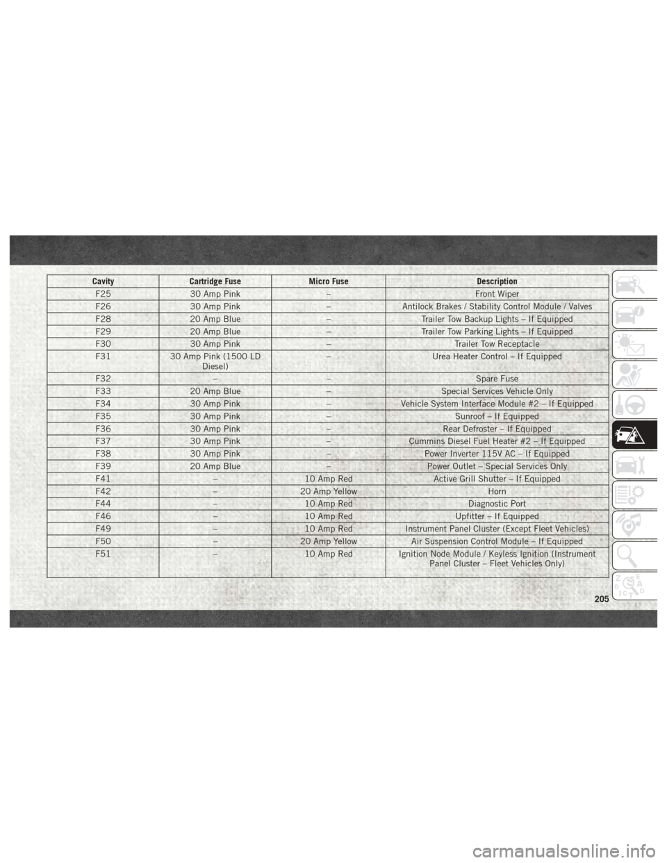
CavityCartridge Fuse Micro Fuse Description
F25 30 Amp Pink – Front Wiper
F26 30 Amp Pink –Antilock Brakes / Stability Control Module / Valves
F28 20 Amp Blue –Trailer Tow Backup Lights – If Equipped
F29 20 Amp Blue –Trailer Tow Parking Lights – If Equipped
F30 30 Amp Pink –Trailer Tow Receptacle
F31 30 Amp Pink (1500 LD
Diesel) –
Urea Heater Control – If Equipped
F32 –– Spare Fuse
F33 20 Amp Blue –Special Services Vehicle Only
F34 30 Amp Pink –Vehicle System Interface Module #2 – If Equipped
F35 30 Amp Pink –Sunroof – If Equipped
F36 30 Amp Pink –Rear Defroster – If Equipped
F37 30 Amp Pink –Cummins Diesel Fuel Heater #2 – If Equipped
F38 30 Amp Pink –Power Inverter 115V AC – If Equipped
F39 20 Amp Blue –Power Outlet – Special Services Only
F41 –10 Amp Red Active Grill Shutter – If Equipped
F42 –20 Amp Yellow Horn
F44 –10 Amp Red Diagnostic Port
F46 –10 Amp Red Upfitter – If Equipped
F49 –10 Amp Red Instrument Panel Cluster (Except Fleet Vehicles)
F50 –20 Amp Yellow Air Suspension Control Module – If Equipped
F51 –10 Amp Red Ignition Node Module / Keyless Ignition (Instrument
Panel Cluster – Fleet Vehicles Only)
205
Page 208 of 372

CavityCartridge Fuse Micro Fuse Description
F52 –5 Amp Tan Battery Sensor
F53 –20 Amp Yellow Trailer Tow – Left Turn/Stop Lights
F54 –20 Amp Yellow Adjustable Pedals
F56 –15 Amp Blue Additional Diesel Content – If Equipped
F57 –20 Amp Yellow Transmission
F58 –20 Amp Yellow Spare Fuse
F59 –10 Amp Red SCR Relay – If Equipped
F60 –15 Amp Blue Underhood Lamp
F61 –10 Amp Red (1500 LD Die-
sel & Cummins Diesel) PM Sensor – If Equipped
F62 –10 Amp Red Air Conditioning Clutch
F63 –20 Amp Yellow Ignition Coils (Gas), Urea Heater (Cummins Diesel)
F64 –25 Amp Clear Fuel Injectors / Powertrain
F65 –– Spare Fuse
F66 –10 Amp Red Sunroof / Passenger Window Switches / Rain Sensor
F67 –10 Amp Red CD / DVD / Bluetooth Hands-free Module – If Equipped
F69 –15 Amp Blue Mod SCR 12V (Cummins Diesel) – If Equipped
F70 –30 Amp Green Fuel Pump Motor
F71 –25 Amp Clear Amplifier
F72 –10 Amp Red PCM – If Equipped
F73 –20 Amp Yellow Fuel Transfer Pump (HD Only) – If Equipped
F74 –20 Amp Yellow (Gas Engine
& 1500 LD Diesel) Brake Vacuum Pump Gas/Diesel – If Equipped
IN CASE OF EMERGENCY
206
Page 209 of 372

CavityCartridge Fuse Micro Fuse Description
F75 –10 Amp Red Coolant Temperature Valve Actuator
F76 –10 Amp Red Antilock Brakes / Electronic Stability Control
F77 –10 Amp Red Drivetrain Control Module/Front Axle Disconnect Module
F78 –10 Amp Red Engine Control Module / Electric Power Steering
F79 –15 Amp Blue Clearance Lights
F80 –10 Amp Red Universal Garage Door Opener / Compass
F81 –20 Amp Yellow Trailer Tow Right Turn / Stop Lights
F82 –10 Amp Red Steering Column Control Module / Cruise Control
F84 –15 Amp Blue Switch Bank / Instrument Cluster
F85 –10 Amp Red Airbag Module
F86 –10 Amp Red Airbag Module
F87 –10 Amp Red Air Suspension – If Equipped / Trailer Tow / Steering Col-
umn Control Module
F88 –15 Amp Blue Instrument Panel Cluster
F90/F91 –20 Amp Yellow Power Outlet (Rear Seats) Customer Selectable
F93 –20 Amp Yellow Cigar Lighter
F94 –10 Amp Red Shifter / Transfer Case Module
F95 –10 Amp Red Rear Camera / Park Assist
F96 –10 Amp Red Rear Seat Heater Switch
F97 –25 Amp Clear Rear Heated Seats & Heated Steering Wheel – If
Equipped
F98 –25 Amp Clear Front Heated Seats – If Equipped
F99 –10 Amp Red Climate Control
207
Page 215 of 372
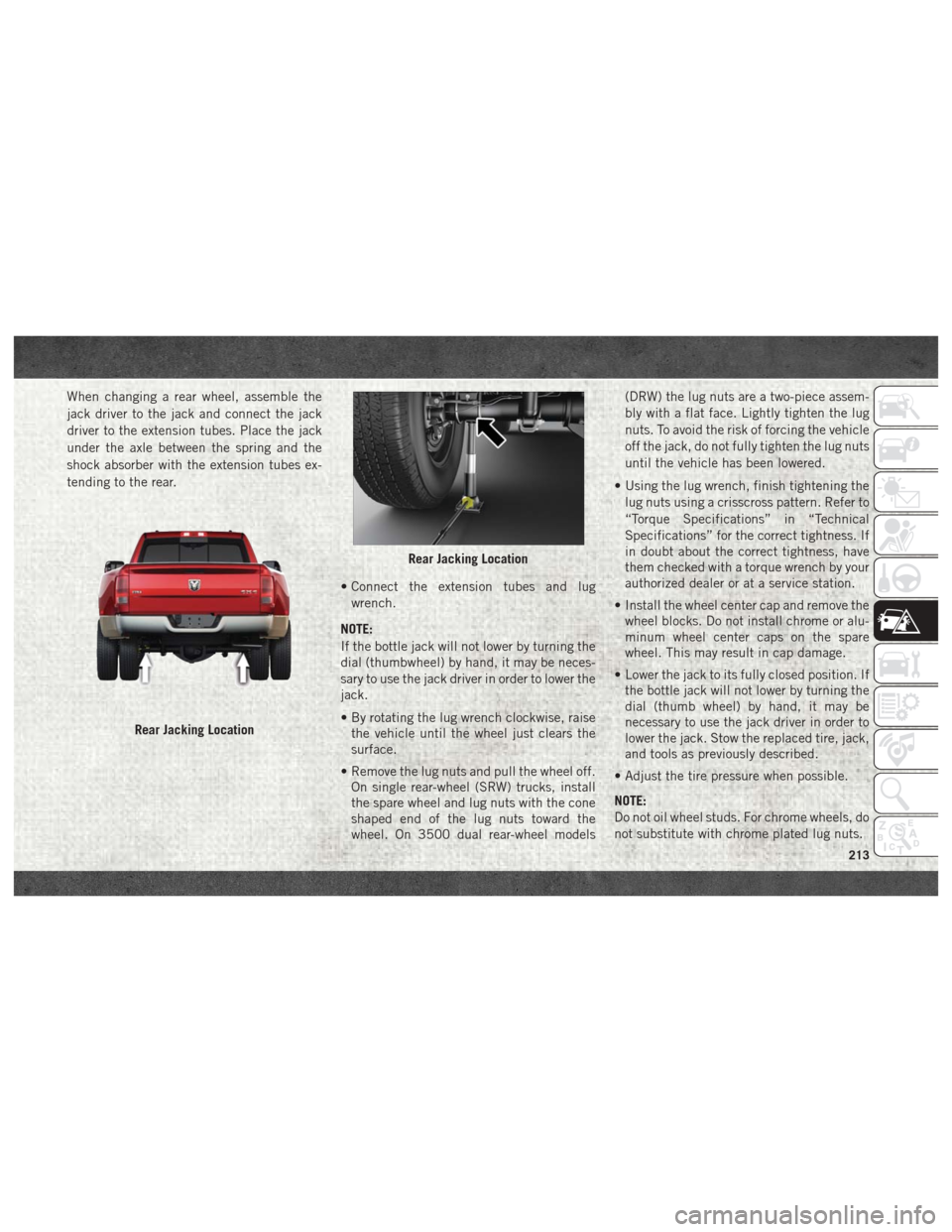
When changing a rear wheel, assemble the
jack driver to the jack and connect the jack
driver to the extension tubes. Place the jack
under the axle between the spring and the
shock absorber with the extension tubes ex-
tending to the rear.• Connect the extension tubes and lugwrench.
NOTE:
If the bottle jack will not lower by turning the
dial (thumbwheel) by hand, it may be neces-
sary to use the jack driver in order to lower the
jack.
• By rotating the lug wrench clockwise, raise the vehicle until the wheel just clears the
surface.
• Remove the lug nuts and pull the wheel off. On single rear-wheel (SRW) trucks, install
the spare wheel and lug nuts with the cone
shaped end of the lug nuts toward the
wheel. On 3500 dual rear-wheel models (DRW) the lug nuts are a two-piece assem-
bly with a flat face. Lightly tighten the lug
nuts. To avoid the risk of forcing the vehicle
off the jack, do not fully tighten the lug nuts
until the vehicle has been lowered.
• Using the lug wrench, finish tightening the lug nuts using a crisscross pattern. Refer to
“Torque Specifications” in “Technical
Specifications” for the correct tightness. If
in doubt about the correct tightness, have
them checked with a torque wrench by your
authorized dealer or at a service station.
• Install the wheel center cap and remove the wheel blocks. Do not install chrome or alu-
minum wheel center caps on the spare
wheel. This may result in cap damage.
• Lower the jack to its fully closed position. If the bottle jack will not lower by turning the
dial (thumb wheel) by hand, it may be
necessary to use the jack driver in order to
lower the jack. Stow the replaced tire, jack,
and tools as previously described.
• Adjust the tire pressure when possible.
NOTE:
Do not oil wheel studs. For chrome wheels, do
not substitute with chrome plated lug nuts.
Rear Jacking Location
Rear Jacking Location
213
Page 220 of 372

the end of the lug wrench to pull the caps off.
The wheel skin can now be removed.
CAUTION!
• Use a pulling motion to remove the hubcap. Do not use a twisting motion when
removing the hub cap, damage to the
hub cap; finish may occur.
• The rear hub caps on the dual rear wheel
has two pull off notches. Make sure that
the hook of the jack handle driver is
located squarely in the cap notch before
attempting to pull off.
You must use the flat end of the lug wrench to
pull off the wheel skins. Locate the hub cap
pull notches (2 notches on each cap). Insert
the flat tip completely and using a back and
forth motion, loosen the wheel skin. Repeat
this procedure around the tire until the skin
pops off.
Replace the wheel skins first using a rubber
mallet. When replacing the hub caps, tilt the
cap retainer over the lug nut bolt circle and strike the high side down with a rubber mal-
let. Be sure that the hub caps and wheel
skins are firmly seated around the wheel.JUMP STARTING
If your vehicle has a discharged battery, it can
be jump started using a set of jumper cables
and a battery in another vehicle, or by using a
portable battery booster pack. Jump starting
can be dangerous if done improperly, so
please follow the procedures in this section
carefully.
WARNING!
Do not attempt jump starting if the battery
is frozen. It could rupture or explode and
cause personal injury.
CAUTION!
Do not use a portable battery booster pack
or any other booster source with a system
voltage greater than 12 Volts or damage to
the battery, starter motor, alternator or
electrical system may occur.NOTE:
When using a portable battery booster pack,
follow the manufacturer's operating instruc-
tions and precautions.
Preparations For Jump Start
The battery in your vehicle is located in the
front of the engine compartment, behind the
left headlight assembly.
Positive Jumping Location
IN CASE OF EMERGENCY
218
Page 232 of 372
SCHEDULED SERVICING — GASOLINE
ENGINE
Your vehicle is equipped with an automatic
oil change indicator system. The oil change
indicator system will remind you that it is
time to take your vehicle in for scheduled
maintenance.
Based on engine operation conditions, the oil
change indicator message will illuminate.
This means that service is required for your
vehicle. Operating conditions such as fre-
quent short-trips, trailer tow, extremely hot or
cold ambient temperatures, and E85 fuel
usage will influence when the “Oil Change
Required” message is displayed. Severe Op-
erating Conditions can cause the change oil
message to illuminate as early as
3,500 miles (5,600 km) since last reset.
Have your vehicle serviced as soon as pos-
sible, within the next 500 miles (805 km).Your authorized dealer will reset the oil
change indicator message after completing
the scheduled oil change. If a scheduled oil
change is performed by someone other than
your authorized dealer, the message can be
reset by referring to the steps described un-
der “Instrument Cluster Display” in “Getting
To Know Your Instrument Panel”.
1500 Models Only
NOTE:
Under no circumstances should oil change
intervals exceed 10,000 miles (16,000 km),
twelve months or 350 hours of engine run
time, whichever comes first. The 350 hours
of engine run or idle time is generally only a
concern for fleet customers.
2500 – 3500 Models Only
NOTE:
Under no circumstances should oil change
intervals exceed 8,000 miles (13,000 km),
twelve months or 350 hours of engine run
time, whichever comes first. The 350 hours
of engine run or idle time is generally only a
concern for fleet customers. Severe Duty All Models
NOTE:
Change Engine Oil at 4,000 miles
(6,500 km) or 350 hours of engine run time
if the vehicle is operated in a dusty and off
road environment or is operated predomi-
nantly at idle, or only very low engine RPM’s.
This type of vehicle use is considered Severe
Duty.
Once A Month Or Before A Long Trip:
• Check engine oil level
• Check windshield washer fluid level
• Check tire pressure and look for unusual
wear or damage. Rotate tires at the first
sign of irregular wear, even if it occurs
before the oil indicator system turns on.
• Check the fluid levels of the coolant reser- voir, brake master cylinder, power steering
(2500/3500 Models Only) and automatic
transmission (six-speed only) and fill as
needed
• Check function of all interior and exterior lights
SERVICING AND MAINTENANCE
230
Page 236 of 372
WARNING!
• You can be badly injured working on oraround a motor vehicle. Do only service
work for which you have the knowledge
and the right equipment. If you have any
doubt about your ability to perform a
service job, take your vehicle to a com-
petent mechanic.
• Failure to properly inspect and maintain
your vehicle could result in a component
malfunction and effect vehicle handling
and performance. This could cause an
accident.
Heavy Duty Use Of The Vehicle
Change engine oil at 4,000 miles (6,500 km)
or 350 hours of engine run time if the vehicle
is operated in a dusty and off road environ-
ment or is operated predominately at idle or
only very low engine RPM’s. This type of
vehicle use is considered Severe Duty.
SCHEDULED SERVICING — 1500 3.0L
DIESEL ENGINE
Your vehicle is equipped with an automatic
oil change indicator system. The oil change
indicator system will remind you that it is
time to take your vehicle in for scheduled
maintenance.
Based on engine operation conditions, the oil
change indicator message will illuminate.
This means that service is required for your
vehicle. Operating conditions such as fre-
quent short-trips, trailer tow, extremely hot or
cold ambient temperatures will influence
when the “Oil Change Required” message is
displayed. Severe Operating Conditions will
cause the change oil message to illuminate
more frequently. Have your vehicle serviced
as soon as possible, within the next
500 miles (805 km). Your authorized dealer will reset the oil
change indicator message after completing
the scheduled oil change. If a scheduled oil
change is performed by someone other than
your authorized dealer, the message can be
reset by referring to the steps described un-
der “Instrument Cluster Display” in “Getting
To Know Your Instrument Panel” in your Own-
er’s Manual for further information.
NOTE:
Under no circumstances should oil change
intervals exceed 10,000 miles (16,000 km)
or twelve months, whichever comes first.
Once A Month Or Before A Long Trip:
• Check engine oil level
• Check windshield washer fluid level
• Check the tire inflation pressures and look
for unusual wear or damage
• Check the fluid levels of the coolant reser- voir, brake master cylinder, and power
steering, and fill as needed
• Check function of all interior and exterior lights
SERVICING AND MAINTENANCE
234
Page 251 of 372

DEALER SERVICE — 3.0L DIESEL
Your authorized dealer has the qualified ser-
vice personnel, special tools, and equipment
to perform all service operations in an expert
manner. Service Manuals are available which
include detailed service information for your
vehicle. Refer to these Service Manuals be-
fore attempting any procedure yourself.
NOTE:
Intentional tampering with emissions control
systems may void your warranty and could
result in civil penalties being assessed
against you.
WARNING!
You can be badly injured working on or
around a motor vehicle. Only do service
work for which you have the knowledge
and the proper equipment. If you have any
doubt about your ability to perform a ser-
vice job, take your vehicle to a competent
mechanic.
Engine Air Cleaner Filter
WARNING!
The air induction system (air cleaner,
hoses, etc.) can provide a measure of pro-
tection in the case of engine backfire. Do
not remove the air induction system (air
cleaner, hoses, etc.) unless such removal
is necessary for repair or maintenance.
Make sure that no one is near the engine
compartment before starting the vehicle
with the air induction system (air cleaner,
hoses, etc.) removed. Failure to do so can
result in serious personal injury.
CAUTION!
All air entering the engine intake must be
filtered. The abrasive particles in unfil-
tered air will cause rapid wear to engine
components.
Refer to the “Maintenance Plan” for the
proper maintenance intervals.
CAUTION!
Many aftermarket performance air filter
elements do not adequately filter the air
entering the engine. Use of such filters can
severely damage your engine.
Draining Fuel/Water Separator
Filter
The fuel filter/water separator filter housing is
located above the rear axle next to the fuel
tank. The best access to this water drain valve
is from under the vehicle.
CAUTION!
• Do not drain the fuel/water separator filter when the engine is running.
• Diesel fuel will damage blacktop paving
surfaces. Drain the filter into an appro-
priate container.
If water is detected in the water separator
while the engine is running, or while the
ignition switch is in the ON position, the
“Water In Fuel Indicator Light” will illumi-
249
Page 252 of 372
nate and an audible chime will be heard. At
this point, you should stop the engine and
drain the water from the filter housing.
CAUTION!
If the “Water In Fuel Indicator Light” re-
mains on, DO NOT START the engine be-
fore you drain water from the fuel filter to
avoid engine damage.
If the “Water In Fuel Indicator Light” comes
on and a single chime is heard while you are
driving, or with the ignition in the ON posi-
tion, there may be a problem with your water
separator wiring or sensor. See your autho-
rized dealer for service.
Upon proper draining of the water from the
fuel filter, the “Water In Fuel Indicator Light”
will remain illuminated for approximately
10 seconds. If the water was drained while
the engine was running, the “Water In Fuel
Indicator Light” may remain on for approxi-
mately three minutes. NOTE:
Care should be taken in disposing of used
fluids from your vehicle. Used fluids, indis-
criminately discarded, can present a problem
to the environment. Contact an authorized
dealer, service station, or government agency
for advice on recycling programs and for
where used fluids and filters can be properly
disposed of in your area.
Drain the fuel/water separator filter when the
“Water In Fuel Indicator Light” is ON. Within
10 minutes of vehicle shutdown, turn the
filter drain valve (located on the bottom of the
filter housing) counterclockwise to drain fuel/
water, then turn the ignition switch to the ON
position, and allow any accumulated water to
drain. Leave the drain valve open until all
water and contaminants have been removed.
When clean fuel is visible, close the drain
valve by turning it clockwise, and turn the
ignition switch to OFF.
If more than two ounces or 60 milliliters of
fuel have been drained, follow the directions
for “Priming If The Engine Has Run Out Of
Fuel.”
Underbody Mounted Fuel Filter
Replacement
NOTE:
Using a fuel filter that does not meet the
manufacturer's filtration and water separat-
ing requirements can severely impact fuel
system life and reliability.
CAUTION!
• Diesel fuel will damage blacktop paving
surfaces. Drain the filter into an appro-
priate container.
• Do not prefill the fuel filter when install-
ing a new fuel filter. There is a possibility
debris could be introduced into the fuel
filter during this action. It is best to
install the filter dry and allow the in-tank
lift pump to prime the fuel system.
1. Turn engine off.
2. Place a drain pan under the fuel filter assembly.
3. Open the water drain valve, and let any accumulated water drain.
4. Close the water drain valve.
SERVICING AND MAINTENANCE
250
Page 255 of 372

If the vehicle experiences a sudden loss of
engine power while being driven in heavy
snow or rain, or when plowing snow, and/or
the “SERVICE AIR FILTER” message is dis-
played on the instrument cluster along with a
chime that repeats every 60 seconds, visually
inspect the air filter for snow/ice build up or
extreme water saturation. If the air filter is
not damaged, remove all snow/ice and rein-
stall air filter. If the air filter is damaged,
replace filter element.
NOTE:
The air filter housing contains a Mass Air
Flow sensor. This sensor is critical to proper
engine operation and component longevity.
Any damage or modification to this sensor
could result in major engine and/or exhaust
aftertreatment damage. We recommend you
use Mopar brand parts.
Even though your vehicle is equipped with an
Air Filter Monitor, a visual inspection of the
air cleaner filter element is recommended
every 15,000 miles (24,000km) or
12 months – whichever occurs first.Under nocircumstances should the air cleaner filter ele-
ment exceed 30,000 miles (48,000 km) or
24 months, whichever comes first.
CAUTION!
Many aftermarket performance air filter
elements do not adequately filter the air
entering the engine. Use of such filters can
severely damage your engine.
Draining Fuel/Water Separator
Filter
There are two fuel filter assemblies. One is
located on the driver's side of the engine. The
best access to this water drain valve is from
under the hood. The second one is on the
under body, located in front of the rear axle
above the drive shaft on pick-up models. The
Chassis Cab models second filter location is
on the frame behind the front axle. The best
access to this water drain valve is from under
the vehicle.
CAUTION!
• Do not drain the fuel/water separator
filter when the engine is running.
• Diesel fuel will damage blacktop paving
surfaces. Drain the filter into an appro-
priate container.
If water is detected in the water separator
while the engine is running, or while the
ignition switch is in the ON position, the
“Water In Fuel Indicator Light” will illumi-
nate and an audible chime will be heard five
times. At this point you should stop the
engine and drain the water from both of the
filters.
CAUTION!
If the “Water In Fuel Indicator Light” re-
mains on, DO NOT START the engine be-
fore you drain water from the fuel filters to
avoid engine damage.
If the “Water In Fuel Indicator Light” comes
on and a single chime is heard while you are
driving, or with the ignition switch in the ON
253