light Ram 1500 2018 Manual Online
[x] Cancel search | Manufacturer: RAM, Model Year: 2018, Model line: 1500, Model: Ram 1500 2018Pages: 372, PDF Size: 7.1 MB
Page 256 of 372
position, there may be a problem with your
water separator wiring or sensor. See your
authorized dealer for service.
Upon proper draining of the water from both
fuel filters, the “Water In Fuel Indicator
Light” will remain illuminated for approxi-
mately 10 seconds. If the water was drained
while the engine was running, the “Water In
Fuel Indicator Light” may remain on for ap-
proximately three minutes.
NOTE:
Care should be taken in disposing of used
fluids from your vehicle. Used fluids, indis-
criminately discarded, can present a problem
to the environment. Contact an authorized
dealer, service station, or government agency
for advice on recycling programs and for
where used fluids and filters can be properly
disposed of in your area.
Drain the fuel/water separator filters when
the “Water In Fuel Indicator Light” is ON.
Within 10 minutes of vehicle shutdown, turn
the engine mounted filter drain valve (located
on the side of the filter assembly) counter-
clockwise 1/4 turn, and turn the under body
mounted filter drain valve (located on thebottom of the filter assembly) counterclock
wise 1 full turn. Then turn the ignition switch
to the ON position, and allow any accumu-
lated water to drain. Leave the drain valve
open until all water and contaminants have
been removed. When clean fuel is visible,
close the drain valves by turning them fully
clockwise, and turn the ignition switch to
OFF.
If more than a couple ounces/milliliters of
fuel have been drained, follow the directions
for “Priming If The Engine Has Run Out Of
Fuel.”
Engine Mounted Fuel Filter
Replacement
NOTE:
• Using a fuel filter that does not meet the
manufacturer's filtration and water separat-
ing requirements can severely impact fuel
system life and reliability.
• The engine mounted filter housing is equipped with a No-Filter-No-Run (NFNR)
feature. Engine will not run if:
1. No filter is installed. 2. Inferior/Non-approved filter is used.
Use of OEM filter is required to ensure
vehicle will run.
CAUTION!
• Diesel fuel will damage blacktop pavingsurfaces. Drain the filter into an appro-
priate container.
• Do not prefill the fuel filter when install-
ing a new fuel filter. There is a possibility
debris could be introduced into the fuel
filter during this action. It is best to
install the filter dry and allow the in-tank
lift pump to prime the fuel system.
1. Ensure engine is turned off.
2. Place drain pan under the fuel filter drain hose.
3. Open the water drain valve 1/4 turn coun- terclockwise and completely drain fuel
and water into the approved container.
4. Close the water drain valve.
5. Remove lid using a socket or strap wrench. Rotate counterclockwise for re-
moval. Remove used o-ring and discard it.
SERVICING AND MAINTENANCE
254
Page 259 of 372

HOISTING
A conventional floor jack may be used at the
jacking locations. Refer to the graphics that
show jacking locations. However, a floor jack
or frame hoist must never be used on any
other parts of the underbody.
CAUTION!
Never use a floor jack directly under the
differential housing of a loaded truck or
damage to your vehicle may result.
TIRES
Tire Safety Information
Tire safety information will cover aspects of
the following information: Tire Markings, Tire
Identification Numbers, Tire Terminology and
Definitions, Tire Pressures, and Tire Loading.
Tire MarkingsNOTE:
• P (Passenger) — Metric tire sizing is basedon U.S. design standards. P-Metric tires
have the letter “P” molded into the sidewall
preceding the size designation. Example:
P215/65R15 95H.
• European — Metric tire sizing is based on European design standards. Tires designed
to this standard have the tire size molded
into the sidewall beginning with the section
width. The letter "P" is absent from this tire
size designation. Example: 215/
65R15 96H.
• LT (Light Truck) — Metric tire sizing is based on U.S. design standards. The size
designation for LT-Metric tires is the same
as for P-Metric tires except for the letters
“LT” that are molded into the sidewall pre-
ceding the size designation. Example:
LT235/85R16.
• Temporary spare tires are designed for tem- porary emergency use only. Temporary high
pressure compact spare tires have the letter
“T” or “S” molded into the sidewall preced-
ing the size designation. Example: T145/
80D18 103M.
Tire Markings
1 — U.S. DOT
Safety Stan-
dards Code
(TIN) 4 — Maximum
Load
2 — Size Desig-
nation 5 — Maximum
Pressure
3 — Service
Description 6 — Treadwear,
Traction and
Temperature
Grades
257
Page 260 of 372

• High flotation tire sizing is based on U.S.design standards and it begins with the tire
diameter molded into the sidewall. Ex-
ample: 31x10.5 R15 LT.
Tire Sizing Chart
EXAMPLE:
Example Size Designation: P215/65R15XL 95H, 215/65R15 96H, LT235/85R16C, T145/80D18 103M, 31x10.5 R15 LT
P = Passenger car tire size based on U.S. design standards, or
"....blank...." = Passenger car tire based on European design standards, or
LT = Light truck tire based on U.S. design standards, or
TorS= Temporary spare tire or
31 = Overall diameter in inches (in)
215, 235, 145 = Section width in millimeters (mm)
65, 85, 80 = Aspect ratio in percent (%)
• Ratio of section height to section width of tire, or
10.5 = Section width in inches (in)
R = Construction code
• "R" means radial construction, or
• "D" means diagonal or bias construction
15, 16, 18 = Rim diameter in inches (in)
Service Description:
95 = Load Index
• A numerical code associated with the maximum load a tire can carry
SERVICING AND MAINTENANCE
258
Page 261 of 372
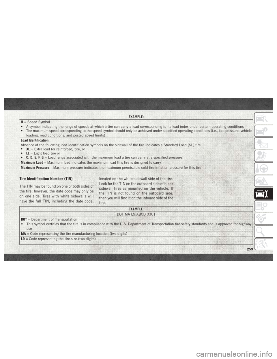
EXAMPLE:
H = Speed Symbol
• A symbol indicating the range of speeds at which a tire can carry a load corresponding to its load index under certain operating conditions
• The maximum speed corresponding to the speed symbol should only be achieved under specified operating conditions (i.e., tire pressure, vehicle
loading, road conditions, and posted speed limits)
Load Identification:
Absence of the following load identification symbols on the sidewall of the tire indicates a Standard Load (SL) tire:
• XL= Extra load (or reinforced) tire, or
• LL= Light load tire or
• C, D, E, F, G = Load range associated with the maximum load a tire can carry at a specified pressure
Maximum Load – Maximum load indicates the maximum load this tire is designed to carry
Maximum Pressure – Maximum pressure indicates the maximum permissible cold tire inflation pressure for this tire
Tire Identification Number (TIN)
The TIN may be found on one or both sides of
the tire; however, the date code may only be
on one side. Tires with white sidewalls will
have the full TIN, including the date code, located on the white sidewall side of the tire.
Look for the TIN on the outboard side of black
sidewall tires as mounted on the vehicle. If
the TIN is not found on the outboard side,
then you will find it on the inboard side of the
tire.
EXAMPLE:
DOT MA L9 ABCD 0301
DOT = Department of Transportation
• This symbol certifies that the tire is in compliance with the U.S. Department of Transportation tire safety standards and is approved for highway
use
MA = Code representing the tire manufacturing location (two digits)
L9 = Code representing the tire size (two digits)
259
Page 269 of 372

Tread Wear Indicators
Tread wear indicators are in the original
equipment tires to help you in determining
when your tires should be replaced.
These indicators are molded into the bottom
of the tread grooves. They will appear as
bands when the tread depth becomes a
1/16 of an inch (1.6 mm). When the tread is
worn to the tread wear indicators, the tire
should be replaced. Refer to “Replacement
Tires” in this section for further information.
Life Of Tire
The service life of a tire is dependent upon
varying factors including, but not limited to:
• Driving style.
• Tire pressure - Improper cold tire inflationpressures can cause uneven wear patterns
to develop across the tire tread. These ab-
normal wear patterns will reduce tread life,
resulting in the need for earlier tire replace-
ment.
• Distance driven.
• Performance tires, tires with a speed rating of V or higher, and Summer tires typically
have a reduced tread life. Rotation of these
tires per the vehicle scheduled mainte-
nance is highly recommended.
WARNING!
Tires and the spare tire should be replaced
after six years, regardless of the remaining
tread. Failure to follow this warning can
result in sudden tire failure. You could lose
control and have a collision resulting in
serious injury or death. Keep dismounted tires in a cool, dry place
with as little exposure to light as possible.
Protect tires from contact with oil, grease,
and gasoline.
Replacement Tires
The tires on your new vehicle provide a bal-
ance of many characteristics. They should be
inspected regularly for wear and correct cold
tire inflation pressures. The manufacturer
strongly recommends that you use tires
equivalent to the originals in size, quality and
performance when replacement is needed.
Refer to the paragraph on “Tread Wear Indi-
cators” in this section. Refer to the Tire and
Loading Information placard or the Vehicle
Certification Label for the size designation of
your tire. The Load Index and Speed Symbol
for your tire will be found on the original
equipment tire sidewall.
See the Tire Sizing Chart example found in
the “Tire Safety Information” section of this
manual for more information relating to the
Load Index and Speed Symbol of a tire.
Tire Tread
1 — Worn Tire
2 — New Tire
267
Page 289 of 372

MOPAR ACCESSORIES
Authentic Accessories By Mopar
• In choosing Authentic Accessories you gainfar more than expressive style, premium
protection, or extreme entertainment, you
also benefit from enhancing your vehicle
with accessories that have been thoroughly
tested and factory-approved. • The following highlights just some of the
many Authentic Ram Accessories by Mopar
featuring a fit, finish, and functionality spe-
cifically for your Ram.
• For the full line of Authentic Ram Accesso- ries by Mopar, visit your local dealership or
online at mopar.com for U.S. residents and
mopar.ca for Canadian residents. NOTE:
All parts are subject to availability.
CHROME:
• Body Side Molding
• Tubular Side Steps• Fuel Filler Door
• Cast Aluminum Wheels • Front Air Deflector• Grille
EXTERIOR:
• Bedliners • Running Boards• Bed Mat & Bed Rug
• Fiberglass Tonneau Cover • Bed Extender• Tool Box
• Roll-up Tonneau Cover • Bed Step• Sport Performance Hood
• Folding Tonneau Cover • Hitch Receiver• Hitches
• Molded Splash Guards
INTERIOR:
• Premium Carpet Mats • Door Sill Guards• Slush Mats
• Leather Seats • In-Floor Storage Locks
287
Page 316 of 372
Apple CarPlay Integration
Uconnect works seamlessly with Apple Car-
Play, the smarter, more secure way to use
your iPhone in the car, and stay focused on
the road. Use your Uconnect Touchscreen
display, the vehicle's knobs and controls, and
your voice with Siri to get access to Apple
Music, Maps, Messages, and more.
To use CarPlay, make sure you are using
iPhone 5 or later, have Siri enabled in Set-
tings, ensure your iPhone is unlocked for the
very first connection only, and then use the
following procedure:
1. Connect your iPhone to one of the mediaUSB ports in your vehicle.
NOTE:
Be sure to use the factory-provided Light-
ning cable that came with your phone, as
aftermarket cables may not work.
2. Once the device is connected, the system will display the CarPlay home screen.
Apple CarPlay should automatically
launch, but if it does not launch automati-
cally, refer to the Uconnect Owner’s
Manual Supplement for the procedure to enable the feature “AutoShow.” You can
also launch it by pressing the CarPlay
located in the “Apps” menu. If you use
Apple CarPlay frequently you can move
the app to the menu bar at the bottom of
the touchscreen. Press the “Apps” button
and locate the CarPlay app; then press
and drag the selected App to replace an
existing shortcut in the main menu bar.
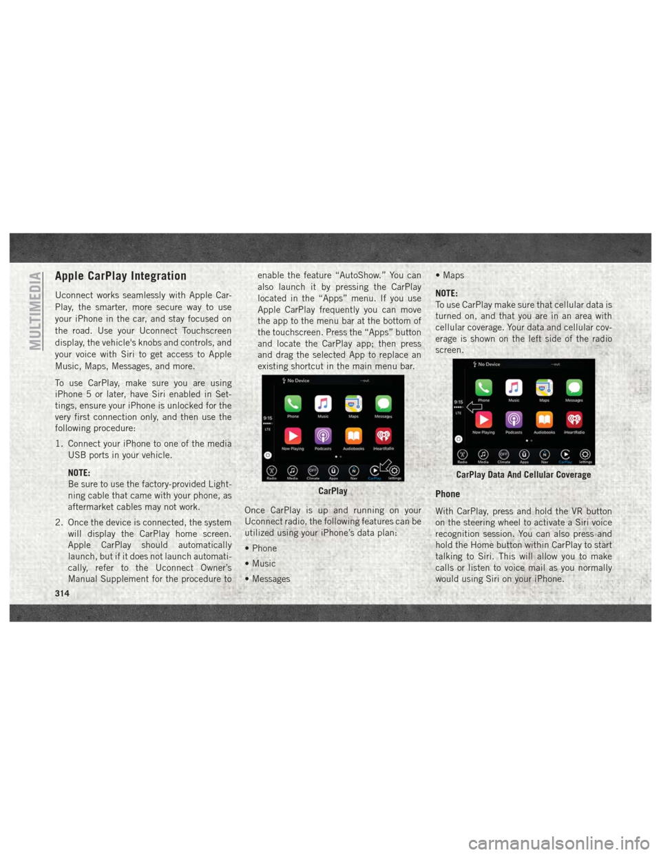
Once CarPlay is up and running on your
Uconnect radio, the following features can be
utilized using your iPhone’s data plan:
• Phone
• Music
• Messages • Maps
NOTE:
To use CarPlay make sure that cellular data is
turned on, and that you are in an area with
cellular coverage. Your data and cellular cov-
erage is shown on the left side of the radio
screen.
Phone
With CarPlay, press and hold the VR button
on the steering wheel to activate a Siri voice
recognition session. You can also press and
hold the Home button within CarPlay to start
talking to Siri. This will allow you to make
calls or listen to voice mail as you normally
would using Siri on your iPhone.
CarPlay
CarPlay Data And Cellular Coverage
MULTIMEDIA
314
Page 320 of 372
Download The Uconnect App
You’re only a few steps away from using
remote commands and other valuable ser-
vices.
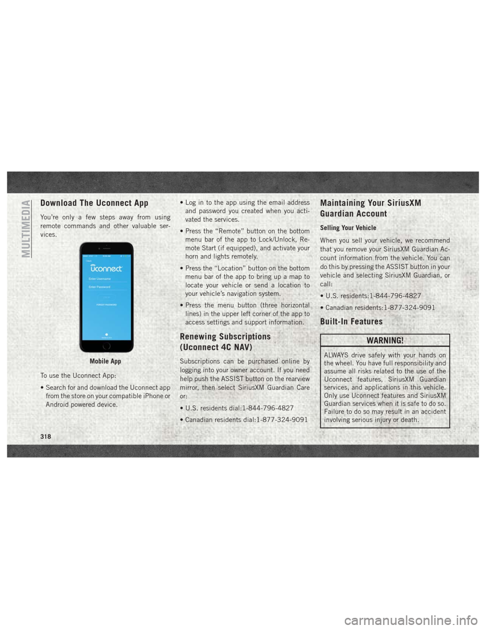
To use the Uconnect App:
• Search for and download the Uconnect appfrom the store on your compatible iPhone or
Android powered device. • Log in to the app using the email address
and password you created when you acti-
vated the services.
• Press the “Remote” button on the bottom menu bar of the app to Lock/Unlock, Re-
mote Start (if equipped), and activate your
horn and lights remotely.
• Press the “Location” button on the bottom menu bar of the app to bring up a map to
locate your vehicle or send a location to
your vehicle’s navigation system.
• Press the menu button (three horizontal lines) in the upper left corner of the app to
access settings and support information.
Renewing Subscriptions
(Uconnect 4C NAV)
Subscriptions can be purchased online by
logging into your owner account. If you need
help push the ASSIST button on the rearview
mirror, then select SiriusXM Guardian Care
or:
• U.S. residents dial:1-844-796-4827
• Canadian residents dial:1-877-324-9091
Maintaining Your SiriusXM
Guardian Account
Selling Your Vehicle
When you sell your vehicle, we recommend
that you remove your SiriusXM Guardian Ac-
count information from the vehicle. You can
do this by pressing the ASSIST button in your
vehicle and selecting SiriusXM Guardian, or
call:
• U.S. residents:1-844-796-4827
• Canadian residents:1-877-324-9091
Built-In Features
WARNING!
ALWAYS drive safely with your hands on
the wheel. You have full responsibility and
assume all risks related to the use of the
Uconnect features, SiriusXM Guardian
services, and applications in this vehicle.
Only use Uconnect features and SiriusXM
Guardian services when it is safe to do so.
Failure to do so may result in an accident
involving serious injury or death.Mobile App
MULTIMEDIA
318
Page 321 of 372

WARNING!
• ALWAYS obey traffic laws and pay atten-tion to the road. Some features are lim-
ited while the vehicle is in motion. Some
services, including SOS, will NOT work
without a subscription and an operable
network connection.
• Ignoring the rearview mirror light could
mean you may not have SOS Call service
if needed. If the rearview mirror light is
illuminated, have an authorized dealer
service the SOS Call system immedi-
ately.
• The Occupant Restraint Controller
(ORC) turns on the Air Bag Warning
Light on the instrument panel if a mal-
function is detected in any part of the
airbag system. If the Air Bag Warning
Light is illuminated, the air bag system
may not be working properly and the
SOS Call system may not send a signal to
a SOS Call operator if an air bag is
deployed. If the Air Bag Warning Light is
illuminated, have an authorized dealer
service your vehicle immediately.
WARNING!
• If anyone in the vehicle could be indanger (e.g., fire or smoke is visible,
dangerous road conditions or location),
do not wait for voice contact from a SOS
Call operator. All occupants should exit
the vehicle immediately and move to a
safe location.
• The SOS Call system is embedded into
the vehicle’s electrical system. Do not
add aftermarket electrical equipment to
the vehicle’s electrical system. This may
prevent your vehicle from sending a sig-
nal to initiate an emergency call. To
avoid interference that can cause the
SOS Call system to fail, never add after-
market equipment (e.g., two-way mobile
radio, CB radio, data recorder, etc.) to
your vehicle’s electrical system or
modify the antennas on your vehicle.
• IF YOUR VEHICLE LOSES BATTERY
POWER FOR ANY REASON (INCLUD-
ING DURING OR AFTER AN ACCI-
DENT), the Uconnect features, apps,
and SiriusXM Guardian services, among
others, will not operate. NOTE:
Your vehicle may be transmitting data as
authorized by the subscriber.
1.
ASSIST Call (4C NAV) —
The rearview mirror
contains an ASSIST button, allowing you to
speak to a call center agent for support:
• Roadside Assistance Call — If you get a
flat tire, or need a tow, you’ll be con-
nected to someone who can help any-
time. Additional fees may apply. Addi-
tional information in this section.
SOS Call Button And ASSIST
1 — SOS Call Button
2 — ASSIST Button
319
Page 322 of 372
•Uconnect Care — In vehicle support for
Uconnect Apps and Features.
• SiriusXM Guardian Care — In vehicle
support for SiriusXM Guardian ser-
vices.
• Vehicle Care — Total support for your
FCA US LLC vehicle.
NOTE:
In order to provide SiriusXM Guardian Ser-
vices to you, we may record and monitor your
conversations with Roadside Assistance,
Uconnect Care, SiriusXM Guardian Care, or
Vehicle Care, whether such conversations are
initiated through the SiriusXM Guardian ser-
vices in your vehicle, your device, or via a
landline device, and may share information
obtained through such recording and moni-
toring in accordance with regulatory require-
ments. You acknowledge, agree, and consent
to any recording, monitoring or sharing of
information obtained through any such call
recordings. 2.
Emergency SOS Call (If Equipped) — The
rearview mirror contains a SOS Call but-
ton that, when pressed, may place a call
from your vehicle to a SiriusXM Guardian
Care operator, who can connect you to
emergency service operators, to request
help from local police, fire or ambulance
personnel. If this button is accidentally
pressed, you will have ten seconds to stop
the call. To cancel, press the SOS Call
button again or press the “Cancel” button
shown on the touchscreen. After ten sec-
onds has passed, the SOS call will be
placed and only the SOS Call operator can
cancel it. The LED light on the rearview
mirror will turn green once a connection to
a SOS Call operator has been made. The
green LED light will turn off once the SOS
Call is terminated. Have an authorized
dealer service the vehicle if the rearview
mirror light is continuously red. On
equipped vehicles, this feature requires a
functioning electrical system, a subscrip-
tion, and an operable network connection. If a connection is made between a SOS Call
operator and your vehicle, you understand
and agree that SOS Call operators will stay
on the line, even after you connect with
emergency services. The Emergency ser-
vices operator may, like any other emer-
gency call, record conversations and
sounds in and near your vehicle upon
connection.
3. Theft Alarm Notification — The Theft Alarm
Notification feature notifies you via email
or text (SMS) message when the vehicle’s
factory-installed security alarm system
has been set-off. There are a number of
reasons why your alarm may have been
triggered, one of which could be that your
vehicle was stolen. If so, please see the
details of the Stolen Vehicle Assistance
service below. When you activate, Theft
Alarm Notification is automatically set to
send you an email at the email address
you provide should the alarm go off. You
may also opt to have a text message sent
to your device.
MULTIMEDIA
320