RAM 1500 2023 User Guide
Manufacturer: RAM, Model Year: 2023, Model line: 1500, Model: RAM 1500 2023Pages: 416, PDF Size: 20.59 MB
Page 11 of 416

9
SYMBOLS KEY
If you do not read the entire Owner’s Manual, you may miss important information.
Observe all Cautions and Warnings.
VAN CONVERSIONS/CAMPERS
The New Vehicle Limited Warranty does not apply to body modifications or special
equipment installed by van conversion/camper manufacturers/body builders.
US residents refer to the Warranty Information, Section 2.1.C. Canadian residents refer to
the “What Is Not Covered” section of the Warranty Information. Such equipment includes
video monitors, DVD/Blu-Ray™, heaters, stoves, refrigerators, etc. For warranty coverage
and service on these items, contact the applicable manufacturer.
CONSUMER INFORMATION — TRUCK-CAMPER LOADING
This information is provided in fulfillment of the requirement by the United States
Government, Department of Transportation, National Highway Traffic Safety
Administration, that “every manufacturer of trucks that are capable of accommodating
slide-in campers, manufactured on or after April 1, 1973 shall provide... at the time of
original purchase to the first person who purchases the truck”... information on Truck
Camper Loading.
A slide-in camper document is provided in your vehicle’s glove compartment that contains
your Vehicle Identification Number, truck model, cargo weight rating, and the forward/
rearward limit of a camper. To obtain additional dimensional and technical specifications
for your vehicle, please visit https://www.ramtrucks.com.
WARNING!
These statements apply to operating procedures that
could result in a collision, bodily injury and/or death.
CAUTION! These statements apply to procedures that could result in
damage to your vehicle.
NOTE: A suggestion which will improve installation, operation,
and reliability. If not followed, may result in damage.
TIP: General ideas/solutions/suggestions on easier use of the
product or functionality.
PAGE REFERENCE ARROW
Follow this reference for additional information on a
particular feature.
FOOTNOTE Supplementary and relevant information pertaining to
the topic.
1
23_DT_OM_EN_USC_t.book Page 9
Page 12 of 416
10
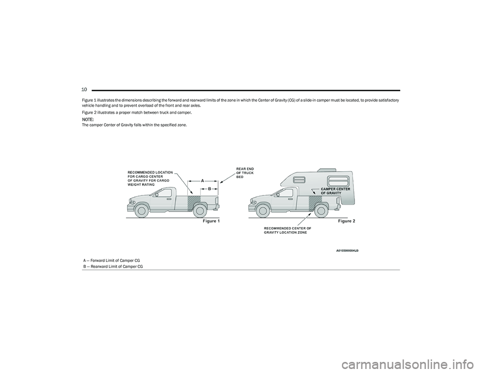
Figure 1 illustrates the dimensions describing the forward and rearward limits of the zone in which the Center of Gravity (CG) of a slide-in camper must be located, to provide satisfactory
vehicle handling and to prevent overload of the front and rear axles.
Figure 2 illustrates a proper match between truck and camper.
NOTE:The camper Center of Gravity falls within the specified zone.A — Forward Limit of Camper CG
B — Rearward Limit of Camper CG
23_DT_OM_EN_USC_t.book Page 10
Page 13 of 416
11
When the truck is used to carry a slide-in camper, the total cargo load of the truck consists
of the manufacturer’s camper weight figure, the weight of installed additional camper
equipment not included in the manufacturer’s camper weight figure, the weight of camper
cargo, and the weight of passengers in the camper. The total cargo load should not exceed
the truck’s cargo weight rating and the camper’s CG should fall within the truck’s
recommended CG zone when installed.
Secure loose items to prevent weight shifts that could affect the balance of your vehicle.
When the truck camper is loaded, drive to a scale and weigh the front and rear wheels
separately, to determine axle loads. Individual axle loads should not exceed either of the
Gross Axle Weight Ratings (GAWR). The total of the axle loads should not exceed the Gross
Vehicle Weight Rating (GVWR). If weight ratings are exceeded, move or remove items to
get the total weight below the ratings.
NOTE:These ratings are also provided on the Vehicle Certification Label located on the driver’s
side B-pillar. See Úpage 172 for more information.
For any additional instructions, please contact your conversion/camper manufacturer or
an authorized dealer.
VEHICLE MODIFICATIONS/ALTERATIONS
SYMBOL GLOSSARY
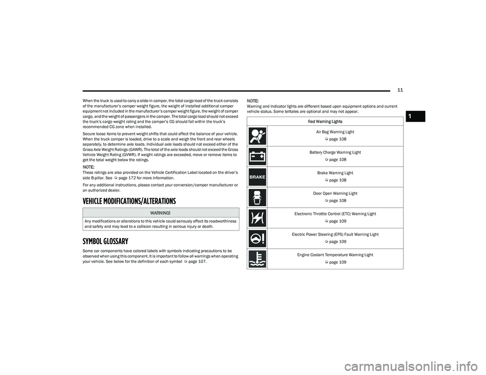
Some car components have colored labels with symbols indicating precautions to be
observed when using this component. It is important to follow all warnings when operating
your vehicle. See below for the definition of each symbol
Úpage 107.
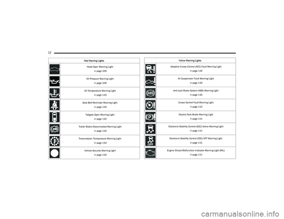
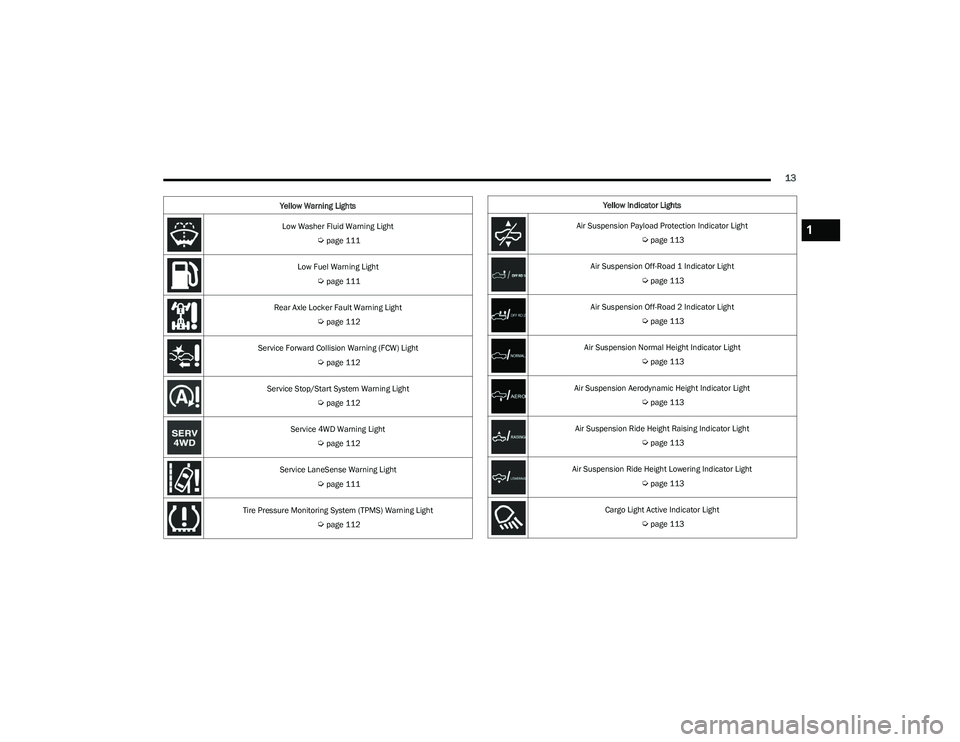
NOTE:Warning and Indicator lights are different based upon equipment options and current
vehicle status. Some telltales are optional and may not appear.
WARNING!
Any modifications or alterations to this vehicle could seriously affect its roadworthiness
and safety and may lead to a collision resulting in serious injury or death.
Red Warning Lights
Air Bag Warning Light
Úpage 108
Battery Charge Warning Light
Úpage 108
Brake Warning Light
Úpage 108
Door Open Warning Light
Úpage 108
Electronic Throttle Control (ETC) Warning Light
Úpage 109
Electric Power Steering (EPS) Fault Warning Light
Úpage 109
Engine Coolant Temperature Warning Light
Úpage 109
1
23_DT_OM_EN_USC_t.book Page 11
Page 14 of 416
12
Hood Open Warning Light
Úpage 109
Oil Pressure Warning Light
Úpage 109
Oil Temperature Warning Light
Úpage 110
Seat Belt Reminder Warning Light
Úpage 110
Tailgate Open Warning Light
Úpage 110
Trailer Brake Disconnected Warning Light
Úpage 110
Transmission Temperature Warning Light
Úpage 110
Vehicle Security Warning Light
Úpage 110
Red Warning Lights
Yellow Warning Lights
Adaptive Cruise Control (ACC) Fault Warning Light
Úpage 110
Air Suspension Fault Warning Light
Úpage 110
Anti-Lock Brake System (ABS) Warning Light
Úpage 110
Cruise Control Fault Warning Light
Úpage 112
Electric Park Brake Warning Light
Úpage 111
Electronic Stability Control (ESC) Active Warning Light
Úpage 111
Electronic Stability Control (ESC) OFF Warning Light
Úpage 111
Engine Check/Malfunction Indicator Warning Light (MIL)
Úpage 111
23_DT_OM_EN_USC_t.book Page 12
Page 15 of 416
13
Low Washer Fluid Warning Light
Úpage 111
Low Fuel Warning Light
Úpage 111
Rear Axle Locker Fault Warning Light
Úpage 112
Service Forward Collision Warning (FCW) Light
Úpage 112
Service Stop/Start System Warning Light
Úpage 112
Service 4WD Warning Light
Úpage 112
Service LaneSense Warning Light
Úpage 111
Tire Pressure Monitoring System (TPMS) Warning Light
Úpage 112
Yellow Warning Lights
Yellow Indicator Lights
Air Suspension Payload Protection Indicator Light
Úpage 113
Air Suspension Off-Road 1 Indicator Light
Úpage 113
Air Suspension Off-Road 2 Indicator Light
Úpage 113
Air Suspension Normal Height Indicator Light
Úpage 113
Air Suspension Aerodynamic Height Indicator Light
Úpage 113
Air Suspension Ride Height Raising Indicator Light
Úpage 113
Air Suspension Ride Height Lowering Indicator Light
Úpage 113
Cargo Light Active Indicator Light
Úpage 113
1
23_DT_OM_EN_USC_t.book Page 13
Page 16 of 416
14
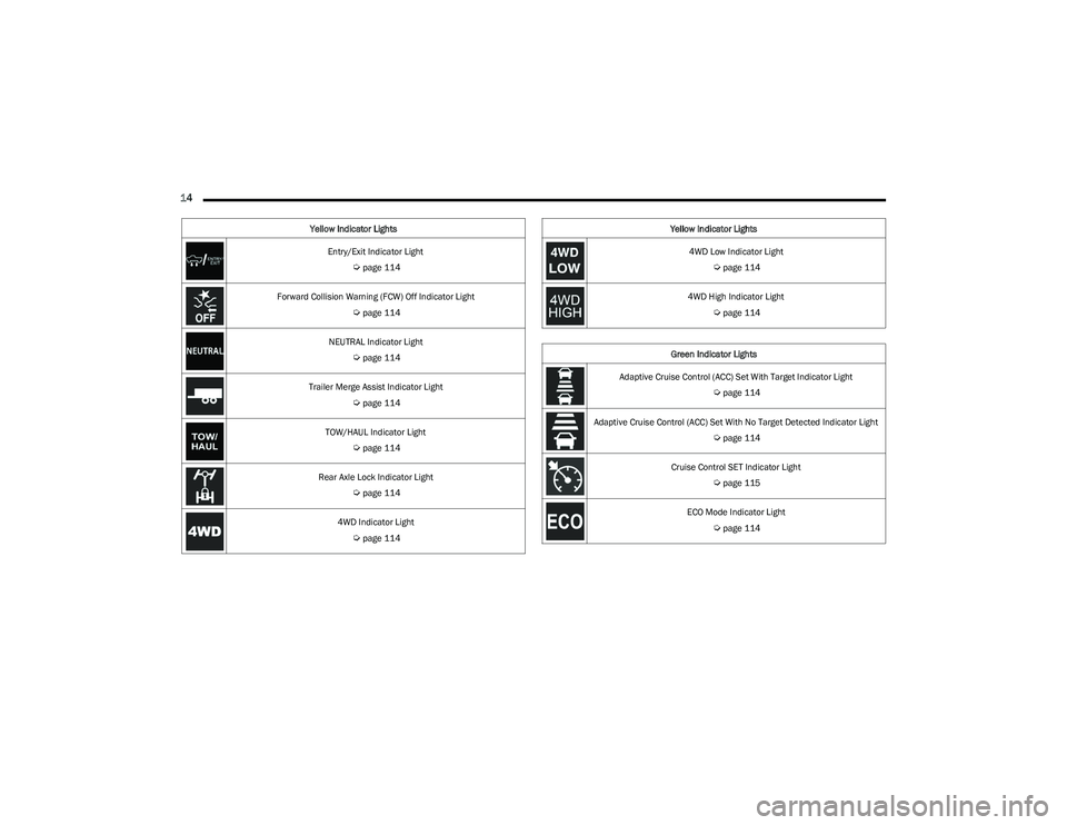
Entry/Exit Indicator Light
Úpage 114
Forward Collision Warning (FCW) Off Indicator Light
Úpage 114
NEUTRAL Indicator Light
Úpage 114
Trailer Merge Assist Indicator Light
Úpage 114
TOW/HAUL Indicator Light
Úpage 114
Rear Axle Lock Indicator Light
Úpage 114
4WD Indicator Light
Úpage 114
Yellow Indicator Lights
4WD Low Indicator Light
Úpage 114
4WD High Indicator Light
Úpage 114
Green Indicator Lights
Adaptive Cruise Control (ACC) Set With Target Indicator Light
Úpage 114
Adaptive Cruise Control (ACC) Set With No Target Detected Indicator Light
Úpage 114
Cruise Control SET Indicator Light
Úpage 115
ECO Mode Indicator Light
Úpage 114
Yellow Indicator Lights
23_DT_OM_EN_USC_t.book Page 14
Page 17 of 416
15
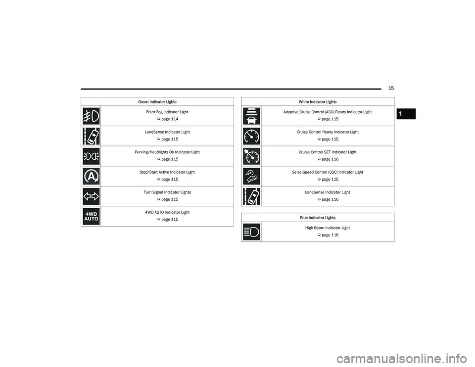
Front Fog Indicator Light
Úpage 114
LaneSense Indicator Light
Úpage 115
Parking/Headlights On Indicator Light
Úpage 115
Stop/Start Active Indicator Light
Úpage 115
Turn Signal Indicator Lights
Úpage 115
4WD AUTO Indicator Light
Úpage 115
Green Indicator Lights
White Indicator Lights
Adaptive Cruise Control (ACC) Ready Indicator Light
Úpage 115
Cruise Control Ready Indicator Light
Úpage 115
Cruise Control SET Indicator Light
Úpage 116
Selec-Speed Control (SSC) Indicator Light
Úpage 115
LaneSense Indicator Light
Úpage 116
Blue Indicator Lights High Beam Indicator Light
Úpage 116
1
23_DT_OM_EN_USC_t.book Page 15
Page 18 of 416
16
GETTING TO KNOW YOUR VEHICLE
KEYS
KEY FOB
Your vehicle is equipped with a key fob which supports
Passive Entry, Remote Keyless Entry (RKE), Keyless
Enter ‘n Go™ (if equipped), remote air suspension
lowering (if equipped), and Remote Start (if equipped).
The key fob allows you to lock or unlock all doors, tailgate,
and the RamBox (if equipped) as well as activate the Panic
Alarm from distances up to approximately 66 ft (20 m). The key fob does not need to be pointed at the vehicle to
activate the system. The key fob also contains an
emergency key, which is stored in the rear of the key fob.
NOTE:
The key fob’s wireless signal may be blocked if the key
fob is located next to a mobile phone, laptop, or other
electronic device. This may result in poor performance.
If your vehicle is equipped with a Wireless Charging
Pad, the key fob may not be detected if it is placed
within 6 inches (15 cm) of the pad
Úpage 68.
With the ignition in the ON position and the vehicle
moving at 2 mph (4 km/h), all RKE commands are
disabled.
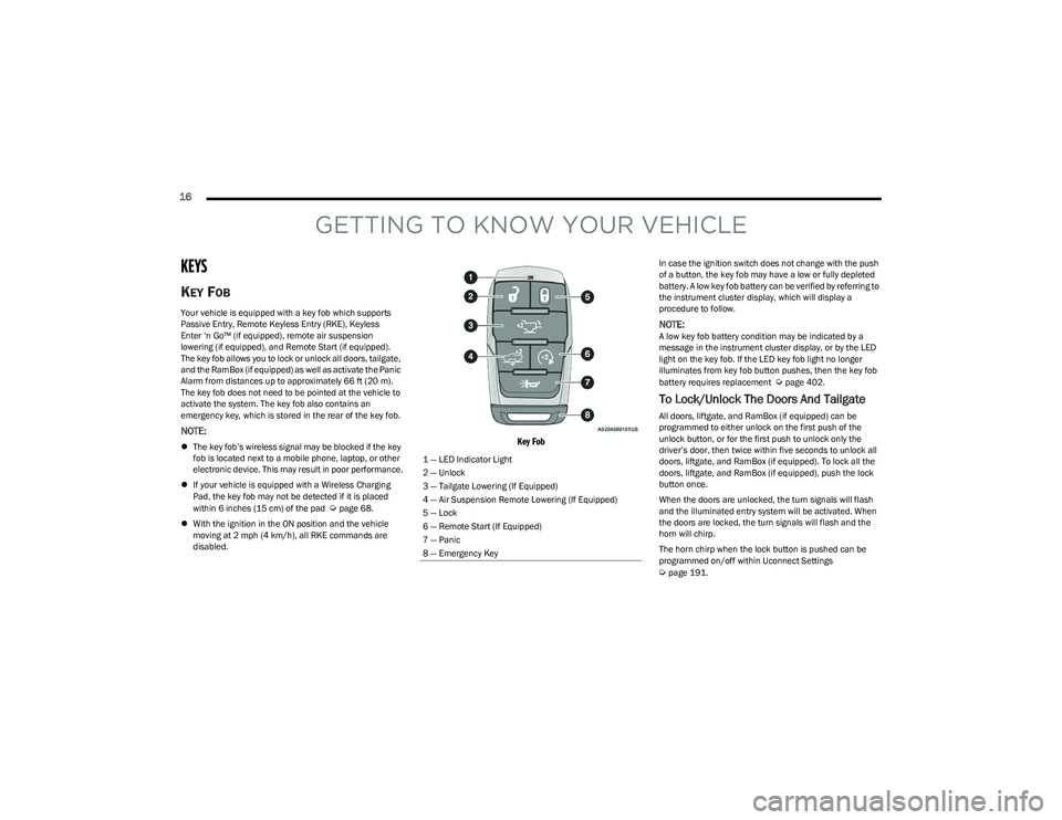
Key Fob
In case the ignition switch does not change with the push
of a button, the key fob may have a low or fully depleted
battery. A low key fob battery can be verified by referring to
the instrument cluster display, which will display a
procedure to follow.
NOTE:A low key fob battery condition may be indicated by a
message in the instrument cluster display, or by the LED
light on the key fob. If the LED key fob light no longer
illuminates from key fob button pushes, then the key fob
battery requires replacement
Úpage 402.
To Lock/Unlock The Doors And Tailgate
All doors, liftgate, and RamBox (if equipped) can be
programmed to either unlock on the first push of the
unlock button, or for the first push to unlock only the
driver’s door, then twice within five seconds to unlock all
doors, liftgate, and RamBox (if equipped). To lock all the
doors, liftgate, and RamBox (if equipped), push the lock
button once.
When the doors are unlocked, the turn signals will flash
and the illuminated entry system will be activated. When
the doors are locked, the turn signals will flash and the
horn will chirp.
The horn chirp when the lock button is pushed can be
programmed on/off within Uconnect Settings
Úpage 191.
1 — LED Indicator Light
2 — Unlock
3 — Tailgate Lowering (If Equipped)
4 — Air Suspension Remote Lowering (If Equipped)
5 — Lock
6 — Remote Start (If Equipped)
7 — Panic
8 — Emergency Key
23_DT_OM_EN_USC_t.book Page 16
Page 19 of 416
GETTING TO KNOW YOUR VEHICLE17
Using The Panic Feature
To turn the Panic feature on or off, push the Panic button
on the key fob. When the Panic feature is activated, the
turn signals will flash, the horn may pulse on and off
(if equipped with horn alarm), and the interior lights will
turn on.
The Panic feature will stay on for three minutes unless you
turn it off by either pushing the Panic button a second time
or driving the vehicle at a speed of 15 mph (24 km/h) or
greater.
NOTE:
The interior lights will turn off if you place the ignition in
the ON/RUN position while the Panic feature is
activated. However, the exterior lights and horn
(if equipped with horn alarm) will remain on.
You may need to be less than 35 ft (11 m) from the
vehicle when using the key fob to turn off the Panic
feature due to the radio frequency noises emitted by
the system.
Key Left Vehicle Feature
If a valid key fob is no longer detected inside the vehicle
while the vehicle’s ignition system is in the ON/RUN or
START position, the message “Key Fob Has Left The
Vehicle” will be shown in the instrument cluster display
along with an interior chime. An exterior audible and visual
alert will also be activated to warn the driver.
The vehicle’s horn will rapidly chirp three times along with
a single flash of the vehicle’s exterior lights.
NOTE:
The doors have to be open and then closed in order for
the vehicle to detect a key fob; the Key Left Vehicle
feature will not activate until all of the doors are closed.
These alerts will not be activated in situations where
the vehicle’s engine is left running with the key fob
inside.
Air Suspension (Remote Lowering Of The
Vehicle) — If Equipped
For easy entry and loading, your vehicle can be
lowered by pushing the key fob air suspension
lowering button two times. When air
suspension lowering is requested using the key
fob, the vehicle will send a series of chirps and flashes to
alert the customer that the operation has begun and will
continue these alerts until it successfully lowers.
The following conditions must be met for the vehicle to
lower remotely:
The vehicle must not already be in Entry/Exit ride
height.
The vehicle battery must be fully charged.
All doors must be closed.
The key fob must be out of the vehicle.
Gear selector must be in PARK.
NOTE:Ensure the vehicle is clear of all objects, pets, and people
prior to remote lowering. Canceling Remote Lowering
Vehicle lowering can be canceled at anytime. When
vehicle lowering is canceled, the vehicle will raise to the
next defined level and lock out the remote lowering
feature for five seconds until a new request is made.
To cancel vehicle lowering, push the key fob air
suspension lowering button one time during the lowering
process. When vehicle lowering is canceled, the horn will
chirp two times and the turn signal lamps will flash four
times. Once raising is completed, the horn will chirp
one time.
NOTE:More information on air suspension is provided later in
this manual, see Úpage 134.
Replacing The Battery In The Key Fob
The replacement battery model is one CR2450 battery.
NOTE:
Customers are recommended to use a battery
obtained from Mopar®. Aftermarket coin battery
dimensions may not meet the original OEM coin battery
dimensions.
Perchlorate Material — special handling may apply. See
www.dtsc.ca.gov/hazardouswaste/perchlorate for
further information.
2
23_DT_OM_EN_USC_t.book Page 17
Page 20 of 416

18GETTING TO KNOW YOUR VEHICLE
Do not touch the battery terminals that are on the back
housing or the printed circuit board.
Do not replace the coin battery if the LED on the key fob
above the top row buttons blinks when a button is
pressed. The coin battery should last a minimum of
three years with normal vehicle usage.
1. Remove the emergency key (1) by pushing the emergency key release button (2) on the side of the
key fob, and pulling the emergency key out with your
other hand.
Emergency Key Removal
2. Hold the key fob with the button side facing down, and locate the small rectangular gap on the left side
between the housing and the back cover of the key
fob. Use a small screwdriver (or similar tool) to pry
open the left side of the fob cover while applying
pressure until the cover snaps open.
3. Next, locate the gap on the right side of the key fob, which is positioned farther to the edge than the left
side gap. Pry open the right side, and remove the
back cover.
4. Remove the battery by using your thumb to slide the battery downward and back toward the key ring.
Key Fob Battery Location
NOTE:
When replacing the battery, ensure the (+) sign on the
battery is facing upward. Avoid touching the new battery
with your fingers. Skin oils may cause battery deterio -
ration. If you touch a battery, clean it with rubbing alcohol. 5. Replace the battery by using your thumb to push
down and slide the battery under the small lip on the
top edge of the opening.
Key Fob Battery Replacement
6. To assemble the key fob case, line up the top edge of the back cover with the top of the fob, and press the
edges into the interlocking hinges until all edges snap
together with no large visual gaps.
7. Reinsert the emergency key until it locks into place.
NOTE:The key fob battery should only be replaced by qualified
technicians. If the battery requires replacement, see an
authorized dealer.
1 — Emergency Key
2 — Emergency Key Release Button
23_DT_OM_EN_USC_t.book Page 18