service Ram 2500 2020 Owner's Guide
[x] Cancel search | Manufacturer: RAM, Model Year: 2020, Model line: 2500, Model: Ram 2500 2020Pages: 553, PDF Size: 21.99 MB
Page 139 of 553
GETTING TO KNOW YOUR INSTRUMENT PANEL137
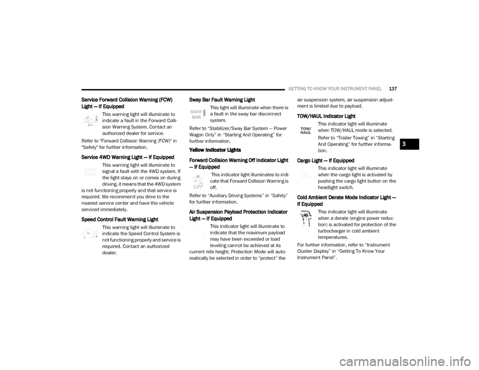
Service Forward Collision Warning (FCW)
Light — If Equipped
This warning light will illuminate to
indicate a fault in the Forward Colli-
sion Warning System. Contact an
authorized dealer for service.
Refer to "Forward Collision Warning (FCW)" in
"Safety" for further information.
Service 4WD Warning Light — If Equipped
This warning light will illuminate to
signal a fault with the 4WD system. If
the light stays on or comes on during
driving, it means that the 4WD system
is not functioning properly and that service is
required. We recommend you drive to the
nearest service center and have the vehicle
serviced immediately.
Speed Control Fault Warning Light
This warning light will illuminate to
indicate the Speed Control System is
not functioning properly and service is
required. Contact an authorized
dealer.
Sway Bar Fault Warning Light
This light will illuminate when there is
a fault in the sway bar disconnect
system.
Refer to “Stabilizer/Sway Bar System — Power
Wagon Only” in “Starting And Operating” for
further information.
Yellow Indicator Lights
Forward Collision Warning Off Indicator Light
— If Equipped
This indicator light illuminates to indi -
cate that Forward Collision Warning is
off.
Refer to “Auxiliary Driving Systems” in “Safety”
for further information.
Air Suspension Payload Protection Indicator
Light — If Equipped
This indicator light will illuminate to
indicate that the maximum payload
may have been exceeded or load
leveling cannot be achieved at its
current ride height. Protection Mode will auto -
matically be selected in order to “protect” the air suspension system, air suspension adjust
-
ment is limited due to payload.
TOW/HAUL Indicator Light
This indicator light will illuminate
when TOW/HAUL mode is selected.
Refer to “Trailer Towing” in “Starting
And Operating” for further informa -
tion.
Cargo Light — If Equipped
This indicator light will illuminate
when the cargo light is activated by
pushing the cargo light button on the
headlight switch.
Cold Ambient Derate Mode Indicator Light —
If Equipped
This indicator light will illuminate
when a derate (engine power reduc -
tion) is activated for protection of the
turbocharger in cold ambient
temperatures.
For further information, refer to “Instrument
Cluster Display” in “Getting To Know Your
Instrument Panel”.
3
20_DJD2_OM_EN_USC_t.book Page 137
Page 141 of 553

GETTING TO KNOW YOUR INSTRUMENT PANEL139
4WD Lock Indicator Light
This light alerts the driver that the
vehicle is in the four-wheel drive LOCK
mode. The front and rear driveshafts
are mechanically locked together,
forcing the front and rear wheels to rotate at the
same speed.
Refer to “Four-Wheel Drive Operation” in
“Starting And Operating” for further information
on four-wheel drive operation and proper use.
4WD Low Indicator Light — If Equipped
This light alerts the driver that the
vehicle is in the four-wheel drive LOW
mode. The front and rear driveshafts
are mechanically locked together
forcing the front and rear wheels to rotate at the
same speed. Low range provides a greater gear
reduction ratio to provide increased torque at
the wheels.
Refer to “Four-Wheel Drive Operation — If
Equipped” in “Starting And Operating” for
further information on four-wheel drive opera -
tion and proper use.
4WD High Indicator Light — If Equipped
This light alerts the driver that the
vehicle is in the four-wheel drive HIGH
mode. The front and rear driveshafts
are mechanically locked together
forcing the front and rear wheels to rotate at the
same speed.
NEUTRAL Indicator Light — If Equipped
This light alerts the driver that the
4WD power transfer case is in the
NEUTRAL mode and the front and rear
driveshafts are disengaged from the
powertrain.
Low Diesel Exhaust Fluid (DEF) Indicator
Light — If Equipped
The Low Diesel Exhaust Fluid (DEF)
Indicator will illuminate if the vehicle
is low on Diesel Exhaust Fluid (DEF).
Refer to “Starting And Operating” for
further information.
Wait To Start Light — If Equipped
This indicator light will illuminate for
approximately two seconds when the
ignition is turned to the RUN position.
Its duration may be longer based on colder operating conditions. Vehicle will not
initiate start until telltale is no longer displayed.
Refer to “Starting The Engine” in “Starting And
Operating” for further information.
NOTE:
The “Wait To Start” telltale may not illuminate if
the intake manifold temperature is warm
enough.
Water In Fuel Indicator Light — If Equipped
The “Water In Fuel Indicator Light” will
illuminate when there is water
detected in the fuel filter. If this light
remains on, DO NOT start the vehicle
before you drain the water from the fuel filter to
prevent engine damage.
Refer to the “Draining Fuel/Water Separator
Filter” section in “Dealer Service” in “Servicing
And Maintenance” for further information.
3
20_DJD2_OM_EN_USC_t.book Page 139
Page 143 of 553

GETTING TO KNOW YOUR INSTRUMENT PANEL141
Cruise Control Set Indicator Light — If
Equipped
This indicator light will illuminate
when the cruise control is set to the
desired speed. Refer to “Speed
Control” in “Starting And Operating”
for further information.
White Indicator Lights
Adaptive Cruise Control (ACC) Ready Light —
If Equipped
This light will illuminate when the
vehicle equipped with Adaptive Cruise
Control (ACC) has been turned on but
not set.
Refer to “Adaptive Cruise Control (ACC) — If
Equipped” in “Starting And Operating” for
further information.
Cruise Control Ready Indicator
This indicator light will illuminate
when the cruise control is ready, but
not set. Refer to “Speed Control” in
“Starting And Operating” for further
information.
Hill Descent Control (HDC) Indicator Light — If
Equipped
This indicator shows when the Hill
Descent Control (HDC) feature is
turned on. The lamp will be on solid
when HDC is armed. HDC can only be
armed when the transfer case is in the “4WD
LOW” position and the vehicle speed is less
then 20 mph (32 km/h). If these conditions are
not met while attempting to use the HDC
feature, the HDC indicator light will flash on/off.
LaneSense Indicator Light — If Equipped
When the LaneSense system is ON,
but not armed, the LaneSense indi -
cator light illuminates solid white. This
occurs when only left, right, or neither
lane line has been detected. If a single lane line
is detected, the system is ready to provide only
visual warnings if an unintentional lane depar -
ture occurs on the detected lane line.
Refer to “LaneSense — If Equipped” in “Starting
And Operating” for further information.
Blue Indicator Lights
High Beam Indicator Light
This indicator light will illuminate to
indicate that the high beam head -
lights are on. With the low beams acti -
vated, push the multifunction lever
forward (toward the front of the vehicle) to turn
on the high beams. Pull the multifunction lever
rearward (toward the rear of the vehicle) to turn
off the high beams. If the high beams are off,
pull the lever toward you for a temporary high
beam on, "flash to pass" scenario.
ONBOARD DIAGNOSTIC SYSTEM — OBD II
Your vehicle is equipped with a sophisticated
Onboard Diagnostic system called OBD II. This
system monitors the performance of the emis -
sions, engine, and transmission control
systems. When these systems are operating
properly, your vehicle will provide excellent
performance and fuel economy, as well as
engine emissions well within current govern -
ment regulations.
If any of these systems require service, the OBD
II system will turn on the Malfunction Indicator
Light (MIL). It will also store diagnostic codes
and other information to assist your service
3
20_DJD2_OM_EN_USC_t.book Page 141
Page 144 of 553
142GETTING TO KNOW YOUR INSTRUMENT PANEL
technician in making repairs. Although your
vehicle will usually be drivable and not need
towing, see an authorized dealer for service as
soon as possible.
Onboard Diagnostic System (OBD II)
Cybersecurity
Your vehicle is required to have an Onboard
Diagnostic system (OBD II) and a connection
port to allow access to information related to
the performance of your emissions controls.
Authorized service technicians may need to
access this information to assist with the diag-
nosis and service of your vehicle and emissions
system. For further information, refer to “Cybersecurity”
in “Multimedia”.
EMISSIONS INSPECTION AND
MAINTENANCE PROGRAMS
In some localities, it may be a legal requirement
to pass an inspection of your vehicle's emis
-sions control system. Failure to pass could
prevent vehicle registration.
For states that require an Inspection
and Maintenance (I/M), this check
verifies the “Malfunction Indicator
Light (MIL)” is functioning and is not
on when the engine is running, and that the
OBD II system is ready for testing.
Normally, the OBD II system will be ready. The
OBD II system may not be ready if your vehicle
was recently serviced, recently had a depleted
battery or a battery replacement. If the OBD II
system should be determined not ready for the
I/M test, your vehicle may fail the test.
Your vehicle has a simple ignition actuated test,
which you can use prior to going to the test
station. To check if your vehicle's OBD II system
is ready, you must do the following:
1. Cycle the ignition switch to the ON position, but do not crank or start the engine.
NOTE:
If you crank or start the engine, you will have to
start this test over.
CAUTION!
Prolonged driving with the MIL on could
cause further damage to the emission
control system. It could also affect fuel
economy and driveability. The vehicle must
be serviced before any emissions tests can
be performed.
If the MIL is flashing while the vehicle is
running, severe catalytic converter damage
and power loss will soon occur. Immediate
service is required.
WARNING!
ONLY an authorized service technician
should connect equipment to the OBD II
connection port in order to read the VIN,
diagnose, or service your vehicle.
If unauthorized equipment is connected to
the OBD II connection port, such as a
driver-behavior tracking device, it may:
Be possible that vehicle systems, including safety related systems, could
be impaired or a loss of vehicle control
could occur that may result in an acci -
dent involving serious injury or death.
Access, or allow others to access, infor -
mation stored in your vehicle systems,
including personal information.
20_DJD2_OM_EN_USC_t.book Page 142
Page 145 of 553
GETTING TO KNOW YOUR INSTRUMENT PANEL143
2. As soon as you cycle the ignition switch to
the ON position, you will see the “Malfunc -
tion Indicator Light (MIL)” symbol come on
as part of a normal bulb check.
3. Approximately 15 seconds later, one of two things will happen:
The MIL will flash for about 10 seconds
and then return to being fully illuminated
until you turn OFF the ignition or start the
engine. This means that your vehicle's
OBD II system is not ready and you
should not proceed to the I/M station.
The MIL will not flash at all and will
remain fully illuminated until you place
the ignition in the off position or start the
engine. This means that your vehicle's
OBD II system is ready and you can
proceed to the I/M station. If your OBD II system is not ready,
you should
see an authorized dealer or repair facility. If your
vehicle was recently serviced or had a battery
failure or replacement, you may need to do
nothing more than drive your vehicle as you
normally would in order for your OBD II system
to update. A recheck with the above test routine
may then indicate that the system is now ready.Regardless of whether your vehicle's OBD II
system is ready or not, if the MIL is illuminated
during normal vehicle operation you should
have your vehicle serviced before going to the I/
M station. The I/M station can fail your vehicle
because the MIL is on with the engine running.
3
20_DJD2_OM_EN_USC_t.book Page 143
Page 147 of 553
SAFETY145
ABS is designed to function with the Original
Equipment Manufacturer (OEM) tires. Modifica -
tion may result in degraded ABS performance.
Anti-Lock Brake Warning Light
The yellow “Anti-Lock Brake Warning Light” will
turn on when the ignition is placed in the ON/
RUN mode and may stay on for as long as four
seconds.
If the “Anti-Lock Brake Warning Light” remains
on or comes on while driving, it indicates that
the anti-lock portion of the brake system is not
functioning and that service is required.
However, the conventional brake system will
continue to operate normally if the “Anti-Lock
Brake Warning Light” is on.
If the “Anti-Lock Brake Warning Light” is on, the
brake system should be serviced as soon as
possible to restore the benefits of anti-lock
brakes. If the “Anti-Lock Brake Warning Light”
does not come on when the ignition is placed in
the ON/RUN mode, have the light repaired as
soon as possible.
Electronic Brake Control (EBC) System
Your vehicle is equipped with an advanced Elec -
tronic Brake Control (EBC) system . This system
includes Electronic Brake Force Distribution (EBD), Anti-Lock Brake System (ABS), Brake
Assist System (BAS), Hill Start Assist (HSA),
Traction Control System (TCS), Electronic
Stability Control (ESC), and Electronic Roll Miti
-
gation (ERM). These systems work together to
enhance both vehicle stability and control in
various driving conditions.
Your vehicle may also be equipped with Trailer
Sway Control (TSC) and Hill Descent Control
(HDC).
Brake Assist System (BAS)
The Brake Assist System (BAS) is designed to
optimize the vehicle’s braking capability during
emergency braking maneuvers. The system
detects an emergency braking situation by
sensing the rate and amount of brake applica -
tion and then applies optimum pressure to the
brakes. This can help reduce braking distances.
The BAS complements the Anti-Lock Brake
System (ABS). Applying the brakes very quickly
results in the best BAS assistance. To receive
the benefit of the system, you must apply
continuous braking pressure during the stop-
ping sequence, (do not “pump” the brakes). Do
not reduce brake pedal pressure unless braking
is no longer desired. Once the brake pedal is
released, the BAS is deactivated.
Brake System Warning Light
The red “Brake System Warning Light” will turn
on when the ignition is placed in the ON/RUN
mode and may stay on for as long as four
seconds.
If the “Brake System Warning Light” remains on
or comes on while driving, it indicates that the
brake system is not functioning properly and
that immediate service is required. If the “Brake
System Warning Light” does not come on when
the ignition is placed in the ON/RUN mode,
have the light repaired as soon as possible.
WARNING!
The Brake Assist System (BAS) cannot
prevent the natural laws of physics from
acting on the vehicle, nor can it increase the
traction afforded by prevailing road
conditions. BAS cannot prevent collisions,
including those resulting from excessive
speed in turns, driving on very slippery
surfaces, or hydroplaning. The capabilities of
a BAS-equipped vehicle must never be
exploited in a reckless or dangerous manner,
which could jeopardize the user's safety or
the safety of others.
4
20_DJD2_OM_EN_USC_t.book Page 145
Page 157 of 553

SAFETY155
Entering From The Side
Vehicles that move into your adjacent lanes
from either side of the vehicle.
Side Monitoring
Entering From The Rear
Vehicles that come up from behind your vehicle
on either side and enter the rear detection zone
with a relative speed of less than 30 mph
(48 km/h).
Rear Monitoring
Overtaking Traffic
If you pass another vehicle slowly with a relative
speed less than 15 mph (24 km/h) and the
vehicle remains in the blind spot for approxi -
mately 1.5 seconds, the warning light will be
illuminated. If the difference in speed between
the two vehicles is greater than 15 mph
(24 km/h), the warning light will not illuminate.
Overtaking/Approaching
Overtaking/Passing
The BSM system is designed not to issue an
alert on stationary objects such as guardrails,
posts, walls, foliage, berms, snow banks, car
washes etc. However, occasionally the system
may alert on such objects. This is normal opera-
tion and your vehicle does not require service.
4
20_DJD2_OM_EN_USC_t.book Page 155
Page 164 of 553

162SAFETY
FCW Braking Status And Sensitivity
The FCW sensitivity and Active Braking status
are programmable through the Uconnect
System. Refer to “Uconnect Settings” in “Multi-
media” for further information.
Far
When the sensitivity of FCW is set to the
“Far” setting and the system status is
“Warning and Braking”, this allows the
system to warn the driver of a possible
more distant collisions with the vehicle in
front using audible/visual warnings.
More cautious drivers that do not mind frequent warnings may prefer this
setting.
Medium
When the sensitivity of FCW is set to the “Medium” setting and the system status
is “Warning and Braking”, this allows the
system to warn the driver of a possible
collision with the vehicle in front using
audible/visual warnings.
Near
When the sensitivity of FCW is set to the “Near” setting and the system status is “Warning and Braking”, this allows the
system to warn the driver of a possible
closer collisions with the vehicle in front
using audible/visual warnings.
This setting provides less reaction time
than the “Far” and “Medium” settings,
which allows for a more dynamic driving
experience.
More dynamic or aggressive drivers that want to avoid frequent warnings may
prefer this setting.
FCW Limited Warning
If the instrument cluster displays “ACC/FCW
Limited Functionality” or “ACC/FCW Limited
Functionality Clean Front Windshield” momen -
tarily, there may be a condition that limits FCW
functionality. Although the vehicle is still driv -
able under normal conditions, the active
braking may not be fully available. Once the
condition that limited the system performance
is no longer present, the system will return to its
full performance state. If the problem persists,
see an authorized dealer.
Service FCW Warning
If the system turns off, and the instrument
cluster displays:
ACC/FCW Unavailable Service Required
Cruise/FCW Unavailable Service Required
This indicates there is an internal system fault.
Although the vehicle is still drivable under
normal conditions, have the system checked by
an authorized dealer.
General Information
The following regulatory statement applies to all
Radio Frequency (RF) devices equipped in this
vehicle:
This device complies with Part 15 of the FCC
Rules and with Innovation, Science and
Economic Development Canada license-exempt
RSS standard(s). Operation is subject to the
following two conditions:
1. This device may not cause harmful interfer -
ence, and
2. This device must accept any interference received, including interference that may
cause undesired operation.
20_DJD2_OM_EN_USC_t.book Page 162
Page 167 of 553
SAFETY165
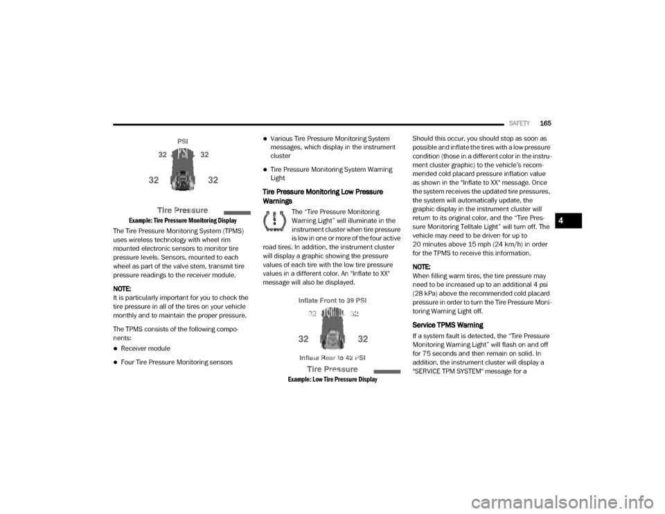
Example: Tire Pressure Monitoring Display
The Tire Pressure Monitoring System (TPMS)
uses wireless technology with wheel rim
mounted electronic sensors to monitor tire
pressure levels. Sensors, mounted to each
wheel as part of the valve stem, transmit tire
pressure readings to the receiver module.
NOTE:
It is particularly important for you to check the
tire pressure in all of the tires on your vehicle
monthly and to maintain the proper pressure.
The TPMS consists of the following compo -
nents:
Receiver module
Four Tire Pressure Monitoring sensors
Various Tire Pressure Monitoring System
messages, which display in the instrument
cluster
Tire Pressure Monitoring System Warning
Light
Tire Pressure Monitoring Low Pressure
Warnings
The “Tire Pressure Monitoring
Warning Light” will illuminate in the
instrument cluster when tire pressure
is low in one or more of the four active
road tires. In addition, the instrument cluster
will display a graphic showing the pressure
values of each tire with the low tire pressure
values in a different color. An "Inflate to XX"
message will also be displayed.
Example: Low Tire Pressure Display
Should this occur, you should stop as soon as
possible and inflate the tires with a low pressure
condition (those in a different color in the instru
-
ment cluster graphic) to the vehicle’s recom-
mended cold placard pressure inflation value
as shown in the "Inflate to XX" message. Once
the system receives the updated tire pressures,
the system will automatically update, the
graphic display in the instrument cluster will
return to its original color, and the “Tire Pres -
sure Monitoring Telltale Light” will turn off. The
vehicle may need to be driven for up to
20 minutes above 15 mph (24 km/h) in order
for the TPMS to receive this information.
NOTE:
When filling warm tires, the tire pressure may
need to be increased up to an additional 4 psi
(28 kPa) above the recommended cold placard
pressure in order to turn the Tire Pressure Moni -
toring Warning Light off.
Service TPMS Warning
If a system fault is detected, the “Tire Pressure
Monitoring Warning Light” will flash on and off
for 75 seconds and then remain on solid. In
addition, the instrument cluster will display a
"SERVICE TPM SYSTEM" message for a
4
20_DJD2_OM_EN_USC_t.book Page 165
Page 168 of 553
166SAFETY
minimum of five seconds and then display
dashes (- -) in place of the pressure value to indi -
cate which sensor is not being received.
If the ignition switch is cycled, this sequence will
repeat, providing the system fault still exists. If
the system fault no longer exists, the “Tire Pres -
sure Monitoring Warning Light” will no longer
flash, and the "SERVICE TPM SYSTEM" message
will no longer display, and a pressure value will
display in place of the dashes. A system fault
can occur due to any of the following:
Signal interference due to electronic devices
or driving next to facilities emitting the same
radio frequencies as the TPM sensors.
Installing aftermarket window tinting that
contains materials that may block radio wave
signals.
Accumulation of snow or ice around the
wheels or wheel housings.
Using tire chains on the vehicle.
Using wheels/tires not equipped with TPM
sensors.
A system fault may occur due to an incorrect
TPM sensor location condition. When a system
fault occurs due to an incorrect TPM sensor location, the “Tire Pressure Monitoring Warning
Light” will flash on and off for 75 seconds and
then remain on solid. The system fault will also
sound a chime. In addition, the instrument
cluster will display a “Tire Pressure Temporarily
Unavailable” message in place of the tire pres
-
sure display screen. If the ignition switch is
cycled, this sequence will repeat, providing the
system fault still exists. If the system fault no
longer exists, the “Tire Pressure Monitoring
Warning Light” will no longer flash and the tire
pressure display screen will be displayed
showing the tire pressure values the correct
locations.
Vehicles With Non Matching Full Size Spare Or
Compact Spare
The non matching full size spare or compact
spare tire does not have a TPM sensor.
Therefore, the TPMS will not monitor the
pressure in the non matching full size spare
or compact spare tire.
If you install the non matching full size spare
or compact spare tire in place of a road tire
that has a pressure below the low-pressure
warning limit, upon the next ignition switch
cycle, the TPM Warning Light and a “LOW
TIRE” message will remain on and a chime will sound. In addition, the graphic in the
instrument cluster will still display a pressure
value in a different color and an “Inflate to
XX” message.
After driving the vehicle for up to 20 minutes
above 15 mph (24 km/h), the TPM Warning
Light will flash on and off for 75 seconds and
then remain on solid. In addition, the instru -
ment cluster will display a "SERVICE TPM
SYSTEM" message for a minimum of five
seconds and then display dashes (- -) in place
of the pressure value.
For each subsequent ignition switch cycle, a
chime will sound, the TPM Warning Light will
flash on and off for 75 seconds and then
remain on solid, and the instrument cluster
will display a "SERVICE TPM SYSTEM"
message for a minimum of five seconds and
then display dashes (- -) in place of the pres -
sure value.
Once you repair or replace the original road
tire and reinstall it on the vehicle in place of
the non matching full size spare or compact
spare, the TPMS will update automatically. In
addition, the TPM Warning Light will turn off
and the graphic in the instrument cluster will
display a new pressure value instead of
20_DJD2_OM_EN_USC_t.book Page 166