service Ram 2500 2020 Manual PDF
[x] Cancel search | Manufacturer: RAM, Model Year: 2020, Model line: 2500, Model: Ram 2500 2020Pages: 553, PDF Size: 21.99 MB
Page 344 of 553

342IN CASE OF EMERGENCY
(Continued)
NOTE:
Your vehicle may be transmitting data as
authorized by the subscriber.
Never place anything on or near the vehicle’s
LTE (voice/data) or 4G (data) and GPS
antennas. You could prevent LTE (voice/
data) or 4G (data) and GPS signal reception,
which can prevent your vehicle from placing
an emergency call. An operable LTE (voice/
data) or 4G (data) network connection and a
GPS signal is required for the SOS Call
system to function properly.
General Information
The following regulatory statement applies to all
Radio Frequency (RF) devices equipped in this
vehicle:
This device complies with Part 15 of the FCC
Rules and with Innovation, Science and
Economic Development Canada license-exempt
RSS standard(s). Operation is subject to the
following two conditions:
1. This device may not cause harmful interfer
-
ence, and
2. This device must accept any interference received, including interference that may
cause undesired operation.
Le présent appareil est conforme aux CNR
d`Innovation, Science and Economic Develop -
ment applicables aux appareils radio exempts
de licence. L'exploitation est autorisée aux deux
conditions suivantes:
1. l'appareil ne doit pas produire de brouil -
lage, et
2. l'utilisateur de l'appareil doit accepter tout brouillage radioélectrique subi, même si le
brouillage est susceptible d'en comprom -
ettre le fonctionnement.
La operación de este equipo está sujeta a las
siguientes dos condiciones:
1. es posible que este equipo o dispositivo no cause interferencia perjudicial y
2. este equipo o dispositivo debe aceptar cual -
quier interferencia, incluyendo la que
pueda causar su operación no deseada. NOTE:
Changes or modifications not expressly
approved by the party responsible for compli
-
ance could void the user’s authority to operate
the equipment.
JACKING AND TIRE CHANGING
WARNING!
Do not attempt to change a tire on the side
of the vehicle close to moving traffic. Pull
far enough off the road to avoid the danger
of being hit when operating the jack or
changing the wheel.
Being under a jacked-up vehicle is
dangerous. The vehicle could slip off the
jack and fall on you. You could be crushed.
Never put any part of your body under a
vehicle that is on a jack. If you need to get
under a raised vehicle, take it to a service
center where it can be raised on a lift.
Never start or run the engine while the
vehicle is on a jack.
20_DJD2_OM_EN_USC_t.book Page 342
Page 345 of 553
IN CASE OF EMERGENCY343
NOTE:
If your vehicle is equipped with an air suspen -
sion system, there is a feature which allows the
automatic leveling to be disabled to assist with
changing a tire.
This feature can be activated through the Ucon -
nect system.
Refer to “Uconnect Settings” in “Multimedia”
for further information.
Jack Location
The jack and jack tools are stored under the
front passenger seat.
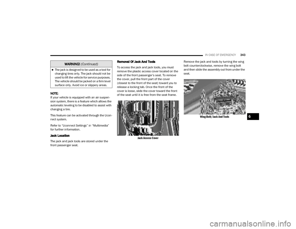
Removal Of Jack And Tools
To access the jack and jack tools, you must
remove the plastic access cover located on the
side of the front passenger’s seat. To remove
the cover, pull the front part of the cover
(closest to the front of the seat) toward you to
release a locking tab. Once the front of the
cover is loose, slide the cover toward the front
of the seat until it is free from the seat frame.
Jack Access Cover
Remove the jack and tools by turning the wing
bolt counterclockwise, remove the wing bolt
and then slide the assembly out from under the
seat.
Wing Bolt/Jack And Tools
The jack is designed to be used as a tool for
changing tires only. The jack should not be
used to lift the vehicle for service purposes.
The vehicle should be jacked on a firm level
surface only. Avoid ice or slippery areas.
WARNING! (Continued)
6
20_DJD2_OM_EN_USC_t.book Page 343
Page 349 of 553
IN CASE OF EMERGENCY347
(Continued)
Jacking Instructions
Jack Warning Label Lug Wrench Adapter Shown In Jack And Tools Assembly
1. Remove the spare wheel, jack, and tools
from storage.
2. Using the lug wrench, loosen, but do not remove, the wheel nuts by turning them
counterclockwise one turn while the wheel
is still on the ground. Changing a dually tire
requires the lug wrench adapter.
WARNING!
Carefully follow these tire changing warnings
to help prevent personal injury or damage to
your vehicle:
Always park on a firm, level surface as far
from the edge of the roadway as possible
before raising the vehicle.
Turn on the Hazard Warning Flashers.
Apply the parking brake firmly and set the
transmission in PARK.
Block the wheel diagonally opposite the
wheel to be raised.
Never start or run the engine with the
vehicle on a jack.
Do not let anyone sit in the vehicle when it
is on a jack.
Do not get under the vehicle when it is on a
jack. If you need to get under a raised
vehicle, take it to a service center where it
can be raised on a lift.
Only use the jack in the positions indicated
and for lifting this vehicle during a tire
change.
If working on or near a roadway, be
extremely careful of motor traffic.
To assure that spare tires, flat or inflated,
are securely stowed, spares must be
stowed with the valve stem facing the
ground.
WARNING! (Continued)
CAUTION!
Do not attempt to raise the vehicle by jacking
on locations other than those indicated in the
Jacking Instructions for this vehicle.
6
20_DJD2_OM_EN_USC_t.book Page 347
Page 352 of 553

350IN CASE OF EMERGENCY
Dual Rear Wheel Jack Placement
6. Finish tightening the lug nuts. Push down on the lug wrench while at the end of the handle
for increased leverage. Tighten the lug nuts in
a star pattern until each nut has been tight -
ened twice. For the correct lug nut torque refer
to “Wheel And Tire Torque Specifications” in
“Technical Specifications”. If in doubt about
the correct tightness, have them checked with
a torque wrench by an authorized dealer or
service station. 7. Install the wheel center cap and remove the
wheel blocks. Do not install chrome or
aluminum wheel center caps on the spare
wheel. This may result in cap damage.
8. Lower the jack to its fully closed position. Stow the replaced tire, jack, and tools as
previously described.
NOTE:
The bottle jack will not lower by turning the dial
(thumbwheel) by hand, it may be necessary to
use the jack driver in order to lower the jack.
9. Adjust the tire pressure when possible.
NOTE:
Do not oil wheel studs. For chrome wheels, do
not substitute with chrome plated lug nuts.
To Stow The Flat Or Spare
NOTE:
Have the flat tire repaired or replaced immedi -
ately.
1. Turn the wheel so that the valve stem is facing the ground and toward the rear of
the vehicle for convenience in checking the
spare tire inflation. Slide the wheel retainer
through the center of the wheel.
Reinstalling The Retainer
WARNING!
A loose tire or jack thrown forward in a
collision or hard stop, could endanger the
occupants of the vehicle. Always stow the jack
parts and the spare tire in the places
provided.
WARNING!
A loose tire or jack thrown forward in a
collision or hard stop could endanger the
occupants of the vehicle. Always stow the jack
parts and the spare tire in the places
provided. Have the deflated (flat) tire repaired
or replaced immediately.
20_DJD2_OM_EN_USC_t.book Page 350
Page 355 of 553
IN CASE OF EMERGENCY353
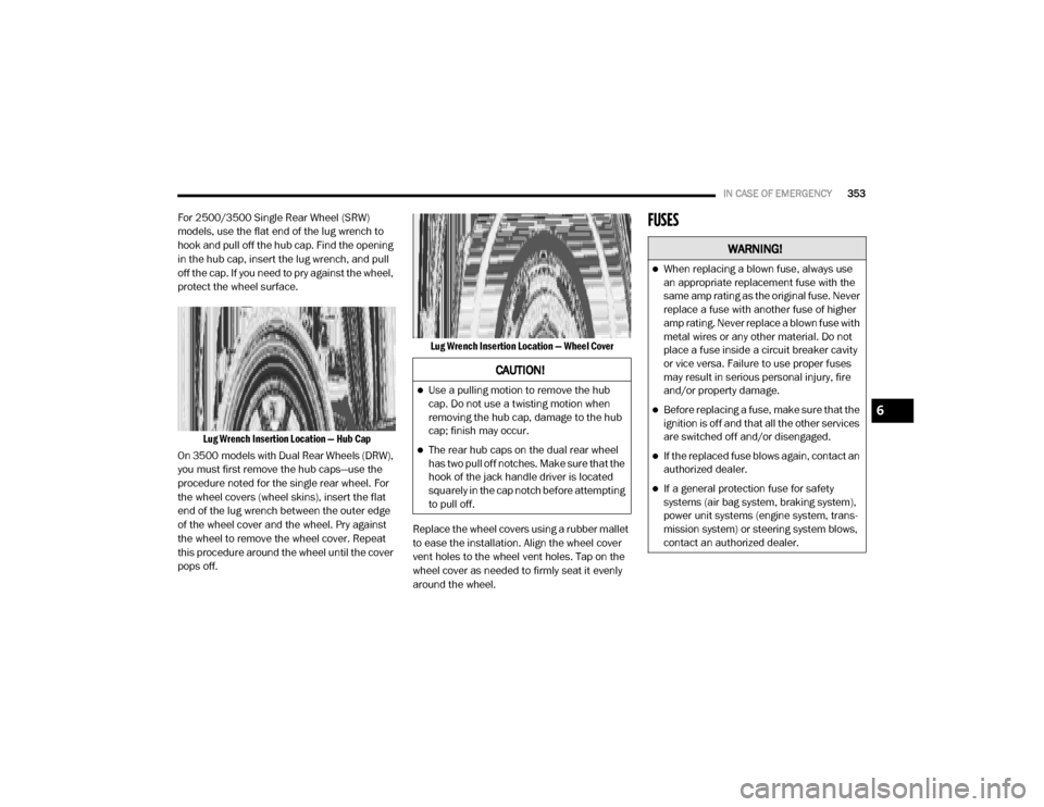
For 2500/3500 Single Rear Wheel (SRW)
models, use the flat end of the lug wrench to
hook and pull off the hub cap. Find the opening
in the hub cap, insert the lug wrench, and pull
off the cap. If you need to pry against the wheel,
protect the wheel surface.
Lug Wrench Insertion Location — Hub Cap
On 3500 models with Dual Rear Wheels (DRW),
you must first remove the hub caps—use the
procedure noted for the single rear wheel. For
the wheel covers (wheel skins), insert the flat
end of the lug wrench between the outer edge
of the wheel cover and the wheel. Pry against
the wheel to remove the wheel cover. Repeat
this procedure around the wheel until the cover
pops off.
Lug Wrench Insertion Location — Wheel Cover
Replace the wheel covers using a rubber mallet
to ease the installation. Align the wheel cover
vent holes to the wheel vent holes. Tap on the
wheel cover as needed to firmly seat it evenly
around the wheel.FUSES
CAUTION!
Use a pulling motion to remove the hub
cap. Do not use a twisting motion when
removing the hub cap, damage to the hub
cap; finish may occur.
The rear hub caps on the dual rear wheel
has two pull off notches. Make sure that the
hook of the jack handle driver is located
squarely in the cap notch before attempting
to pull off.
WARNING!
When replacing a blown fuse, always use
an appropriate replacement fuse with the
same amp rating as the original fuse. Never
replace a fuse with another fuse of higher
amp rating. Never replace a blown fuse with
metal wires or any other material. Do not
place a fuse inside a circuit breaker cavity
or vice versa. Failure to use proper fuses
may result in serious personal injury, fire
and/or property damage.
Before replacing a fuse, make sure that the
ignition is off and that all the other services
are switched off and/or disengaged.
If the replaced fuse blows again, contact an
authorized dealer.
If a general protection fuse for safety
systems (air bag system, braking system),
power unit systems (engine system, trans -
mission system) or steering system blows,
contact an authorized dealer.
6
20_DJD2_OM_EN_USC_t.book Page 353
Page 356 of 553
354IN CASE OF EMERGENCY
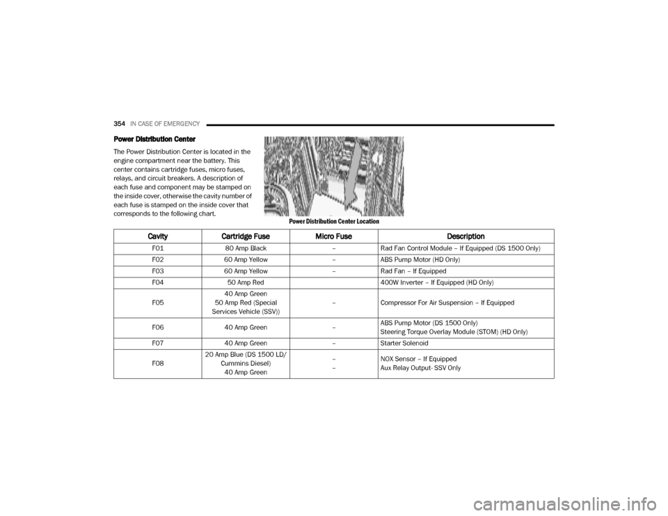
Power Distribution Center
The Power Distribution Center is located in the
engine compartment near the battery. This
center contains cartridge fuses, micro fuses,
relays, and circuit breakers. A description of
each fuse and component may be stamped on
the inside cover, otherwise the cavity number of
each fuse is stamped on the inside cover that
corresponds to the following chart.
Power Distribution Center Location
CavityCartridge Fuse Micro Fuse Description
F0180 Amp Black –Rad Fan Control Module – If Equipped (DS 1500 Only)
F02 60 Amp Yellow –ABS Pump Motor (HD Only)
F03 60 Amp Yellow –Rad Fan – If Equipped
F04 50 Amp Red 400W Inverter – If Equipped (HD Only)
F05 40 Amp Green
50 Amp Red (Special
Services Vehicle (SSV)) –
Compressor For Air Suspension – If Equipped
F06 40 Amp Green –ABS Pump Motor (DS 1500 Only)
Steering Torque Overlay Module (STOM) (HD Only)
F07 40 Amp Green –Starter Solenoid
F08 20 Amp Blue (DS 1500 LD/
Cummins Diesel)40 Amp Green –
–
NOX Sensor – If Equipped
Aux Relay Output- SSV Only
20_DJD2_OM_EN_USC_t.book Page 354
Page 358 of 553

356IN CASE OF EMERGENCY
F2225 Amp White (Cummins
Diesel) –
PCM – If Equipped
F23 30 Amp Pink –CBC Feed # 1
F24 30 Amp Pink –Driver Door Module
F25 30 Amp Pink –Front Wiper
F26 30 Amp Pink –Antilock Brakes / Stability Control Module / Valves – If
Equipped (DS 1500 Only)
F28 20 Amp Blue –Trailer Tow Backup Lights – If Equipped
F29 20 Amp Blue –Trailer Tow Parking Lights – If Equipped
F30 30 Amp Pink –Trailer Tow Receptacle / Trailer Tow (Separate E-Brake)/
Trailer Tow (BUX)
F31 30 Amp Pink –Diesel Heater Control – If Equipped (DS 1500 LD Diesel)
F31 20 Amp Blue –Aux App SSV Only - If Equipped
F32 ––Aux Feed, Special Services Vehicle-If Equipped (DS 1500
Only)
F33 20 Amp Blue –Trans Control Module – If Equipped (HD Only)
Aux Feed, SSV Only (DS 1500 Only)
F34 30 Amp Pink –Vehicle System Interface Module #2 – If Equipped (HD
Only)
SSV (DS 1500 Only)
F35 30 Amp Pink –Sunroof – If Equipped
F36 30 Amp Pink –Electric Back Light – If Equipped
Cavity Cartridge Fuse Micro Fuse Description
20_DJD2_OM_EN_USC_t.book Page 356
Page 369 of 553
IN CASE OF EMERGENCY367
To Reset The Manual Park Release:
1. Push the locking tab to the right, to unlock
the lever.
2. Rotate the Manual Park Release lever forward to its original position, until the
locking tab snaps into place to secure the
lever.
3. Pull gently on the tether strap to confirm that the lever is locked in its stowed posi-
tion.
4. Re-install the access cover.
IF YOUR ENGINE OVERHEATS
In any of the following situations, you can
reduce the potential for overheating by taking
the appropriate action.
On the highways — slow down.
In city traffic — while stopped, place the trans -
mission in NEUTRAL, but do not increase the
engine idle speed while preventing vehicle
motion with the brakes. NOTE:
There are steps that you can take to slow down
an impending overheat condition:
If your Air Conditioner (A/C) is on, turn it off.
The A/C system adds heat to the engine
cooling system and turning the A/C off can
help remove this heat.
You can also turn the temperature control to
maximum heat, the mode control to floor and
the blower control to high. This allows the
heater core to act as a supplement to the
radiator and aids in removing heat from the
engine cooling system.
FREEING A STUCK VEHICLE
If your vehicle becomes stuck in mud, sand, or
snow, it can often be moved using a rocking
motion. Turn the steering wheel right and left to
clear the area around the front wheels. Then
shift back and forth between DRIVE (D) and
REVERSE (R), while gently pressing the acceler
-
ator. Use the least amount of accelerator pedal
pressure that will maintain the rocking motion,
without spinning the wheels or racing the
engine.
WARNING!
You or others can be badly burned by hot
engine coolant (antifreeze) or steam from
your radiator. If you see or hear steam coming
from under the hood, do not open the hood
until the radiator has had time to cool. Never
try to open a cooling system pressure cap
when the radiator or coolant bottle is hot.
CAUTION!
Driving with a hot cooling system could
damage your vehicle. If the temperature
gauge reads HOT (H), pull over and stop the
vehicle. Idle the vehicle with the air
conditioner turned off until the pointer drops
back into the normal range. If the pointer
remains on HOT (H), and you hear continuous
chimes, turn the engine off immediately and
call for service.
6
20_DJD2_OM_EN_USC_t.book Page 367
Page 371 of 553

IN CASE OF EMERGENCY369
TOWING A DISABLED VEHICLE
This section describes procedures for towing a
disabled vehicle using a commercial towing
service.
If the transmission and drivetrain are operable,
disabled vehicles may also be towed as
described under “Recreational Towing” in the
“Starting And Operating” section. NOTE:
Vehicles equipped with the Air Suspension
System must be placed in Transport mode,
before tying them down (from the body) on a
trailer or flatbed truck. If the vehicle cannot be
placed in Transport mode (for example, engine
will not run), tie-downs must be fastened to the
axles (not to the body). Failure to follow these
instructions may cause fault codes to be set
and/or cause loss of proper tie-down tension.
Refer to “Air Suspension System — If Equipped”
in “Starting And Operating” for more informa
-
tion.
Proper towing or lifting equipment is required to
prevent damage to your vehicle. Use only tow
bars and other equipment designed for this
purpose, following equipment manufacturer’s
instructions. Use of safety chains is mandatory. Attach a tow bar or other towing device to main
structural members of the vehicle, not to
bumpers or associated brackets. State and
local laws regarding vehicles under tow must be
observed.If you must use the accessories (wipers,
defrosters, etc.) while being towed, the ignition
must be in the ON/RUN mode, not the ACC
mode.
Towing Condition
Wheels OFF The
Ground 2WD Models
4WD Models
Flat Tow NONE If transmission is operable:
• Transmission in NEUTRAL
• 30 mph (48 km/h) max speed
• 15 miles (24 km) max distance (6–speed
transmission)
• 30 miles (48 km) max distance (8–speed
transmission) See instructions in “Recreational Towing” under
“Starting And Operating”
Automatic Transmission in
PARK
Transfer Case in NEUTRAL (N)
Tow in forward direction
Wheel Lift Or Dolly Tow Front
NOT ALLOWED
Rear OK NOT ALLOWED
Flatbed ALL BEST METHOD BEST METHOD
6
20_DJD2_OM_EN_USC_t.book Page 369
Page 374 of 553

372IN CASE OF EMERGENCY
BULB REPLACEMENT
Replacement Bulbs
All of the inside bulbs are brass or glass-wedge base. Aluminum base bulbs are not approved.
Interior Bulbs
Bulb Name Bulb Number
Overhead Console Lamps TS 212–9
Dome Lamp 7679
For lighted switches, see an authorized dealer for replacement instructions.
Exterior Bulbs
Bulb Name Bulb Number
Low Beam (Halogen Reflector Headlamp) H11LL
High Beam (Halogen Reflector Headlamp) 9005LL
Low & High Beam (LED Reflector Headlamp) LED (Serviced At An Authorized Dealer)
Low & High Beam (LED Projector Headlamp) LED (Serviced At An Authorized Dealer)
Turn Signal / Front Position (Halogen Reflector Headlamp) 7444NA
Turn Signal / Front Position (LED Headlamps) LED (Serviced At An Authorized Dealer)
Front Side Marker (Halogen Reflector Headlamp) W5W
Front Side Marker (LED Headlamps) LED (Serviced At An Authorized Dealer)
Front Fog Lamps (Halogen Reflector Headlamp) H11LL
Front Fog Lamps (LED Headlamps) LED (Serviced At An Authorized Dealer)
20_DJD2_OM_EN_USC_t.book Page 372