instrument panel Ram 2500 2020 Manual PDF
[x] Cancel search | Manufacturer: RAM, Model Year: 2020, Model line: 2500, Model: Ram 2500 2020Pages: 553, PDF Size: 21.99 MB
Page 235 of 553

STARTING AND OPERATING233
Eight-Speed Automatic Transmission — If
Equipped
The transmission is controlled using a rotary
electronic gear selector located on the instru -
ment panel. The transmission gear range
(PRND) is displayed both above the gear
selector and in the instrument cluster. To select
a gear range, simply rotate the gear selector.
You must press the brake pedal to shift the
transmission out of PARK (or NEUTRAL, when
the vehicle is stopped or moving at low speeds).
To shift past multiple gear ranges at once (such
as PARK to DRIVE), simply rotate the gear
selector to the appropriate detent. Select the
DRIVE range for normal driving.
NOTE:
In the event of a mismatch between the gear
selector position and the actual transmission
gear (for example, driver selects PARK while
driving), the position indicator will blink continu -
ously until the selector is returned to the proper
position, or the requested shift can be
completed.
The electronically-controlled transmission
adapts its shift schedule based on driver inputs,
along with environmental and road conditions.
The transmission electronics are self-cali -brating; therefore, the first few shifts on a new
vehicle may be somewhat abrupt. This is a
normal condition, and precision shifts will
develop within a few hundred miles (kilome
-
ters).
Only shift from DRIVE to PARK or REVERSE
when the accelerator pedal is released and the
vehicle is stopped. Be sure to keep your foot on
the brake pedal when shifting between these
gears.
The transmission gear selector has only PARK,
REVERSE, NEUTRAL, and DRIVE positions.
Manual downshifts can be made using the Elec -
tronic Range Select (ERS) shift control. Pressing
the GEAR -/GEAR + switches (on the steering
wheel) while in the DRIVE position will select the
highest available transmission gear, and will
display that gear limit in the instrument cluster
as 1, 2, 3, etc. Refer to “Electronic Range Select
(ERS) Operation” in this section for further infor -
mation. Some models will display both the
selected gear limit, and the actual current gear,
while in ERS mode.
Electronic Transmission Gear Selector
Gear Ranges
Do not depress the accelerator pedal when
shifting from PARK or NEUTRAL into another
gear range.
NOTE:
After selecting any gear range, wait a moment
to allow the selected gear to engage before
accelerating. This is especially important when
the engine is cold.
PARK (P)
This range supplements the parking brake by
locking the transmission. The engine can be
started in this range. Never attempt to use
PARK while the vehicle is in motion. Apply the
parking brake when exiting the vehicle in this
range.5
20_DJD2_OM_EN_USC_t.book Page 233
Page 245 of 553
STARTING AND OPERATING243
Torque Converter Clutch
A feature designed to improve fuel economy
has been included in the automatic transmis -
sion on your vehicle. A clutch within the torque
converter engages automatically at calibrated
speeds. This may result in a slightly different
feeling or response during normal operation in
the upper gears. When the vehicle speed drops
or during some accelerations, the clutch auto -
matically disengages.
NOTE:
The torque converter clutch will not engage,
until the transmission fluid and engine
coolant are warm [usually after 1 to 3 miles
(2 to 5 km) of driving]. Because engine speed
is higher when the torque converter clutch is
not engaged, it may seem as if the transmis -
sion is not shifting properly when cold. This is normal. Using the Electronic Range Select
(ERS) shift control, when the transmission is
sufficiently warm, will demonstrate that the
transmission is able to shift into and out of
Overdrive.
If the vehicle has not been driven for several
days, the first few seconds of operation after
shifting the transmission into gear may seem
sluggish. This is due to the fluid partially
draining from the torque converter into the
transmission. This condition is normal and
will not cause damage to the transmission.
The torque converter will refill within five
seconds after starting the engine.
AUXILIARY SWITCHES — IF EQUIPPED
There can be up to six auxiliary switches located
in the lower switch bank of the instrument panel
which can be used to power various electronic
devices and PTO (Power Take Off) – If Equipped.
If Power Take Off is equipped, it will take the
place of the sixth Auxiliary switch. Connections
to the switches are found under the hood in the
connectors attached to the auxiliary Power
Distribution Center.
You have the ability to configure the function
-
ality of the auxiliary switches via the instrument cluster display. All switches can now be config
-
ured for setting the switch type operation to
latching or momentary, power source of either
battery or ignition, and ability to hold last state
across key cycles.
NOTE:
Holding last state conditions are met when
switch type is set to latching and power source
is set to ignition.
For further information on using the auxiliary
switches, please refer to the Ram Body Builders
Guide by accessing www.rambodybuilder.com
and choosing the appropriate links.
ACTIVE NOISE CANCELLATION
Your vehicle is equipped with an Active Noise
Cancellation system that cannot be turned off.
This system is designed to address exhaust and
engine noise. The system relies on four micro -
phones embedded in the headliner, which
monitor exhaust and engine noise, and assists
an onboard frequency generator, which creates
counteracting sound waves in the audio
system’s speakers. This helps keep the vehicle
quiet at idle and during drive. The system is
deactivated when the windows are rolled down.
WARNING!
Do not use the “TOW/HAUL” feature when
driving in icy or slippery conditions. The
increased engine braking can cause the rear
wheels to slide, and the vehicle to swing
around with the possible loss of vehicle
control, which may cause an accident
possibly resulting in personal injury or death.
5
20_DJD2_OM_EN_USC_t.book Page 243
Page 253 of 553
STARTING AND OPERATING251
Air Suspension Modes
The air suspension system has multiple modes
to protect the system in unique situations:
Tire/Jack Mode
To assist with changing a tire, the air suspen -
sion system has a feature which allows the
automatic leveling to be disabled. This mode is
intended to be enabled with the engine running.
Refer to “Instrument Cluster Display” in
“Getting To Know Your Instrument Panel” or
“Uconnect Settings” in “Multimedia” (if
equipped with a touch screen radio) for further
information.
NOTE:
This mode is intended to be enabled with the
engine running.
Transport Mode
For towing your vehicle with four wheels off the
road, the air suspension system has a feature
which will put the vehicle below Normal Ride
Height (NRH) and disable the automatic load
leveling system. This mode is intended to be
enabled with engine running. Refer to “Instru -
ment Cluster Display” in “Getting To Know Your
Instrument Panel” or “Uconnect Settings” in
“Understanding Your Instrument Panel” if equipped with a touch screen radio for further
information.
NOTE:
This mode is intended to be enabled with the
engine running.
Wheel Alignment Mode
Before performing a wheel alignment this mode
must be enabled. Refer to “Instrument Cluster
Display” in “Getting To Know Your Instrument
Panel” or “Uconnect Settings” in “Multimedia”
(if equipped with a touch screen radio) for
further information.
NOTE:
This mode is intended to be enabled with the
engine running.
Bed Lowering Mode
This setting is used to lower the rear suspension
to the lowest possible height and disable the air
suspension system. It enables easier loading/
unloading of the truck and makes it easier to
hook up trailers. Refer to “Instrument Cluster
Display” in “Getting To Know Your Instrument
Panel” or “Uconnect Settings” in “Under
-
standing Your Instrument Panel” if equipped with a touch screen radio for further informa
-
tion.
Protection Strategy
In order to “protect” the air suspension system,
the vehicle will disable load leveling as required
(suspension overloaded, battery charge low,
etc.). Load leveling will automatically resume as
soon as system operation requirements are
met. See your authorized dealer if system does
not resume.
Instrument Cluster Display Messages
When the appropriate conditions exist, a
message will appear in the instrument cluster
display. Refer to “Instrument Cluster Display” in
“Getting To Know Your Instrument Panel” for
further information.
An audible chime will be heard whenever a
system error has been detected.
See your authorized dealer for system service if
normal operation does not resume.
Operation
Pushing the Alternate Trailer Height (ATH)
button once while at Normal Ride Height (NRH),
will lower the vehicle to Alternate Trailer Height
(ATH) and will illuminate the LED.
5
20_DJD2_OM_EN_USC_t.book Page 251
Page 256 of 553

254STARTING AND OPERATING
advantage to increasing ride height is the posi -
tive effect it has on approach/departure and
break over angles.
This system is controlled by the electronic
control sway bar switch located below the
instrument panel.
Sway Bar Disconnect Button
Push the SWAY BAR switch to activate the
system. Push the switch again to deactivate the
system. The “Sway Bar Indicator Light” (located
in the instrument cluster) will illuminate when
the bar is disconnected. The “Sway Bar Indi -
cator Light” will flash during activation transi -
tion, or when activation conditions are not met.
The stabilizer/sway bar should remain in
on-road mode during normal driving conditions. To disconnect the stabilizer/sway bar, shift to
either 4WD HIGH or 4WD LOW and push the
SWAY BAR button to obtain the Off-Road posi
-
tion. Refer to “Four Wheel Drive Operation” in
“Starting And Operating” for further informa -
tion. The “Sway Bar Indicator Light” will flash
until the stabilizer/sway bar has been fully
disconnected. NOTE:
The stabilizer/sway bar may be torque locked
due to left and right suspension height differ
-
ences. This condition is due to driving surface
differences or vehicle loading. In order for the
stabilizer/sway bar to disconnect/reconnect,
the right and left halves of the bar must be
aligned. This alignment may require that the
vehicle be driven onto level ground or rocked
from side to side.
To return to the On-Road mode, push the SWAY
BAR button again.WARNING!
Do not disconnect the stabilizer bar and drive
on hard surfaced roads or at speeds above
18 mph (29 km/h), you may lose control of
the vehicle, which could result in serious
injury or death. The front stabilizer bar
enhances vehicle stability and assists in
maintaining control of the vehicle. The system
monitors vehicle speed and will attempt to
reconnect the stabilizer bar at speeds over
18 mph (29 km/h). This is indicated by a
flashing off road light and solid on road light.
Once vehicle speed is reduced below 14 mph
(22 km/h), the system will attempt to return
to the Off-Road mode.
WARNING!
If the stabilizer/sway bar will not return to
On-Road mode, vehicle stability is reduced.
Do not attempt to drive the vehicle over
18 mph (29 km/h). Driving faster than
18 mph (29 km/h) may cause loss of control
of the vehicle, which could result in serious
injury or death. Contact your local service
center for assistance.
20_DJD2_OM_EN_USC_t.book Page 254
Page 276 of 553

274STARTING AND OPERATING
To Activate
Push the on/off button to activate the Speed
Control. The cruise indicator light in the instru -
ment cluster display will illuminate. To turn the
system off, push the on/off button a second
time. The cruise indicator light will turn off. The
system should be turned off when not in use.
To Set A Desired Speed
Turn the Speed Control on. When the vehicle
has reached the desired speed, push the SET (-)
button and release. Release the accelerator
and the vehicle will operate at the selected
speed.
NOTE:
The vehicle should be traveling at a steady
speed and on level ground before pushing the
SET (-) button.
To Vary The Speed Setting
To Increase Speed
When the Speed Control is set, you can increase
speed by pushing the RES (+) button.
The driver’s preferred units can be selected
through the instrument panel settings (if
equipped). Refer to “Getting To Know Your
Instrument Panel” for more information. The
speed increment shown is dependent on the
chosen speed unit of U.S. (mph) or Metric
(km/h):
U.S. Speed (mph)
Pushing the RES (+) button once will result in
a 1 mph increase in set speed. Each subse -
quent tap of the button results in an increase
of 1 mph.
If the button is continually pushed, the set
speed will continue to increase until the
button is released, then the new set speed
will be established.
Metric Speed (km/h)
Pushing the RES (+) button once will result in
a 1 km/h increase in set speed. Each subse -
quent tap of the button results in an increase
of 1 km/h.
If the button is continually pushed, the set
speed will continue to increase until the
button is released, then the new set speed
will be established.
To Decrease Speed
When the Speed Control is set, you can
decrease speed by pushing the SET (-) button.
The driver’s preferred units can be selected
through the instrument panel settings (if
equipped). Refer to “Getting To Know Your
Instrument Panel” for more information. The
speed decrement shown is dependent on the
chosen speed unit of U.S. (mph) or Metric
(km/h):
U.S. Speed (mph)
Pushing the SET (-) button once will result in
a 1 mph decrease in set speed. Each subse -
quent tap of the button results in a decrease
of 1 mph.
If the button is continually pushed, the set
speed will continue to decrease until the
button is released, then the new set speed
will be established.
WARNING!
Leaving the Speed Control system on when
not in use is dangerous. You could
accidentally set the system or cause it to go
faster than you want. You could lose control
and have an accident. Always leave the
system off when you are not using it.
20_DJD2_OM_EN_USC_t.book Page 274
Page 290 of 553

288STARTING AND OPERATING
To Set A Desired Speed
Turn the Normal (Fixed Speed) Cruise
Control on. When the vehicle has
reached the desired speed, push the
RES (+) or SET (-) button and release.
Release the accelerator and the vehicle will
operate at the selected speed. Once a speed
has been set a message “CRUISE CONTROL SET
TO MPH (km/h)” will appear indicating what
speed was set. This light will turn on when the
system is turned on via the on/off control. It
turns green when the cruise control is set.
To Vary The Speed Setting
To Increase Speed
When the Normal (Fixed Speed) Cruise Control
is set, you can increase speed by pushing the
RES (+) button.
The driver's preferred units can be selected
through the instrument panel settings. Refer to
“Instrument Cluster Display” in “Getting To
Know Your Instrument Panel” for more informa-
tion. The speed increment shown is dependent
on the speed of U.S. (mph) or Metric (km/h)
units:
U.S. Speed (mph)
Pushing the RES (+) button once will result in
a 1 mph increase in set speed. Each subse -
quent tap of the button results in an increase
of 1 mph.
If the button is continually pushed, the set
speed will continue to increase in 5 mph
increments until the button is released. The
increase in set speed is reflected in the
instrument cluster display. Metric Speed (km/h)
Pushing the RES (+) button once will result in
a 1 km/h increase in set speed. Each subse -
quent tap of the button results in an increase
of 1 km/h.
If the button is continually pushed, the set
speed will continue to increase in 10 km/h
increments until the button is released. The
increase in set speed is reflected in the
instrument cluster display.
To Decrease Speed
When the Normal (Fixed Speed) Cruise Control
is set, you can decrease speed by pushing the
SET (-) button.
The driver's preferred units can be selected
through the instrument panel settings. Refer to
“Instrument Cluster Display” in “Getting To
Know Your Instrument Panel” for more informa-
tion. The speed decrement shown is dependent
on the speed of U.S. (mph) or Metric (km/h)
units:
U.S. Speed (mph)
Pushing the SET (-) button once will result in
a 1 mph decrease in set speed. Each subse -
WARNING!
In the Normal (Fixed Speed) Cruise Control
mode, the system will not react to vehicles
ahead. In addition, the proximity warning
does not activate and no alarm will sound
even if you are too close to the vehicle ahead
since neither the presence of the vehicle
ahead nor the vehicle-to-vehicle distance is
detected. Be sure to maintain a safe distance
between your vehicle and the vehicle ahead.
Always be aware which mode is selected.
20_DJD2_OM_EN_USC_t.book Page 288
Page 292 of 553

290STARTING AND OPERATING
ParkSense Sensors
The four ParkSense sensors, located in the rear
fascia/bumper, monitor the area behind the
vehicle that is within the sensors’ field of view.
The sensors can detect obstacles from approxi -
mately 18 inches (45 cm) up to 79 inches (200
cm) from the rear fascia/bumper in the hori -
zontal direction, depending on the location, type
and orientation of the obstacle.
NOTE:
If equipped as a dually, the ParkSense system
has six rear sensors to assist in detection
around the dually flares.
ParkSense Warning Display
The ParkSense Warning screen is located within
the instrument cluster display. It provides visual
warnings to indicate the distance between the
rear fascia/bumper and the detected obstacle.
Refer to “Instrument Cluster Display” in
“Getting To Know Your Instrument Panel” for
further information.
ParkSense Display
When the vehicle is in REVERSE, the warning
display will turn on indicating the system status.
The system will indicate a detected obstacle by
showing a single arc in the left and/or right rear
regions based on the object’s distance and
location relative to the vehicle.
If an object is detected in the left and/or right
rear region, the display will show a single solid
arc in the left and/or right rear region and the
system will produce a tone. As the vehicle
moves closer to the object, the display will show
the single arc moving closer to the vehicle and
the tone will change from a single 1/2 second
tone to slow, to fast, to continuous.
Single 1/2 Second Tone Slow Tone
Slow Tone
20_DJD2_OM_EN_USC_t.book Page 290
Page 296 of 553
294STARTING AND OPERATING
PARKSENSE FRONT AND REAR PARK ASSIST
The ParkSense Park Assist system provides
visual and audible indications of the distance
between the rear, and/or front fascia/bumper,
and a detected obstacle when backing up or
moving forward (e.g. during a parking
maneuver).
Refer to “ParkSense System Usage Precau -
tions” in this section for limitations of this
system and recommendations.
ParkSense will retain the system state (enabled
or disabled) from the previous ignition cycle
when the ignition is placed in the ON/RUN posi -
tion. ParkSense can be active only when the gear
selector is in REVERSE or DRIVE. If ParkSense is
enabled at one of these gear selector positions,
the system will remain active until the vehicle
speed is increased to approximately 7 mph
(11 km/h) or above. A warning will appear in the
instrument cluster display when the vehicle is in
REVERSE, indicating the vehicle is above Park
-
Sense operating speed. The system will become
active again if the vehicle speed is decreased to
speeds less than approximately 6 mph (9 km/h).
ParkSense Sensors
The four ParkSense sensors, located in the rear
fascia/bumper, monitor the area behind the
vehicle that is within the sensors’ field of view.
The sensors can detect obstacles from approxi -
mately 18 inches (45 cm) up to 79 inches (200 cm) from the rear fascia/bumper in the
horizontal direction, depending on the location,
type and orientation of the obstacle.
NOTE:
If equipped as a dually, the ParkSense system
has six rear sensors to assist in detection
around the dually flares.
The six ParkSense sensors, located in the front
fascia/bumper, monitor the area in front of the vehicle that is within the sensors’ field of view.
The sensors can detect obstacles from approxi
-
mately 12 inches (30 cm) up to 47 inches (120 cm) from the front fascia/bumper in the
horizontal direction, depending on the location,
type and orientation of the obstacle.
ParkSense Warning Display
The ParkSense Warning screen is located within
the instrument cluster display. It provides visual
warnings to indicate the distance between the
rear fascia/bumper and/or front fascia/bumper
and the detected obstacle. Refer to “Instrument
Cluster Display” in “Getting To Know Your
Instrument Panel” for further information.
The vehicle must be driven slowly when
using ParkSense in order to be able to stop
in time when an obstacle is detected. It is
recommended that the driver looks over
his/her shoulder when using ParkSense.
CAUTION! (Continued)
20_DJD2_OM_EN_USC_t.book Page 294
Page 302 of 553
300STARTING AND OPERATING
Turning LaneSense On Or Off
The LaneSense button is located on
the switch panel below the Uconnect
display.
NOTE:
If your vehicle is equipped with a 12–inch Ucon -
nect Display screen, the LaneSense button is
located above the display.
To turn the LaneSense system on, push the
LaneSense button (LED turns off). A “Lane -
Sense On” message is shown in the instrument
cluster display.
Lane Sense On Message
To turn the LaneSense system off, push the
LaneSense button again (LED turns on).
NOTE:
The LaneSense system will retain the last
system state (on or off) from the last ignition
cycle when the ignition is placed in the ON/RUN
position.
LaneSense Warning Message
The LaneSense system will indicate the current
lane drift condition through the instrument
cluster display.
When the LaneSense system is on, the lane
lines are gray when both of the lane boundaries
have not been detected and the LaneSense tell
-
tale is solid white.
System ON (Gray Lines) With White Telltale
Left Lane Departure — Only Left Lane Detected
When the LaneSense system is on, the Lane-
Sense Telltale is solid white when only the
left lane marking has been detected and the
system is ready to provide visual warnings in
the instrument cluster display if an uninten -
tional lane departure occurs on the left side.
When the LaneSense system senses the lane
has been approached and is in a lane depar -
ture situation, the visual warning in the
instrument cluster display will show the left
lane line flashing yellow (on/off). The Lane -
Sense telltale changes from solid white to
flashing yellow.
20_DJD2_OM_EN_USC_t.book Page 300
Page 315 of 553
STARTING AND OPERATING313
NOTE:
When the fuel nozzle “clicks” or shuts off, the
fuel tank is full.
Tighten the gas cap until you hear a “clicking”
sound. This is an indication that the gas cap
is tightened properly. The MIL in the instru -
ment cluster may turn on if the gas cap is not
secured properly. Make sure that the gas cap
is tightened each time the vehicle is refueled.
Loose Fuel Filler Cap Message
If the vehicle diagnostic system deter -
mines that the fuel filler cap is loose,
improperly installed, or damaged, a
loose gASCAP indicator will display in
the instrument cluster telltale display area.
Refer to “Instrument Cluster Display” in
“Getting To Know Your Instrument Panel” for
further information. Tighten the fuel filler cap
properly and push the RIGHT button to turn off
the message. If the problem continues, the
message will appear the next time the vehicle is
started.
REFUELING THE VEHICLE — DIESEL ENGINE
1. Open the fuel filler door.
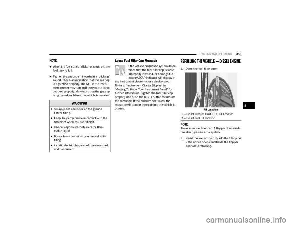
Fill Locations
NOTE:
There is no fuel filler cap. A flapper door inside
the filler pipe seals the system.
2. Insert the fuel nozzle fully into the filler pipe – the nozzle opens and holds the flapper
door while refueling.
WARNING!
Always place container on the ground
before filling.
Keep the pump nozzle in contact with the
container when you are filling it.
Use only approved containers for flam -
mable liquid.
Do not leave container unattended while
filling.
A static electric charge could cause a spark
and fire hazard.
1 — Diesel Exhaust Fluid (DEF) Fill Location
2 — Diesel Fuel Fill Location
5
20_DJD2_OM_EN_USC_t.book Page 313