check engine Ram 2500 2020 Owner's Manual
[x] Cancel search | Manufacturer: RAM, Model Year: 2020, Model line: 2500, Model: Ram 2500 2020Pages: 553, PDF Size: 21.99 MB
Page 6 of 553

4
SLIDE-IN CAMPERS .......................................... 100 Camper Applications .................................100
EASY-OFF TAILGATE ......................................... 100
Disconnecting The Rear Camera And
Remote Keyless Entry ...............................100 Removing The Tailgate .............................. 101
Locking Tailgate .........................................101
TRI-FOLD TONNEAU COVER — IF EQUIPPED .. 101
Tri-Fold Tonneau Cover Removal ..............102
Tri-Fold Tonneau Cover Installation ..........104
Tri-Fold Tonneau Cover Cleaning ..............107
GETTING TO KNOW YOUR INSTRUMENT PANEL
BASE / MIDLINE INSTRUMENT CLUSTER —
GAS ENGINE ....................................................... 108
Base / Midline Instrument Cluster
Descriptions — Gas Engine .......................109
PREMIUM INSTRUMENT CLUSTER —
GAS ENGINE ....................................................... 111
Premium Instrument Cluster Descriptions —
Gas Engine .................................................112
BASE INSTRUMENT CLUSTER — DIESEL
ENGINE ............................................................... 113
Base Instrument Cluster Descriptions —
Diesel Engine .............................................114
PREMIUM INSTRUMENT CLUSTER — DIESEL
ENGINE ................................................................ 116
Premium Instrument Cluster Descriptions —
Diesel Engine .............................................117 INSTRUMENT CLUSTER DISPLAY ................... 117
Instrument Cluster Display Controls......... 118
Oil Life Reset ............................................. 119
Display Menu Items ................................... 119
Diesel Messages And Warnings — 6.7L
Cummins Diesel Engine ............................ 124 Battery Saver On/Battery Saver Mode
Message — Electrical Load Reduction
Actions — If Equipped ................................ 128
WARNING LIGHTS AND MESSAGES ................130
Red Warning Lights ................................... 130
Yellow Warning Lights ............................... 133
Yellow Indicator Lights .............................. 137
Green Indicator Lights ............................... 140
White Indicator Lights ............................... 141
Blue Indicator Lights.................................. 141
ONBOARD DIAGNOSTIC SYSTEM — OBD II..... 141
Onboard Diagnostic System (OBD II)
Cybersecurity ............................................. 142
EMISSIONS INSPECTION AND MAINTENANCE
PROGRAMS......................................................... 142
SAFETY
SAFETY FEATURES .............................................144
Anti-Lock Brake System (ABS) ................. 144
Electronic Brake Control (EBC) System .... 145 AUXILIARY DRIVING SYSTEMS ........................ 153
Blind Spot Monitoring (BSM) —
If Equipped ................................................ 153 Forward Collision Warning (FCW) With
Mitigation — If Equipped ........................... 160 Tire Pressure Monitoring System
(TPMS) ........................................................ 163
OCCUPANT RESTRAINT SYSTEMS ................. 171
Occupant Restraint Systems Features ... 171
Important Safety Precautions ................... 171
Seat Belt Systems .................................... 172
Supplemental Restraint Systems (SRS)... 181
Child Restraints ......................................... 190
Transporting Pets ...................................... 208
SAFETY TIPS ....................................................... 208
Transporting Passengers .......................... 208
Exhaust Gas .............................................. 208
Safety Checks You Should Make Inside
The Vehicle ................................................ 209 Periodic Safety Checks You Should Make
Outside The Vehicle ................................... 210
20_DJD2_OM_EN_USC_t.book Page 4
Page 10 of 553

8
ENHANCED ACCIDENT RESPONSE SYSTEM
(EARS) ................................................................ 371
EVENT DATA RECORDER (EDR) ....................... 371
BULB REPLACEMENT ........................................ 372 Replacement Bulbs ...................................372
Replacing Exterior Bulbs ...........................374
SERVICING AND MAINTENANCE
SCHEDULED SERVICING — GAS ENGINE ....... 380Maintenance Plan — Gasoline Engine......380
Heavy Duty Use Of The Vehicle ................. 384
SCHEDULED SERVICING— DIESEL ENGINE .... 384
Oil Change Indicator System — Cummins
Diesel ..........................................................385 Perform Service Indicator — Cummins
Diesel ..........................................................385
Maintenance Plan — Cummins Diesel
Engine ........................................................ 386
ENGINE COMPARTMENT .................................. 391
6.4L Engine ...............................................391
6.7L Diesel Engine — Six-Speed 68RFE ..392
6.7L Diesel Engine — Six-Speed
AS69RC HD ................................................393 Checking Oil Level — Gas Engine .............394
Checking Oil Level — Diesel Engine ..........394
Adding Washer Fluid..................................394
Maintenance-Free Battery .......................395
Pressure Washing ......................................395 DEALER SERVICE ..............................................396
Engine Oil .................................................. 396
Engine Oil Filter .......................................... 398
Engine Air Cleaner Filter............................ 398
Air Conditioner Maintenance .................... 400
Accessory Drive Belt Inspection ............... 403
Draining Fuel/Water Separator Filter —
Diesel Engine ............................................ 403 Engine Mounted Fuel Filter Replacement —
Diesel Engine ............................................. 405 Underbody Mounted Fuel Filter
Replacement — Diesel Engine .................. 406 Priming If The Engine Has Run Out Of
Fuel — Diesel Engine ................................. 407 Intervention Regeneration Strategy —
Message Process Flow ............................. 407 Diesel Exhaust Fluid .................................. 408
Body Lubrication ........................................ 408
Windshield Wiper Blades .......................... 409
Exhaust System ........................................ 410
Cooling System ......................................... 411
Charge Air Cooler — Inter-Cooler .............. 415
Brake System ............................................ 415
Automatic Transmission............................ 416
Rear Axle And 4x4 Front Driving Axle Fluid
Level .......................................................... 418 Transfer Case ............................................ 419
Noise Control System Required
Maintenance & Warranty ......................... 419 HOISTING ........................................................... 422
TIRES ................................................................... 422
Tire Safety Information.............................. 422
Tires — General Information .................... 428
Tire Types ................................................... 432
Spare Tires — If Equipped ......................... 433
Wheel And Wheel Trim Care ..................... 434
Tire Chains And Traction Devices ............ 435
Tire Rotation Recommendations ............. 436
DEPARTMENT OF TRANSPORTATION UNIFORM
TIRE QUALITY GRADES .................................... 438
Treadwear .................................................. 438
Traction Grades ......................................... 438
Temperature Grades ................................. 438
STORING THE VEHICLE ..................................... 439
BODYWORK ........................................................ 439
Protection From Atmospheric Agents....... 439
Body And Underbody Maintenance .......... 439
Preserving The Bodywork.......................... 440
INTERIORS ......................................................... 442
Seats And Fabric Parts .............................. 442
Plastic And Coated Parts........................... 442
Leather Parts ............................................. 443
Glass Surfaces .......................................... 443
20_DJD2_OM_EN_USC_t.book Page 8
Page 26 of 553
24GETTING TO KNOW YOUR VEHICLE
(Continued)
Remote Start Comfort Systems — If
Equipped
When remote start is activated, the heated
steering wheel, and driver heated seat features
will automatically turn on in cold weather. In
warm weather, the driver vented seat feature
will automatically turn on when the remote start
is activated. These features will stay on through
the duration of remote start or until the ignition
switch is placed in the ON/RUN position.
NOTE:
The Remote Start Comfort system can be acti-
vated and deactivated through the Uconnect
System under “Auto-On Comfort And Remote
Start”. Refer to “Uconnect Settings” in “Multi -
media” for further information on Remote Start
Comfort System operation.
SENTRY KEY
The Sentry Key Immobilizer system prevents
unauthorized vehicle operation by disabling the
engine. The system does not need to be armed
or activated. Operation is automatic, regardless
of whether the vehicle is locked or unlocked.
The system uses a key fob, keyless push button
ignition and a Radio Frequency (RF) receiver to
prevent unauthorized vehicle operation. There -fore, only key fobs that are programmed to the
vehicle can be used to start and operate the
vehicle. The system cannot reprogram a key fob
obtained from another vehicle.
After placing the ignition switch in the ON/RUN
position, the vehicle security light will turn on for
three seconds for a bulb check. If the light
remains on after the bulb check, it indicates
that there is a problem with the electronics. In
addition, if the light begins to flash after the
bulb check, it indicates that someone
attempted to start the engine with an invalid key
fob. In the event that a valid key fob is used to
start the engine but there is an issue with the
vehicle electronics, the engine will start and
shut off after two seconds.
If the vehicle security light turns on during
normal vehicle operation (vehicle running for
longer than 10 seconds), it indicates that there
is a fault in the electronics. Should this occur,
have the vehicle serviced as soon as possible by
an authorized dealer.
All of the key fobs provided with your new
vehicle have been programmed to the vehicle
electronics.
Key Programming
Programming key fobs may be performed at an
authorized dealer.
Replacement Keys
NOTE:
Only key fobs that are programmed to the vehicle
electronics can be used to start and operate the
vehicle. Once a key fob is programmed to a vehicle,
it cannot be programmed to any other vehicle.
CAUTION!
The Sentry Key Immobilizer system is not
compatible with some aftermarket remote
starting systems. Use of these systems may
result in vehicle starting problems and loss of
security protection.
CAUTION!
Always remove the key fobs from the
vehicle and lock all doors when leaving the
vehicle unattended.
20_DJD2_OM_EN_USC_t.book Page 24
Page 131 of 553
GETTING TO KNOW YOUR INSTRUMENT PANEL129
NOTE:
The charging system is independent from
load reduction. The charging system
performs a diagnostic on the charging
system continuously.
If the Battery Charge Warning Light is on it
may indicate a problem with the charging
system. Refer to “Warning Lights And
Messages” in “Getting To Know Your Instru-
ment Panel” for further information.
The electrical loads that may be switched off (if
equipped), and vehicle functions which can be
affected by load reduction:
Heated Seats/Vented Seats/Heated Wheel
Rear Defroster And Heated Mirrors
HVAC System
115 Volts AC Power Inverter System
Audio and Telematics System Loss of the battery charge may indicate one or
more of the following conditions:
The charging system cannot deliver enough
electrical power to the vehicle system
because the electrical loads are larger than
the capability of charging system. The
charging system is still functioning properly.
Turning on all possible vehicle electrical
loads (e.g. HVAC to max settings, exterior and
interior lights, overloaded power outlets
+12 Volts, 115 Volts AC, USB ports) during
certain driving conditions (city driving,
towing, frequent stopping).
Installing options like additional lights,
upfitter electrical accessories, audio
systems, alarms and similar devices.
Unusual driving cycles (short trips separated
by long parking periods).
The vehicle was parked for an extended
period of time (weeks, months).
The battery was recently replaced and was
not charged completely.
The battery was discharged by an electrical
load left on when the vehicle was parked.
The battery was used for an extended period
with the engine not running to supply radio,
lights, chargers, +12 Volts portable appli
-
ances like vacuum cleaners, game consoles
and similar devices.
What to do when an electrical load reduction
action message is present (“Battery Saver On”
or “Battery Saver Mode”)
During a trip:
Reduce power to unnecessary loads if
possible:
Turn off redundant lights (interior or exte -
rior).
Check what may be plugged in to power outlets +12 Volts, 115 Volts AC, USB
ports.
Check HVAC settings (blower, tempera -
ture).
Check the audio settings (volume).
3
20_DJD2_OM_EN_USC_t.book Page 129
Page 133 of 553
GETTING TO KNOW YOUR INSTRUMENT PANEL131
the brake fluid level in the master cylinder has
dropped below a specified level.
The light will remain on until the cause is
corrected.
NOTE:
The light may flash momentarily during sharp
cornering maneuvers, which change fluid level
conditions. The vehicle should have service
performed, and the brake fluid level checked.
If brake failure is indicated, immediate repair is
necessary.
Vehicles equipped with the Anti-Lock Brake
System (ABS) are also equipped with Electronic
Brake Force Distribution (EBD). In the event of
an EBD failure, the Brake Warning Light will turn
on along with the ABS Light. Immediate repair to
the ABS system is required. Operation of the Brake Warning Light can be
checked by turning the ignition switch from the
OFF position to the ON/RUN position. The light
should illuminate for approximately two
seconds. The light should then turn off unless
the parking brake is applied or a brake fault is
detected. If the light does not illuminate, have
the light inspected by an authorized dealer.
The light also will turn on when the parking
brake is applied with the ignition switch in the
ON/RUN position.
NOTE:
This light shows only that the parking brake is
applied. It does not show the degree of brake
application.
Hood Open Warning Light
This warning light will illuminate when
the hood is ajar/open and not fully
closed.
NOTE:
If the vehicle is moving, there will also be a
single chime.
Vehicle Security Warning Light — If Equipped
This light will flash at a fast rate for
approximately 15 seconds when the
vehicle security alarm is arming, and
then will flash slowly until the vehicle
is disarmed.
Engine Coolant Temperature Warning Light
This warning light warns of an over -
heated engine condition. If the engine
coolant temperature is too high, this
indicator will illuminate and a single
chime will sound. If the temperature reaches
the upper limit, a continuous chime will sound
for four minutes or until the engine is able to
cool; whichever comes first.
If the light turns on while driving, safely pull over
and stop the vehicle. If the Air Conditioning
(A/C) system is on, turn it off. Also, shift the
transmission into NEUTRAL and idle the vehicle.
If the temperature reading does not return to
normal, turn the engine off immediately and call
for service.
Refer to “If Your Engine Overheats” in “In Case
Of Emergency” for further information.
WARNING!
Driving a vehicle with the red brake light on is
dangerous. Part of the brake system may
have failed. It will take longer to stop the
vehicle. You could have a collision. Have the
vehicle checked immediately.
3
20_DJD2_OM_EN_USC_t.book Page 131
Page 134 of 553
132GETTING TO KNOW YOUR INSTRUMENT PANEL
Battery Charge Warning Light
This warning light will illuminate when
the battery is not charging properly. If
it stays on while the engine is running,
there may be a malfunction with the
charging system. Contact an authorized dealer
as soon as possible.
This indicates a possible problem with the elec -
trical system or a related component.
Oil Pressure Warning Light
This warning light will illuminate to
indicate low engine oil pressure. If the
light turns on while driving, stop the
vehicle, shut off the engine as soon as
possible, and contact an authorized dealer. A
chime will sound when this light turns on.
Do not operate the vehicle until the cause is
corrected. This light does not indicate how
much oil is in the engine. The engine oil level
must be checked under the hood.
Oil Temperature Warning Light
This warning light will illuminate to
indicate the engine oil temperature is
high. If the light turns on while driving,
stop the vehicle and shut off the engine as soon as possible. Wait for oil
temperature to return to normal levels.
Electronic Throttle Control (ETC) Warning
Light
This warning light will illuminate to
indicate a problem with the Electronic
Throttle Control (ETC) system. If a
problem is detected while the vehicle
is running, the light will either stay on or flash
depending on the nature of the problem. Cycle
the ignition when the vehicle is safely and
completely stopped and the transmission is
placed in the PARK (P) position. The light should
turn off. If the light remains on with the vehicle
running, your vehicle will usually be drivable;
however, see an authorized dealer for service
as soon as possible.
NOTE:
This light may turn on if the accelerator and
brake pedals are pressed at the same time.
If the light continues to flash when the vehicle is
running, immediate service is required and you
may experience reduced performance, an
elevated/rough idle, or engine stall and your
vehicle may require towing. The light will come
on when the ignition is placed in the ON/RUN or ACC/ON/RUN position and remain on briefly as
a bulb check. If the light does not come on
during starting, have the system checked by an
authorized dealer.Trailer Brake Disconnected Warning Light
This warning light will illuminate when
the Trailer Brake has been discon
-
nected.
Refer to “Trailer Towing” in “Starting And Oper -
ating” for further information.
Transmission Temperature Warning Light — If
Equipped
This warning light will illuminate to
warn of a high transmission fluid
temperature. This may occur with
strenuous usage such as trailer
towing. If this light turns on, stop the vehicle and
run the engine at idle or slightly faster, with the
transmission in PARK (P) or NEUTRAL (N), until
the light turns off. Once the light turns off, you
may continue to drive normally.
20_DJD2_OM_EN_USC_t.book Page 132
Page 135 of 553
GETTING TO KNOW YOUR INSTRUMENT PANEL133
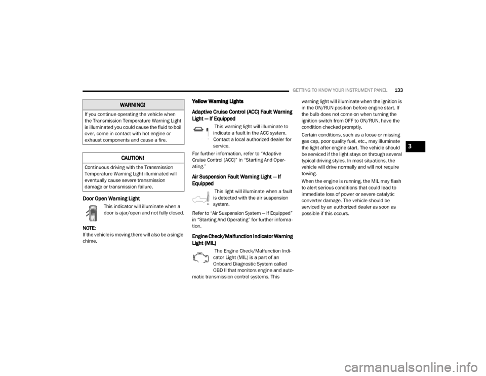
Door Open Warning Light
This indicator will illuminate when a
door is ajar/open and not fully closed.
NOTE:
If the vehicle is moving there will also be a single
chime.
Yellow Warning Lights
Adaptive Cruise Control (ACC) Fault Warning
Light — If Equipped
This warning light will illuminate to
indicate a fault in the ACC system.
Contact a local authorized dealer for
service.
For further information, refer to “Adaptive
Cruise Control (ACC)” in “Starting And Oper -
ating.”
Air Suspension Fault Warning Light — If
Equipped
This light will illuminate when a fault
is detected with the air suspension
system.
Refer to “Air Suspension System — If Equipped”
in “Starting And Operating” for further informa -
tion.
Engine Check/Malfunction Indicator Warning
Light (MIL)
The Engine Check/Malfunction Indi -
cator Light (MIL) is a part of an
Onboard Diagnostic System called
OBD II that monitors engine and auto -
matic transmission control systems. This warning light will illuminate when the ignition is
in the ON/RUN position before engine start. If
the bulb does not come on when turning the
ignition switch from OFF to ON/RUN, have the
condition checked promptly.
Certain conditions, such as a loose or missing
gas cap, poor quality fuel, etc., may illuminate
the light after engine start. The vehicle should
be serviced if the light stays on through several
typical driving styles. In most situations, the
vehicle will drive normally and will not require
towing.
When the engine is running, the MIL may flash
to alert serious conditions that could lead to
immediate loss of power or severe catalytic
converter damage. The vehicle should be
serviced by an authorized dealer as soon as
possible if this occurs.
WARNING!
If you continue operating the vehicle when
the Transmission Temperature Warning Light
is illuminated you could cause the fluid to boil
over, come in contact with hot engine or
exhaust components and cause a fire.
CAUTION!
Continuous driving with the Transmission
Temperature Warning Light illuminated will
eventually cause severe transmission
damage or transmission failure.
3
20_DJD2_OM_EN_USC_t.book Page 133
Page 137 of 553
GETTING TO KNOW YOUR INSTRUMENT PANEL135
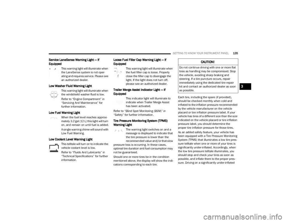
Service LaneSense Warning Light — If
Equipped
This warning light will illuminate when
the LaneSense system is not oper-
ating and requires service. Please see
an authorized dealer.
Low Washer Fluid Warning Light
This warning light will illuminate when
the windshield washer fluid is low.
Refer to “Engine Compartment” in
“Servicing And Maintenance” for
further information.
Low Fuel Warning Light
When the fuel level reaches approxi -
mately 3.2 gal (12 L) this light will turn
on, and remain on until fuel is added.
A single warning chime will sound with
Low Fuel Warning.
Low Coolant Level Warning Light
This telltale will turn on to indicate the
vehicle coolant level is low.
Refer to “Fluids And Lubricants” in
“Technical Specifications” for further
information.
Loose Fuel Filler Cap Warning Light — If
Equipped
This warning light will illuminate when
the fuel filler cap is loose. Properly
close the filler cap to disengage the
light. If the light does not turn off,
please see an authorized dealer.
Trailer Merge Assist Indicator Light — If
Equipped
This indicator light will illuminate to
indicate when Trailer Merge Assist
has been activated.
Refer to “Blind Spot Monitoring (BSM)” in
“Safety” for further information.
Tire Pressure Monitoring System (TPMS)
Warning Light
The warning light switches on and a
message is displayed to indicate that
the tire pressure is lower than the
recommended value and/or that slow
pressure loss is occurring. In these cases,
optimal tire duration and fuel consumption may
not be guaranteed.
Should one or more tires be in the condition
mentioned above, the display will show the indi -
cations corresponding to each tire. Each tire, including the spare (if provided),
should be checked monthly when cold and
inflated to the inflation pressure recommended
by the vehicle manufacturer on the vehicle
placard or tire inflation pressure label. If your
vehicle has tires of a different size than the size
indicated on the vehicle placard or tire inflation
pressure label, you should determine the
proper tire inflation pressure for those tires.
As an added safety feature, your vehicle has
been equipped with a Tire Pressure Monitoring
System (TPMS) that illuminates a low tire pres
-
sure telltale when one or more of your tires is
significantly under-inflated. Accordingly, when
the low tire pressure telltale illuminates, you
should stop and check your tires as soon as
possible, and inflate them to the proper pres -
sure. Driving on a significantly under-inflated
CAUTION!
Do not continue driving with one or more flat
tires as handling may be compromised. Stop
the vehicle, avoiding sharp braking and
steering. If a tire puncture occurs, repair
immediately using the dedicated tire repair
kit and contact an authorized dealer as soon
as possible.
3
20_DJD2_OM_EN_USC_t.book Page 135
Page 142 of 553
140GETTING TO KNOW YOUR INSTRUMENT PANEL
Green Indicator Lights
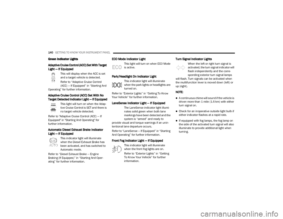
Adaptive Cruise Control (ACC) Set With Target
Light — If Equipped
This will display when the ACC is set
and a target vehicle is detected.
Refer to “Adaptive Cruise Control
(ACC) — If Equipped” in “Starting And
Operating” for further information.
Adaptive Cruise Control (ACC) Set With No
Target Detected Indicator Light — If Equipped
This light will turn on when the Adap -
tive Cruise Control is SET and there is
no target vehicle detected.
Refer to "Adaptive Cruise Control (ACC) — If
Equipped" in "Starting And Operating" for
further information.
Automatic Diesel Exhaust Brake Indicator
Light — If Equipped
This indicator light will illuminate
when the Diesel Exhaust Brake has
been activated, and has switched to
Automatic mode.
Refer to “Diesel Exhaust Brake — Engine
Braking (If Equippes)” in “Starting And Oper -
ating” for further information.
ECO Mode Indicator Light
This light will turn on when ECO Mode
is active.
Park/Headlight On Indicator Light
This indicator light will illuminate
when the park lights or headlights are
turned on.
Refer to “Exterior Lights” in “Getting To Know
Your Vehicle” for further information.
LaneSense Indicator Light — If Equipped
The LaneSense indicator light illumi -
nates solid green when both lane
markings have been detected and the
system is “armed” and ready to
provide visual and torque warnings if an unin -
tentional lane departure occurs.
Refer to “LaneSense — If Equipped” in “Starting
And Operating” for further information.
Front Fog Indicator Light — If Equipped
This indicator light will illuminate
when the front fog lights are on.
Refer to “Exterior Lights” in “Getting
To Know Your Vehicle” for further
information.
Turn Signal Indicator Lights
When the left or right turn signal is
activated, the turn signal indicator will
flash independently and the corre -
sponding exterior turn signal lamps
will flash. Turn signals can be activated when
the multifunction lever is moved down (left) or
up (right).
NOTE:
A continuous chime will sound if the vehicle is
driven more than 1 mile (1.6 km) with either
turn signal on.
Check for an inoperative outside light bulb if
either indicator flashes at a rapid rate.
If equipped with fog lamps, the fog lamp on
the side of the activated turn signal will also
illuminate to provide additional light when
turning.
20_DJD2_OM_EN_USC_t.book Page 140
Page 144 of 553
142GETTING TO KNOW YOUR INSTRUMENT PANEL
technician in making repairs. Although your
vehicle will usually be drivable and not need
towing, see an authorized dealer for service as
soon as possible.
Onboard Diagnostic System (OBD II)
Cybersecurity
Your vehicle is required to have an Onboard
Diagnostic system (OBD II) and a connection
port to allow access to information related to
the performance of your emissions controls.
Authorized service technicians may need to
access this information to assist with the diag-
nosis and service of your vehicle and emissions
system. For further information, refer to “Cybersecurity”
in “Multimedia”.
EMISSIONS INSPECTION AND
MAINTENANCE PROGRAMS
In some localities, it may be a legal requirement
to pass an inspection of your vehicle's emis
-sions control system. Failure to pass could
prevent vehicle registration.
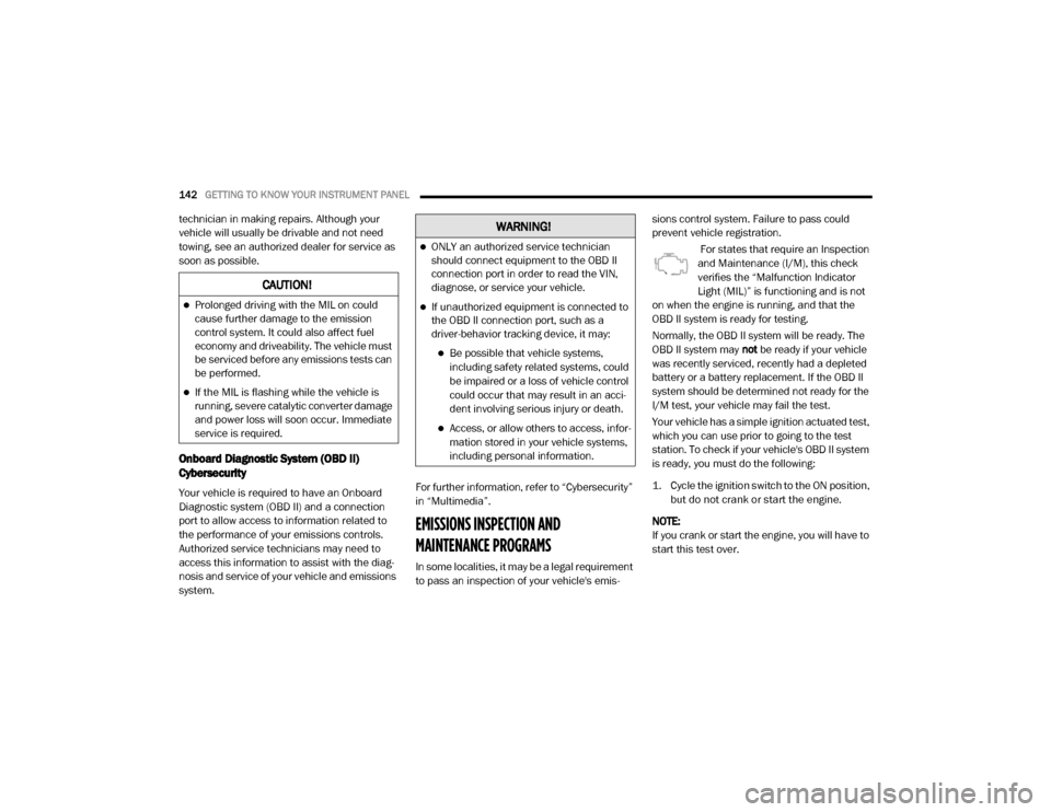
For states that require an Inspection
and Maintenance (I/M), this check
verifies the “Malfunction Indicator
Light (MIL)” is functioning and is not
on when the engine is running, and that the
OBD II system is ready for testing.
Normally, the OBD II system will be ready. The
OBD II system may not be ready if your vehicle
was recently serviced, recently had a depleted
battery or a battery replacement. If the OBD II
system should be determined not ready for the
I/M test, your vehicle may fail the test.
Your vehicle has a simple ignition actuated test,
which you can use prior to going to the test
station. To check if your vehicle's OBD II system
is ready, you must do the following:
1. Cycle the ignition switch to the ON position, but do not crank or start the engine.
NOTE:
If you crank or start the engine, you will have to
start this test over.
CAUTION!
Prolonged driving with the MIL on could
cause further damage to the emission
control system. It could also affect fuel
economy and driveability. The vehicle must
be serviced before any emissions tests can
be performed.
If the MIL is flashing while the vehicle is
running, severe catalytic converter damage
and power loss will soon occur. Immediate
service is required.
WARNING!
ONLY an authorized service technician
should connect equipment to the OBD II
connection port in order to read the VIN,
diagnose, or service your vehicle.
If unauthorized equipment is connected to
the OBD II connection port, such as a
driver-behavior tracking device, it may:
Be possible that vehicle systems, including safety related systems, could
be impaired or a loss of vehicle control
could occur that may result in an acci -
dent involving serious injury or death.
Access, or allow others to access, infor -
mation stored in your vehicle systems,
including personal information.
20_DJD2_OM_EN_USC_t.book Page 142