warning light Ram 2500 2020 Manual Online
[x] Cancel search | Manufacturer: RAM, Model Year: 2020, Model line: 2500, Model: Ram 2500 2020Pages: 553, PDF Size: 21.99 MB
Page 276 of 553

274STARTING AND OPERATING
To Activate
Push the on/off button to activate the Speed
Control. The cruise indicator light in the instru -
ment cluster display will illuminate. To turn the
system off, push the on/off button a second
time. The cruise indicator light will turn off. The
system should be turned off when not in use.
To Set A Desired Speed
Turn the Speed Control on. When the vehicle
has reached the desired speed, push the SET (-)
button and release. Release the accelerator
and the vehicle will operate at the selected
speed.
NOTE:
The vehicle should be traveling at a steady
speed and on level ground before pushing the
SET (-) button.
To Vary The Speed Setting
To Increase Speed
When the Speed Control is set, you can increase
speed by pushing the RES (+) button.
The driver’s preferred units can be selected
through the instrument panel settings (if
equipped). Refer to “Getting To Know Your
Instrument Panel” for more information. The
speed increment shown is dependent on the
chosen speed unit of U.S. (mph) or Metric
(km/h):
U.S. Speed (mph)
Pushing the RES (+) button once will result in
a 1 mph increase in set speed. Each subse -
quent tap of the button results in an increase
of 1 mph.
If the button is continually pushed, the set
speed will continue to increase until the
button is released, then the new set speed
will be established.
Metric Speed (km/h)
Pushing the RES (+) button once will result in
a 1 km/h increase in set speed. Each subse -
quent tap of the button results in an increase
of 1 km/h.
If the button is continually pushed, the set
speed will continue to increase until the
button is released, then the new set speed
will be established.
To Decrease Speed
When the Speed Control is set, you can
decrease speed by pushing the SET (-) button.
The driver’s preferred units can be selected
through the instrument panel settings (if
equipped). Refer to “Getting To Know Your
Instrument Panel” for more information. The
speed decrement shown is dependent on the
chosen speed unit of U.S. (mph) or Metric
(km/h):
U.S. Speed (mph)
Pushing the SET (-) button once will result in
a 1 mph decrease in set speed. Each subse -
quent tap of the button results in a decrease
of 1 mph.
If the button is continually pushed, the set
speed will continue to decrease until the
button is released, then the new set speed
will be established.
WARNING!
Leaving the Speed Control system on when
not in use is dangerous. You could
accidentally set the system or cause it to go
faster than you want. You could lose control
and have an accident. Always leave the
system off when you are not using it.
20_DJD2_OM_EN_USC_t.book Page 274
Page 277 of 553

STARTING AND OPERATING275
Metric Speed (km/h)
Pushing the SET (-) button once will result in
a 1 km/h decrease in set speed. Each subse -
quent tap of the button results in a decrease
of 1 km/h.
If the button is continually pushed, the set
speed will continue to decrease until the
button is released, then the new set speed
will be established.
To Accelerate For Passing
Press the accelerator as you would normally.
When the pedal is released, the vehicle will
return to the set speed.
Using Speed Control On Hills
The transmission may downshift on hills to
maintain the vehicle set speed.
NOTE:
The Speed Control system maintains speed up
and down hills. A slight speed change on
moderate hills is normal.
On steep hills, a greater speed loss or gain may
occur so it may be preferable to drive without
Speed Control.
To Resume Speed
To resume a previously set speed, push the RES
(+) button and release. Resume can be used at
any speed above 20 mph (32 km/h).
To Deactivate
A soft tap on the brake pedal, pushing the
CANCEL button, or normal brake pressure while
slowing the vehicle will deactivate the Speed
Control without erasing the set speed from
memory.
Pushing the on/off button, or placing the igni -
tion in the OFF position, erases the set speed
from memory. The following conditions will also deactivate the
Speed Control without erasing the set speed
from memory:
Vehicle parking brake is applied
Stability event occurs
Gear selector is moved out of DRIVE
Engine overspeed occurs
ADAPTIVE CRUISE CONTROL (ACC) — IF
EQUIPPED
Adaptive Cruise Control (ACC) increases the
driving convenience provided by cruise control
while traveling on highways and major road
-
ways. However, it is not a safety system and not
designed to prevent collisions. Speed Control
function performs differently. Please refer to
the proper section within this chapter.
ACC will allow you to keep cruise control
engaged in light to moderate traffic conditions
without the constant need to reset your cruise
control. ACC utilizes a radar sensor and a
forward facing camera designed to detect a
vehicle directly ahead of you.
WARNING!
Speed Control can be dangerous where the
system cannot maintain a constant speed.
Your vehicle could go too fast for the
conditions, and you could lose control and
have an accident. Do not use Speed Control
in heavy traffic or on roads that are winding,
icy, snow-covered or slippery.
5
20_DJD2_OM_EN_USC_t.book Page 275
Page 284 of 553

282STARTING AND OPERATING
NOTE:
The brake lights will illuminate whenever the
ACC system applies the brakes.
A Proximity Warning will alert the driver if ACC
predicts that its maximum braking level is not
sufficient to maintain the set distance. If this
occurs, a visual alert “BRAKE” will flash in the
instrument cluster display and a chime will
sound while ACC continues to apply its
maximum braking capacity.
Brake Alert
NOTE:
The “BRAKE!” Screen in the instrument cluster
display is a warning for the driver to take action
and does not necessarily mean that the
Forward Collision Warning system is applying
the brakes autonomously. Trailer Detect — If Equipped
When a trailer is detected, the ACC system auto
-
matically defaults to the longest setting (four
bars). The setting can be overridden by pushing
the Distance Button on the steering wheel.
Overtake Aid
When driving with ACC engaged and following a
vehicle, the system will provide an additional
acceleration up to the ACC set speed to assist in
passing the vehicle. This additional acceleration
is triggered when the driver utilizes the left turn
signal and will only be active when passing on
the left hand side.
ACC Operation At Stop
In the event that the ACC system brings your
vehicle to a standstill while following a target
vehicle, if the target vehicle starts moving within
two seconds of your vehicle coming to a stand -
still, your vehicle will resume motion without the
need for any driver action.
If the target vehicle does not start moving within
two seconds of your vehicle coming to a stand -
still, then ACC will cancel and the driver must
take over braking. When the target vehicle
drives off, ACC can be resumed by releasing the
brake and pushing the RES (+) button. NOTE:
After the ACC system holds your vehicle at a
standstill for approximately two seconds, a chime
will sound and an “ACC may cancel soon” warning
will display. The brakes will release when ACC is
canceled and the driver must take over braking.
While ACC is holding your vehicle at a standstill, if
the driver seatbelt is unbuckled or the driver door
is opened, the ACC system will cancel and the
brakes will release. Driver intervention will be
required at this mo ment.
Adaptive Cruise Control (ACC) Menu
The instrument cluster display will show the
current ACC system settings. The instrument
cluster display is located in the center of the
instrument cluster. The information it displays
depends on ACC system status.
WARNING!
When the ACC system is resumed, the driver
must ensure that there are no pedestrians,
vehicles or objects in the path of the vehicle.
Failure to follow these warnings can result in
a collision and death or serious personal
injury.
20_DJD2_OM_EN_USC_t.book Page 282
Page 290 of 553

288STARTING AND OPERATING
To Set A Desired Speed
Turn the Normal (Fixed Speed) Cruise
Control on. When the vehicle has
reached the desired speed, push the
RES (+) or SET (-) button and release.
Release the accelerator and the vehicle will
operate at the selected speed. Once a speed
has been set a message “CRUISE CONTROL SET
TO MPH (km/h)” will appear indicating what
speed was set. This light will turn on when the
system is turned on via the on/off control. It
turns green when the cruise control is set.
To Vary The Speed Setting
To Increase Speed
When the Normal (Fixed Speed) Cruise Control
is set, you can increase speed by pushing the
RES (+) button.
The driver's preferred units can be selected
through the instrument panel settings. Refer to
“Instrument Cluster Display” in “Getting To
Know Your Instrument Panel” for more informa-
tion. The speed increment shown is dependent
on the speed of U.S. (mph) or Metric (km/h)
units:
U.S. Speed (mph)
Pushing the RES (+) button once will result in
a 1 mph increase in set speed. Each subse -
quent tap of the button results in an increase
of 1 mph.
If the button is continually pushed, the set
speed will continue to increase in 5 mph
increments until the button is released. The
increase in set speed is reflected in the
instrument cluster display. Metric Speed (km/h)
Pushing the RES (+) button once will result in
a 1 km/h increase in set speed. Each subse -
quent tap of the button results in an increase
of 1 km/h.
If the button is continually pushed, the set
speed will continue to increase in 10 km/h
increments until the button is released. The
increase in set speed is reflected in the
instrument cluster display.
To Decrease Speed
When the Normal (Fixed Speed) Cruise Control
is set, you can decrease speed by pushing the
SET (-) button.
The driver's preferred units can be selected
through the instrument panel settings. Refer to
“Instrument Cluster Display” in “Getting To
Know Your Instrument Panel” for more informa-
tion. The speed decrement shown is dependent
on the speed of U.S. (mph) or Metric (km/h)
units:
U.S. Speed (mph)
Pushing the SET (-) button once will result in
a 1 mph decrease in set speed. Each subse -
WARNING!
In the Normal (Fixed Speed) Cruise Control
mode, the system will not react to vehicles
ahead. In addition, the proximity warning
does not activate and no alarm will sound
even if you are too close to the vehicle ahead
since neither the presence of the vehicle
ahead nor the vehicle-to-vehicle distance is
detected. Be sure to maintain a safe distance
between your vehicle and the vehicle ahead.
Always be aware which mode is selected.
20_DJD2_OM_EN_USC_t.book Page 288
Page 314 of 553

312STARTING AND OPERATING
(Continued)
ENGINE RUNAWAY — DIESEL ENGINE
Diesel engine runaway is a rare condition
affecting diesel engines, where the engine
consumes its own lubrication oil and runs at
higher and higher RPM until it overspeeds to a
point where it destroys itself due to either
mechanical failure or engine seizure through
lack of lubrication.
REFUELING THE VEHICLE — GAS ENGINE
The fuel filler cap (gas cap) is located behind the
fuel filler door, on the left side of the vehicle.
Open the fuel door and remove the fuel filler cap
by turning it counter-clockwise.
Fuel Filler Cap
NOTE:
When removing the fuel filler cap, lay the cap
tether in the hook, located on the fuel filler door.
WARNING!
In case of engine runaway due to flammable
fumes from fuel spills or turbocharger oil
leaks being sucked into the engine, do the
following to help avoid personal injury and/or
vehicle damage:
1. Turn the ignition switch to the OFF position.
2. Using a CO2 or dry chemical type fire
extinguisher, direct the spray from the fire
extinguisher into the grille on the driver side
so that the spray enters the engine air intake.
The inlet for the engine air intake is located
behind the drivers side headlamp and
receives air through the grille.
WARNING!
Never have any smoking materials lit in or
near the vehicle when the gas cap is
removed or the tank is being filled.
Never add fuel to the vehicle when the
engine is running.
A fire may result if gasoline is pumped into
a portable container that is inside of a
vehicle. You could be burned. Always place
gas containers on the ground while filling.
CAUTION!
Damage to the fuel system or emissions
control system could result from using an
improper fuel tank filler tube cap.
A poorly fitting fuel filler cap could let impu -
rities into the fuel system.
A poorly fitting fuel filler cap may cause the
“Malfunction Indicator Light (MIL)” to turn
on.
To avoid fuel spillage and overfilling, do not
“top off” the fuel tank after filling. When the
fuel nozzle “clicks” or shuts off, the fuel
tank is full.
WARNING! (Continued)
20_DJD2_OM_EN_USC_t.book Page 312
Page 316 of 553

314STARTING AND OPERATING
(Continued)
3. Fill the vehicle with fuel – when the fuel nozzle “clicks” or shuts off the fuel tank is
full.
4. Remove the fuel nozzle and close the fuel door.
Emergency Fuel Can Refueling
NOTE:
In the event that you run the vehicle out of fuel,
once refueled, place the ignition in the ON posi -
tion for 30 seconds, then turn the ignition OFF
and wait 30 seconds. Repeat this procedure
three times, prior to cranking the engine.
Most fuel cans will not open the flapper door.
A funnel is provided to open the flapper door to
allow emergency refueling with a fuel can.
1. Retrieve fuel funnel from the jack kit located under the front passenger seat.
2. Insert funnel into same filler pipe opening as the fuel nozzle.
Fill Locations And Funnel Usage
NOTE:
Ensure funnel is inserted fully to hold flapper
door open.
3. Pour fuel into funnel opening.
4. Remove funnel from filler pipe, clean off prior to putting back in the jack kit.
Diesel Exhaust Fluid
Your vehicle is equipped with a Selective Cata-
lytic Reduction (SCR) system to meet the very
stringent diesel emissions standards required
by the Environmental Protection Agency.
The purpose of the SCR system is to reduce
levels of NOx (oxides of nitrogen emitted from
engines) that are harmful to our health and the
environment to a near-zero level. A small quan -
tity of Diesel Exhaust Fluid (DEF) is injected into
the exhaust upstream of a catalyst where, when
1 — Diesel Exhaust Fluid (DEF) Fill Location
2 — Emergency Diesel Fuel Fill Funnel
3 — Diesel Fuel Fill Location
WARNING!
Never have any smoking materials lit in or
near the vehicle when the fuel door is open
or the tank is being filled.
Never add fuel when the engine is running.
This is in violation of most state and federal
fire regulations and may cause the
“Malfunction Indicator Light” to turn on.
A fire may result if fuel is pumped into a
portable container that is inside of a
vehicle. You could be burned. Always place
fuel containers on the ground while filling.
CAUTION!
To avoid fuel spillage and overfilling, do not
“top off” the fuel tank after filling.
WARNING! (Continued)
20_DJD2_OM_EN_USC_t.book Page 314
Page 322 of 553

320STARTING AND OPERATING
distributing (load equalizing) hitch are recom -
mended for heavier Tongue Weights (TW) and
may be required depending on vehicle and
trailer configuration/loading to comply with
GAWR requirements.
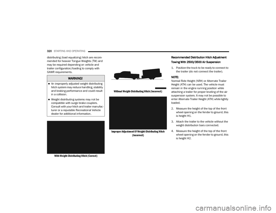
With Weight-Distributing Hitch (Correct) Without Weight-Distributing Hitch (Incorrect)
Improper Adjustment Of Weight-Distributing Hitch (Incorrect)
Recommended Distribution Hitch Adjustment
Towing With 2500/3500 Air Suspension
1. Position the truck to be ready to connect to
the trailer (do not connect the trailer).
NOTE:
Normal Ride Height (NRH) or Alternate Trailer
Height (ATH) can be used. The vehicle must
remain in the engine running position while
attaching a trailer for proper leveling of the air
suspension system. It may not be possible to
enter Alternate Trailer Height (ATH) while lightly
loaded.
2. Measure the height of the top of the front wheel opening on the fender to ground, this
is height H1.
3. Attach the trailer to the vehicle without the weight distribution bars connected.
4. Measure the height of the top of the front wheel opening on the fender to ground, this
is height H2.
WARNING!
An improperly adjusted weight distributing
hitch system may reduce handling, stability
and braking performance and could result
in a collision.
Weight distributing systems may not be
compatible with surge brake couplers.
Consult with your hitch and trailer manufac -
turer or a reputable Recreational Vehicle
dealer for additional information.
20_DJD2_OM_EN_USC_t.book Page 320
Page 327 of 553

STARTING AND OPERATING325
Integrated Trailer Brake Module — If
Equipped
Your vehicle may have an Integrated Trailer
Brake Module (ITBM) for Electric and Electric
Over Hydraulic (EOH) trailer brakes. NOTE:
This module has been designed and verified
with electric trailer brakes and new electric over
hydraulic systems. Some previous EOH systems
may not be compatible with ITBM.
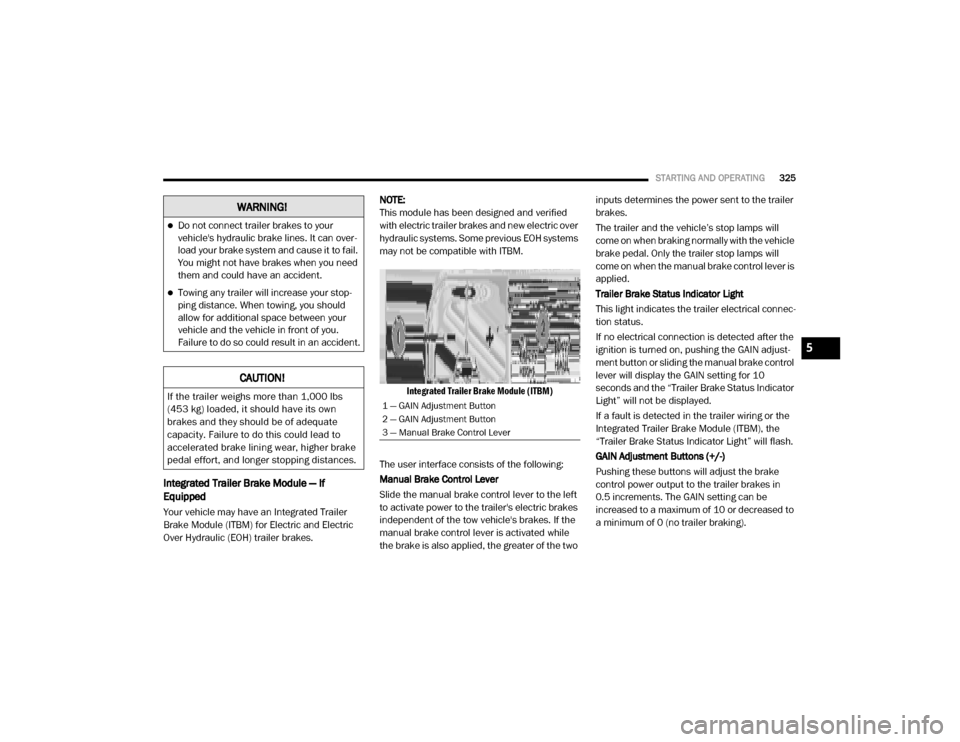
Integrated Trailer Brake Module (ITBM)
The user interface consists of the following:
Manual Brake Control Lever
Slide the manual brake control lever to the left
to activate power to the trailer's electric brakes
independent of the tow vehicle's brakes. If the
manual brake control lever is activated while
the brake is also applied, the greater of the two inputs determines the power sent to the trailer
brakes.
The trailer and the vehicle’s stop lamps will
come on when braking normally with the vehicle
brake pedal. Only the trailer stop lamps will
come on when the manual brake control lever is
applied.
Trailer Brake Status Indicator Light
This light indicates the trailer electrical connec
-
tion status.
If no electrical connection is detected after the
ignition is turned on, pushing the GAIN adjust -
ment button or sliding the manual brake control
lever will display the GAIN setting for 10
seconds and the “Trailer Brake Status Indicator
Light” will not be displayed.
If a fault is detected in the trailer wiring or the
Integrated Trailer Brake Module (ITBM), the
“Trailer Brake Status Indicator Light” will flash.
GAIN Adjustment Buttons (+/-)
Pushing these buttons will adjust the brake
control power output to the trailer brakes in
0.5 increments. The GAIN setting can be
increased to a maximum of 10 or decreased to
a minimum of 0 (no trailer braking).
WARNING!
Do not connect trailer brakes to your
vehicle's hydraulic brake lines. It can over -
load your brake system and cause it to fail.
You might not have brakes when you need
them and could have an accident.
Towing any trailer will increase your stop -
ping distance. When towing, you should
allow for additional space between your
vehicle and the vehicle in front of you.
Failure to do so could result in an accident.
CAUTION!
If the trailer weighs more than 1,000 lbs
(453 kg) loaded, it should have its own
brakes and they should be of adequate
capacity. Failure to do this could lead to
accelerated brake lining wear, higher brake
pedal effort, and longer stopping distances.1 — GAIN Adjustment Button
2 — GAIN Adjustment Button
3 — Manual Brake Control Lever
5
20_DJD2_OM_EN_USC_t.book Page 325
Page 329 of 553

STARTING AND OPERATING327
* The suggested selection depends and may
change depending on the customer prefer -
ences for braking performance. Condition of the
trailer brakes, driving and road state may also
affect the selection.
Display Messages
The trailer brake control interacts with the
instrument cluster display. Display messages,
along with a single chime, will be displayed
when a malfunction is determined in the trailer
connection, trailer brake control, or on the
trailer. Refer to “Instrument Cluster Display” in
“Getting To Know Your Instrument Panel” for
further information. NOTE:
An aftermarket controller may be available
for use with trailers with air or elec
-
tric-over-hydraulic trailer brake systems. To
determine the type of brakes on your trailer
and the availability of controllers, check with
your trailer manufacturer or dealer.
Removal of the ITBM will cause errors and it
may cause damage to the electrical system
and electronic modules of the vehicle. See
your authorized dealer if an aftermarket
module is to be installed.
Towing Requirements — Trailer Lights And
Wiring
Whenever you pull a trailer, regardless of the
trailer size, stoplights and turn signals on the
trailer are required for motoring safety.
The Trailer Tow Package may include a four- and
seven-pin wiring harness. Use a factory
approved trailer harness and connector.
NOTE:
Do not cut or splice wiring into the vehicle’s
wiring harness.
The electrical connections are all complete to
the vehicle but you must mate the harness to a
trailer connector. Refer to the following illustra -
tions.
Light Electric Heavy Electric Light EOHHeavy EOH
Type of Trailer Brakes Electric Trailer Brakes Electric Trailer Brakes Electric over Hydraulic
Trailer BrakesElectric over Hydraulic
Trailer Brakes
Load *Under 10,000 lbs *Above 10,000 lbs *Under 10,000 lbs *Above 10,000 lbs
WARNING!
Connecting a trailer that is not compatible
with the ITBM system may result in reduced
or complete loss of trailer braking. There may
be a increase in stopping distance or trailer
instability which could result in personal
injury.
CAUTION!
Connecting a trailer that is not compatible
with the ITBM system may result in reduced
or complete loss of trailer braking. There may
be a increase in stopping distance or trailer
instability which could result in damage to
your vehicle, trailer, or other property.
5
20_DJD2_OM_EN_USC_t.book Page 327
Page 331 of 553

STARTING AND OPERATING329
Speed Control — If Equipped
Do not use on hilly terrain or with heavy
loads.
When using the Speed Control, if you experi -
ence speed drops greater than 10 mph
(16 km/h), disengage until you can get back
to cruising speed.
Use Speed Control in flat terrain and with
light loads to maximize fuel efficiency.
Cooling System
To reduce potential for engine and transmission
overheating, take the following actions:
City Driving
In city traffic — while stopped, place the trans -
mission in NEUTRAL, but do not increase
engine idle speed.
Highway Driving
Reduce speed.
Temporarily turn off air conditioning.
Air Suspension System
To aid in attaching/detaching the trailer from
the vehicle, the air suspension system can be
used. Refer to “Air Suspension System” in “Starting And Operating” for further informa
-
tion.
NOTE:
The vehicle must remain in the engine running
position while attaching a trailer for proper
leveling of the air suspension system.
SNOWPLOW
Snowplow Prep Packages are available as a
factory installed option. These packages
include components necessary to equip your
vehicle with a snowplow.
NOTE:
Before installation of a snowplow it is highly
recommended that the owner/installer obtain
and follow the recommendations contained
within the current Body Builders Guide. See
your authorized dealer, installer or snowplow
manufacturer for this information. There are
unique electrical systems that must be
connected to properly ensure operator safety
and prevent overloading vehicle systems.
Before Plowing
Check the hydraulic system for leaks and
proper fluid level.
Check the mounting bolts and nuts for proper
tightness.
Check the runners and cutting edge for
excessive wear. The cutting edge should be
¼ to ½ inches (6 cm to 1.2 cm) above ground
in snow plowing position.
Check that snowplow lighting is connected
and functioning properly.
WARNING!
Attaching a snowplow to this vehicle could
adversely affect performance of the airbag
system in a collision. Do not expect that the
airbag will perform as described earlier in this
manual.
CAUTION!
The “Lamp Out” indicator could illuminate if
exterior lamps are not properly installed.
5
20_DJD2_OM_EN_USC_t.book Page 329