audio Ram 2500 2020 Owner's Manual
[x] Cancel search | Manufacturer: RAM, Model Year: 2020, Model line: 2500, Model: Ram 2500 2020Pages: 553, PDF Size: 21.99 MB
Page 11 of 553

9
TECHNICAL SPECIFICATIONS
IDENTIFICATION DATA ...................................... 444Vehicle Identification Number ................. 444
BRAKE SYSTEM ................................................ 444
Hydraulic Brake Assist — If Equipped .......444
WHEEL AND TIRE TORQUE
SPECIFICATIONS ................................................ 444
Torque Specifications ................................444
FUEL REQUIREMENTS — GAS ENGINE ............ 446
6.4L Engine ................................................446
Reformulated Gasoline .............................446
Materials Added To Fuel ...........................446
Gasoline/Oxygenate Blends......................446
Do Not Use E-85 In Non-Flex Fuel
Vehicles ......................................................447 CNG And LP Fuel System Modifications ...447
MMT In Gasoline ........................................447
Fuel System Cautions ................................447
Carbon Monoxide Warnings ......................448
FUEL REQUIREMENTS – DIESEL ENGINE ...... 448
Fuel Specifications ...................................448
Biodiesel Fuel Requirements ....................449
FLUID CAPACITIES — GAS ENGINE .................. 451
FLUID CAPACITIES — DIESEL ENGINE............. 451
FLUIDS AND LUBRICANTS — GAS ENGINE ..... 452
Engine ........................................................ 452
Chassis .......................................................454 FLUIDS AND LUBRICANTS — DIESEL
ENGINE ................................................................ 454
Engine ........................................................ 454
Chassis ....................................................... 457
MULTIMEDIA
UCONNECT SYSTEMS .......................................458
CYBERSECURITY ............................................... 458
UCONNECT SETTINGS ........................................ 459
Uconnect 3 Settings .................................. 459
Uconnect 4/4C/4C NAV Settings ............. 473
Uconnect 4C NAV With 12-inch Display
Settings ...................................................... 493
SAFETY AND GENERAL INFORMATION ........... 511
Safety Guidelines....................................... 511
UCONNECT 3 WITH 5-INCH DISPLAY ..............512
Introduction................................................ 512
Radio Mode ................................................ 513
Media Mode ............................................... 516
Phone Mode ............................................... 518
STEERING WHEEL AUDIO CONTROLS — IF
EQUIPPED ...........................................................525
Radio Operation ......................................... 525
Media Mode ............................................... 525
IPOD®/USB/MP3 CONTROL —
IF EQUIPPED ....................................................... 525 RADIO OPERATION AND MOBILE PHONES.... 527
Regulatory And Safety Information .......... 527
VOICE RECOGNITION QUICK TIPS .................. 529
Introducing Uconnect ................................ 529
Get Started................................................. 529
Basic Voice Commands ............................ 529
Radio .......................................................... 530
Media ......................................................... 530
Phone ......................................................... 531
Voice Text Reply — If Equipped ................. 531
Climate (4C/4C NAV)................................. 532
Navigation (4C NAV) .................................. 532
Siri® Eyes Free — If Equipped ................. 532
Using Do Not Disturb ................................ 532
Android Auto™ — If Equipped .................. 533
Apple CarPlay® — If Equipped ................. 533
General Information .................................. 534
Additional Information............................... 534
CUSTOMER ASSISTANCE
SUGGESTIONS FOR OBTAINING SERVICE FOR
YOUR VEHICLE .................................................. 536
Prepare For The Appointment .................. 536
Prepare A List............................................. 536
Be Reasonable With Requests ................. 536
20_DJD2_OM_EN_USC_t.book Page 9
Page 120 of 553
118GETTING TO KNOW YOUR INSTRUMENT PANEL
display located on the instrument panel, your
instrument cluster display can show you how
systems are working and give you warnings
when they are not. The steering wheel mounted
controls allow you to scroll through the main
menus and submenus. You can access the
specific information you want and make selec-
tions and adjustments.
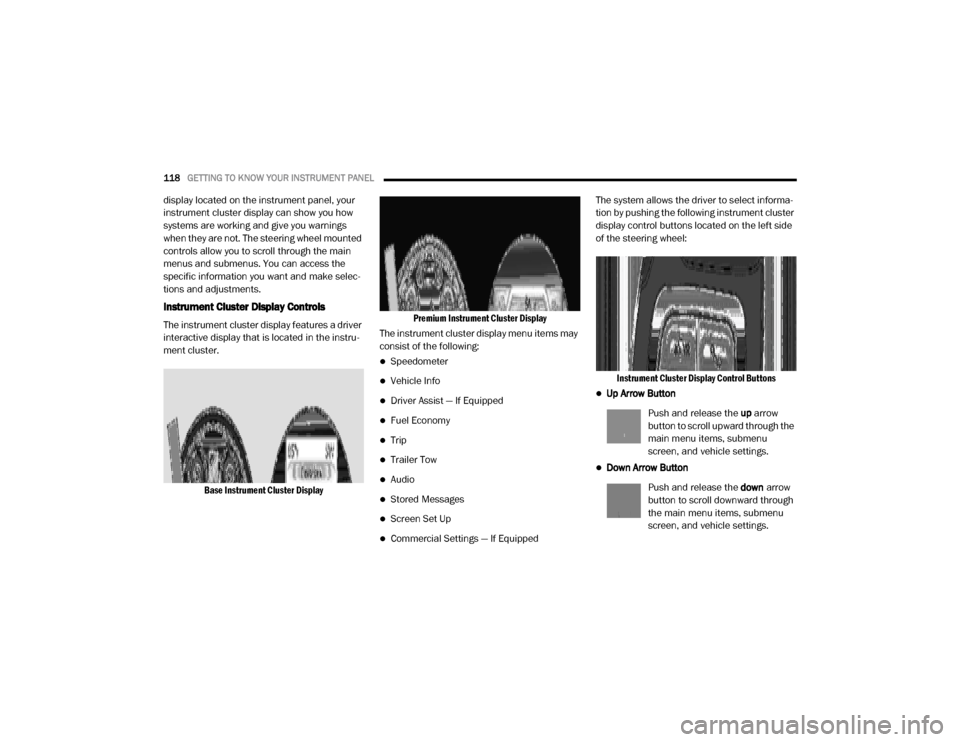
Instrument Cluster Display Controls
The instrument cluster display features a driver
interactive display that is located in the instru -
ment cluster.
Base Instrument Cluster Display Premium Instrument Cluster Display
The instrument cluster display menu items may
consist of the following:
Speedometer
Vehicle Info
Driver Assist — If Equipped
Fuel Economy
Trip
Trailer Tow
Audio
Stored Messages
Screen Set Up
Commercial Settings — If Equipped The system allows the driver to select informa
-
tion by pushing the following instrument cluster
display control buttons located on the left side
of the steering wheel:
Instrument Cluster Display Control Buttons
Up Arrow Button
Push and release the up arrow
button to scroll upward through the
main menu items, submenu
screen, and vehicle settings.
Down Arrow Button
Push and release the down arrow
button to scroll downward through
the main menu items, submenu
screen, and vehicle settings.
20_DJD2_OM_EN_USC_t.book Page 118
Page 123 of 553
GETTING TO KNOW YOUR INSTRUMENT PANEL121
LaneSense — If Equipped
The instrument cluster display displays the
current LaneSense system settings. The infor-
mation displayed depends on LaneSense
system status and the conditions that need to
be met. For further information, refer to “Lane -
Sense — If Equipped” in “Starting And Oper-
ating.”
Fuel Economy
Push and release the up or down arrow button
until the Fuel Economy menu item is highlighted
in the instrument cluster display. Push and Hold
the right arrow button to reset Average Fuel
Economy.
Current Fuel Economy Gauge
Average Fuel Economy Value
Range To Empty
Trip A/Trip B
Push and release the up or down arrow button
until the Trip menu item is highlighted in the
instrument cluster display. Push and release
the right arrow button to enter the submenus of
Trip A and Trip B. The Trip A or Trip B information
will display the following:
Distance
Average Fuel Economy
Elapsed Time
Push and hold right arrow button to reset all
information.
Trailer Tow
Push and release the up or down arrow button
until the Trailer Tow menu item is highlighted in
the instrument cluster display. Push and
release the right arrow button and the next
screen will display the following trailer trip infor -
mation:
Trip Distance (trailer specific): Push and hold
the right arrow button to reset the distance.
Trailer Brake
Output
Type
Gain
Trailer Tire Pressure — If Equipped
Audio
Push and release the up or down arrow button
until the Audio Menu icon/title is highlighted in
the instrument cluster display. This menu will
display the audio source information, including the Song name, Artist name, and audio source
with an accompanying graphic.
Phone Call Status
When a call is incoming, a Phone Call Status
pop-up will display on the screen. The pop-up
will remain until the phone is answered or
ignored.
NOTE:
The call status will temporarily replace the
previous media source information displayed
on the screen. When the pop-up is no longer
displayed, the display will return to the last used
screen.
Stored Messages
Push and release the
up or down arrow button
until the Messages Menu item is highlighted.
This feature shows the number of stored
warning messages. Push and release the right
or left arrow buttons to cycle through stored
messages.
Screen Setup Menu Item
Push and release the up or down arrow button
until the Screen Setup menu item is highlighted
in the instrument cluster display. Push and
release the right arrow button to enter the
Screen Setup submenu. The Screen Setup
3
20_DJD2_OM_EN_USC_t.book Page 121
Page 124 of 553
122GETTING TO KNOW YOUR INSTRUMENT PANEL
feature allows you to change what information
is displayed in the instrument cluster as well as
the location that information is displayed.
Current Gear
Off (Default Setting)
On
Odometer
Unit Without Decimal (Default Setting)
Unit With Decimal
Favorite Menu
Speedometer
Vehicle Info
Driver Assist (Show/Hide) — If Equipped
Fuel Economy (Show/Hide)
Trip Info (Show/Hide)
Trailer Tow (Show/Hide)
Audio (Show/Hide)
Messages
Screen Setup
Commercial Settings — If Equipped NOTE:
Menus with (Show/Hide) can push the
Right
arrow button to choose whether to show or hide
this menu in the instrument cluster display.
Upper Left
None
Compass (Default Setting) — If Equipped
Outside Temp — If Equipped
Time
Range To Empty
Average MPG
Current MPG
Trip A Distance
Trip B Distance
Trailer Trip — If Equipped
Trailer Brake — If Equipped
Oil Pressure — If Equipped
Coolant Temperature — If Equipped
Oil Temperature — If Equipped
Battery Voltage — If Equipped
Transmission Temperature — If Equipped
Oil Life — If Equipped
Exhaust Brake — If Equipped
Turbo Boost — If Equipped
Fuel Filter Life — If Equipped
Upper Center
None
Compass
Outside Temp
Time
Range To Empty
Average MPG
Current MPG
Trip A Distance
Trip B Distance
Trailer Trip
Audio
Speedometer (Default Setting)
Menu Title
20_DJD2_OM_EN_USC_t.book Page 122
Page 131 of 553
GETTING TO KNOW YOUR INSTRUMENT PANEL129
NOTE:
The charging system is independent from
load reduction. The charging system
performs a diagnostic on the charging
system continuously.
If the Battery Charge Warning Light is on it
may indicate a problem with the charging
system. Refer to “Warning Lights And
Messages” in “Getting To Know Your Instru-
ment Panel” for further information.
The electrical loads that may be switched off (if
equipped), and vehicle functions which can be
affected by load reduction:
Heated Seats/Vented Seats/Heated Wheel
Rear Defroster And Heated Mirrors
HVAC System
115 Volts AC Power Inverter System
Audio and Telematics System Loss of the battery charge may indicate one or
more of the following conditions:
The charging system cannot deliver enough
electrical power to the vehicle system
because the electrical loads are larger than
the capability of charging system. The
charging system is still functioning properly.
Turning on all possible vehicle electrical
loads (e.g. HVAC to max settings, exterior and
interior lights, overloaded power outlets
+12 Volts, 115 Volts AC, USB ports) during
certain driving conditions (city driving,
towing, frequent stopping).
Installing options like additional lights,
upfitter electrical accessories, audio
systems, alarms and similar devices.
Unusual driving cycles (short trips separated
by long parking periods).
The vehicle was parked for an extended
period of time (weeks, months).
The battery was recently replaced and was
not charged completely.
The battery was discharged by an electrical
load left on when the vehicle was parked.
The battery was used for an extended period
with the engine not running to supply radio,
lights, chargers, +12 Volts portable appli
-
ances like vacuum cleaners, game consoles
and similar devices.
What to do when an electrical load reduction
action message is present (“Battery Saver On”
or “Battery Saver Mode”)
During a trip:
Reduce power to unnecessary loads if
possible:
Turn off redundant lights (interior or exte -
rior).
Check what may be plugged in to power outlets +12 Volts, 115 Volts AC, USB
ports.
Check HVAC settings (blower, tempera -
ture).
Check the audio settings (volume).
3
20_DJD2_OM_EN_USC_t.book Page 129
Page 132 of 553
130GETTING TO KNOW YOUR INSTRUMENT PANEL
After a trip:
Check if any aftermarket equipment was
installed (additional lights, upfitter electrical
accessories, audio systems, alarms) and
review specifications if any (load and Ignition
Off Draw currents).
Evaluate the latest driving cycles (distance,
driving time and parking time).
The vehicle should have service performed if
the message is still present during consecu-
tive trips and the evaluation of the vehicle
and driving pattern did not help to identify the
cause.
WARNING LIGHTS AND MESSAGES
The warning/indicator lights will illuminate in
the instrument panel together with a dedicated
message and/or acoustic signal when appli -
cable. These indications are indicative and
precautionary and as such must not be consid -
ered as exhaustive. Always refer to the informa-
tion in this chapter in the event of a failure
indication. All active telltales will display first if
applicable. The system check menu may
appear different based upon equipment
options and current vehicle status. Some tell -
tales are optional and may not appear.
Red Warning Lights
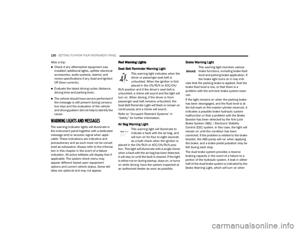
Seat Belt Reminder Warning Light
This warning light indicates when the
driver or passenger seat belt is
unbuckled. When the ignition is first
placed in the ON/RUN or ACC/ON/
RUN position and if the driver’s seat belt is
unbuckled, a chime will sound and the light will
turn on. When driving, if the driver or front
passenger seat belt remains unbuckled, the
Seat Belt Reminder Light will flash or remain on
continuously and a chime will sound.
Refer to “Occupant Restraint Systems” in
“Safety” for further information.
Air Bag Warning Light
This warning light will illuminate to
indicate a fault with the air bag, and
will turn on for four to eight seconds
as a bulb check when the ignition is
placed in the ON/RUN or ACC/ON/RUN posi -
tion. This light will illuminate with a single chime
when a fault with the air bag has been detected,
it will stay on until the fault is cleared. If the light
is either not on during startup, stays on, or turns
on while driving, have the system inspected at
an authorized dealer as soon as possible.
Brake Warning Light
This warning light monitors various
brake functions, including brake fluid
level and parking brake application. If
the brake light turns on it may indi -
cate that the parking brake is applied, that the
brake fluid level is low, or that there is a
problem with the anti-lock brake system reser -
voir.
If the light remains on when the parking brake
has been disengaged, and the fluid level is at
the full mark on the master cylinder reservoir, it
indicates a possible brake hydraulic system
malfunction or that a problem with the Brake
Booster has been detected by the Anti-Lock
Brake System (ABS) / Electronic Stability
Control (ESC) system. In this case, the light will
remain on until the condition has been
corrected. If the problem is related to the brake
booster, the ABS pump will run when applying
the brake, and a brake pedal pulsation may be
felt during each stop.
The dual brake system provides a reserve
braking capacity in the event of a failure to a
portion of the hydraulic system. A leak in either
half of the dual brake system is indicated by the
Brake Warning Light, which will turn on when
20_DJD2_OM_EN_USC_t.book Page 130
Page 245 of 553
STARTING AND OPERATING243
Torque Converter Clutch
A feature designed to improve fuel economy
has been included in the automatic transmis -
sion on your vehicle. A clutch within the torque
converter engages automatically at calibrated
speeds. This may result in a slightly different
feeling or response during normal operation in
the upper gears. When the vehicle speed drops
or during some accelerations, the clutch auto -
matically disengages.
NOTE:
The torque converter clutch will not engage,
until the transmission fluid and engine
coolant are warm [usually after 1 to 3 miles
(2 to 5 km) of driving]. Because engine speed
is higher when the torque converter clutch is
not engaged, it may seem as if the transmis -
sion is not shifting properly when cold. This is normal. Using the Electronic Range Select
(ERS) shift control, when the transmission is
sufficiently warm, will demonstrate that the
transmission is able to shift into and out of
Overdrive.
If the vehicle has not been driven for several
days, the first few seconds of operation after
shifting the transmission into gear may seem
sluggish. This is due to the fluid partially
draining from the torque converter into the
transmission. This condition is normal and
will not cause damage to the transmission.
The torque converter will refill within five
seconds after starting the engine.
AUXILIARY SWITCHES — IF EQUIPPED
There can be up to six auxiliary switches located
in the lower switch bank of the instrument panel
which can be used to power various electronic
devices and PTO (Power Take Off) – If Equipped.
If Power Take Off is equipped, it will take the
place of the sixth Auxiliary switch. Connections
to the switches are found under the hood in the
connectors attached to the auxiliary Power
Distribution Center.
You have the ability to configure the function
-
ality of the auxiliary switches via the instrument cluster display. All switches can now be config
-
ured for setting the switch type operation to
latching or momentary, power source of either
battery or ignition, and ability to hold last state
across key cycles.
NOTE:
Holding last state conditions are met when
switch type is set to latching and power source
is set to ignition.
For further information on using the auxiliary
switches, please refer to the Ram Body Builders
Guide by accessing www.rambodybuilder.com
and choosing the appropriate links.
ACTIVE NOISE CANCELLATION
Your vehicle is equipped with an Active Noise
Cancellation system that cannot be turned off.
This system is designed to address exhaust and
engine noise. The system relies on four micro -
phones embedded in the headliner, which
monitor exhaust and engine noise, and assists
an onboard frequency generator, which creates
counteracting sound waves in the audio
system’s speakers. This helps keep the vehicle
quiet at idle and during drive. The system is
deactivated when the windows are rolled down.
WARNING!
Do not use the “TOW/HAUL” feature when
driving in icy or slippery conditions. The
increased engine braking can cause the rear
wheels to slide, and the vehicle to swing
around with the possible loss of vehicle
control, which may cause an accident
possibly resulting in personal injury or death.
5
20_DJD2_OM_EN_USC_t.book Page 243
Page 293 of 553
STARTING AND OPERATING291
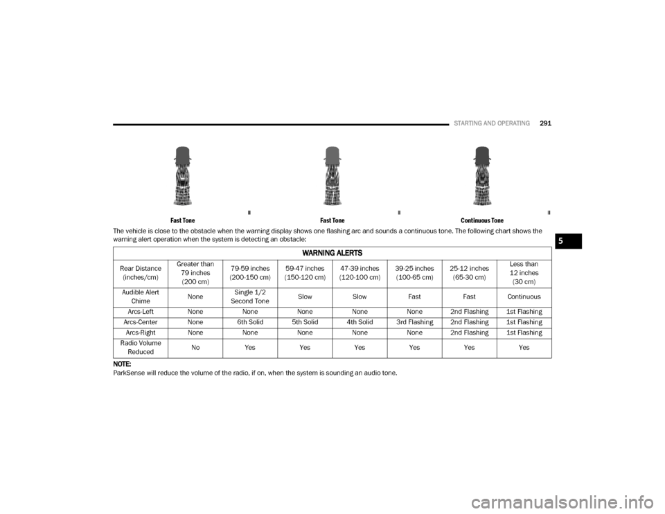
Fast Tone Fast ToneContinuous Tone
The vehicle is close to the obstacle when the warning display shows one flashing arc and sounds a continuous tone. The following chart shows the
warning alert operation when the system is detecting an obstacle:
NOTE:
ParkSense will reduce the volume of the radio, if on, when the system is sounding an audio tone.
WARNING ALERTS
Rear Distance (inches/cm) Greater than
79 inches (200 cm) 79-59 inches
(200-150 cm) 59-47 inches
(150-120 cm) 47-39 inches
(120-100 cm) 39-25 inches
(100-65 cm) 25-12 inches
(65-30 cm) Less than
12 inches (30 cm)
Audible Alert Chime NoneSingle 1/2
Second Tone Slow
Slow FastFast Continuous
Arcs-Left None NoneNoneNoneNone 2nd Flashing 1st Flashing
Arcs-Center None 6th Solid 5th Solid 4th Solid 3rd Flashing 2nd Flashing 1st Flashing Arcs-Right None NoneNoneNoneNone 2nd Flashing 1st Flashing
Radio Volume Reduced No
Yes YesYesYesYesYes
5
20_DJD2_OM_EN_USC_t.book Page 291
Page 299 of 553
STARTING AND OPERATING297
NOTE:
ParkSense will reduce the volume of the radio,
if on, when the system is sounding an audio
tone.
Front Park Assist Audible Alerts
ParkSense will turn off the Front Park Assist
audible alert (chime) after approximately three
seconds when an obstacle has been detected,
the vehicle is stationary, and brake pedal is
applied.
Adjustable Chime Volume Settings
The Front and Rear chime volume settings are
programmable through the Uconnect system.
Refer to “Uconnect Settings” in “Multimedia”
for further information. The chime volume settings include low,
medium, and high. The factory default volume is
medium.
Enabling And Disabling Front And/Or Rear
ParkSense
Front ParkSense can be enabled and disabled
with the Front ParkSense switch.
Rear ParkSense can be enabled and disabled
with the Rear ParkSense switch.
When the gear selector is moved to
REVERSE and the Front or Rear
system is disabled, the instrument
cluster display will show a vehicle
graphic with an “Off” message overlay over the
system that is off (Front or Rear system). This
vehicle graphic will be displayed for as long as
the vehicle is in REVERSE. The Front or Rear ParkSense switch LED will be
on when Front or Rear ParkSense is disabled or
requires service. The Front or Rear ParkSense
switch LED will be off when the Front or Rear
system is enabled. If the Front or Rear Park
-
Sense switch is pushed, and the system
requires service, the Front or Rear ParkSense
switch LED will blink momentarily, and then the
LED will be on.
Service The ParkSense Front/Rear Park
Assist System
During vehicle start up, when the Front/Rear
ParkSense System has detected a faulted
condition, the instrument cluster display will
show the "Front/Rear ParkSense Unavailable
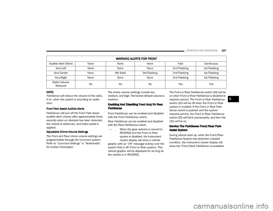
Audible Alert Chime
NoneNoneNone FastContinuous
Arcs-Left NoneNoneNone2nd Flashing 1st Flashing
Arcs-Center None4th Solid 3rd Flashing 2nd Flashing 1st Flashing
Arcs-Right NoneNoneNone2nd Flashing 1st Flashing
Radio Volume Reduced No
NoNo Yes Yes
WARNING ALERTS FOR FRONT
5
20_DJD2_OM_EN_USC_t.book Page 297
Page 341 of 553
IN CASE OF EMERGENCY339
NOTE:
Your vehicle may be transmitting data as
authorized by the subscriber.
The SOS and ASSIST buttons will only func -
tion if you are connected to an operable LTE
(voice/data) or 4G (data) network. Other
Uconnect services will only be operable if
your SiriusXM Guardian™ service is active
and you are connected to an operable LTE
(voice/data) or 4G (data) network. ASSIST Call
The ASSIST Button is used to automatically
connect you to any one of the following support
centers:
Roadside Assistance – If you get a flat tire, or
need a tow, just push the ASSIST button and
you’ll be connected to someone who can
help. Roadside Assistance will know what
vehicle you’re driving and its location. Addi
-
tional fees may apply for roadside assis -
tance.
SiriusXM Guardian™ Customer Care –
In-vehicle support for SiriusXM Guardian™.
Vehicle Customer Care – Total support for all
other vehicle issues.
SOS Call
1. Push the SOS Call button on the overhead console.
NOTE:
In case the SOS Call button is pushed in error,
there will be a 10 second delay before the SOS
Call system initiates a call to a SOS operator. To
cancel the SOS Call connection, push the SOS
call button on the overhead console or press the cancellation button on the Device Screen.
Termination of the SOS Call will turn off the
green LED light on the overhead console.
2. The LED light located between the ASSIST
and SOS buttons on the overhead console
will turn green once a connection to a SOS
operator has been made.
3. Once a connection between the vehicle and a SOS operator is made, the SOS Call
system may transmit the following
important vehicle information to a SOS
operator: Indication that the occupant placed a SOS Call.
The vehicle brand.
The last known GPS coordinates of the vehicle.
4. You should be able to speak with the SOS operator through the vehicle audio system
to determine if additional help is needed.
WARNING!
ALWAYS obey traffic laws and pay attention to
the road. ALWAYS drive safely with your hands
on the steering wheel. You have full
responsibility and assume all risks related to
the use of the features and applications in
this vehicle. Only use the features and
applications when it is safe to do so. Failure
to do so may result in an accident involving
serious injury or death.
6
20_DJD2_OM_EN_USC_t.book Page 339