lock Ram 3500 2020 Owner's Manual
[x] Cancel search | Manufacturer: RAM, Model Year: 2020, Model line: 3500, Model: Ram 3500 2020Pages: 568
Page 287 of 568
STARTING AND OPERATING285
TO SET A DESIRED ACC SPEED
When the vehicle reaches the speed desired,
push the SET (-) button and release. The
instrument cluster display will show the set
speed.
If the system is set when the vehicle speed is
below 20 mph (32 km/h), the set speed shall
be defaulted to 20 mph (32 km/h). If the
system is set when the vehicle speed is above
20 mph (32 km/h), the set speed shall be the
current speed of the vehicle.
NOTE:
ACC cannot be set if there is a stationary vehicle
in front of your vehicle in close proximity.
Remove your foot from the accelerator pedal
after the ACC has been set. If you do not, the
vehicle may continue to accelerate beyond the
set speed. If this occurs:
The message “ACC DRIVER OVERRIDE” will
display in the instrument cluster display.
The system will not be controlling the
distance between your vehicle and the
vehicle ahead. The vehicle speed will only be
determined by the position of the accelerator
pedal.
TO CANCEL
The following conditions cancel the system:
The brake pedal is applied.
The CANCEL button is pushed.
An Anti-Lock Brake System (ABS) event
occurs.
The gear selector is removed from the DRIVE
position.
The Electronic Stability Control/Traction
Control System (ESC/TCS) activates.
The vehicle parking brake is applied.
Driver seat belt is unbuckled at low speeds.
Driver door is opened at low speeds.
A Trailer Sway Control (TSC) event occurs.
The driver switches ESC to Full Off mode.
The braking temperature exceeds normal
range (overheated).
The trailer brake is applied manually (if
equipped).
TO TURN OFF
The system will turn off and clear the set speed
in memory if:
The Adaptive Cruise Control (ACC) on/off
button is pushed.
The Normal (Fixed Speed) Cruise Control on/
off button is pushed.
The ignition is placed in the OFF position.
You switch to Four-Wheel Drive Low.
TO RESUME
If there is a set speed in memory push the RES
(+) button and then remove your foot from the
accelerator pedal. The instrument cluster
display will display the last set speed.
NOTE:
If your vehicle stays at standstill for longer
than two seconds, the driver will have to push
the RES (+) button to reengage the ACC to the
existing set speed.
ACC cannot be resumed if there is a
stationary vehicle in front of your vehicle in
close proximity.
5
20_DJD2_OM_EN_USC_t.book Page 285
Page 292 of 568
290STARTING AND OPERATING
DISPLAY WARNINGS AND
M
AINTENANCE
“Wipe Front Radar Sensor In Front Of
Vehicle” Warning
The “ACC/FCW Unavailable Wipe Front Radar
Sensor” warning will display and also a chime
will indicate when conditions temporarily limit
system performance.
This most often occurs at times of poor visibility,
such as in snow or heavy rain. The ACC system
may also become temporarily blinded due to
obstructions, such as mud, dirt or ice. In these
cases, the instrument cluster display will display
“ACC/FCW Unavailable Wipe Front Radar
Sensor” and the system will deactivate.
The “ACC/FCW Unavailable Wipe Front Radar
Sensor” message can sometimes be displayed
while driving in highly reflective areas (i.e.
tunnels with reflective tiles, or ice and snow).
The ACC system will recover after the vehicle
has left these areas. Under rare conditions,
when the radar is not tracking any vehicles or
objects in its path this warning may temporarily
occur. NOTE:
If the “ACC/FCW Unavailable Wipe Front Radar
Sensor” warning is active Normal (Fixed Speed)
Cruise Control is still available. For additional
information refer to “Normal (Fixed Speed)
Cruise Control Mode” in this section.
If weather conditions are not a factor, the driver
should examine the sensor. It may require
cleaning or removal of an obstruction. The
sensor is located in the camera in the center of
the windshield, on the forward side of the
rearview mirror.
To keep the ACC system operating properly, it is
important to note the following maintenance
items:
Always keep the sensor clean. Carefully clear
the windshield.
Do not remove any screws from the sensor.
Doing so could cause an ACC system
malfunction or failure and require a sensor
realignment.
Do not attach or install any accessories near
the sensor, including transparent material or
aftermarket grilles. Doing so could cause an
ACC system failure or malfunction.When the condition that deactivated the system
is no longer present, the system will return to
the “Adaptive Cruise Control Off” state and will
resume function by simply reactivating it.
NOTE:
If the “ACC/FCW Unavailable Wipe Front
Radar Sensor” message occurs frequently
(e.g. more than once on every trip) without
any snow, rain, mud, or other obstruction,
have the radar sensor realigned at your
authorized dealer.
Installing a snow plow, front-end protector,
an aftermarket grille or modifying the grille is
not recommended. Doing so may block the
sensor and inhibit ACC/FCW operation.
“Clean Front Windshield” Warning
The “ACC/FCW Limited Functionality Clean
Front Windshield” warning will display and also
a chime will indicate when conditions
temporarily limit system performance. This
most often occurs at times of poor visibility,
such as in snow or heavy rain and fog. The ACC
system may also become temporarily blinded
due to obstructions, such as mud, dirt, or ice on
windshield, driving directly into the sun and fog
20_DJD2_OM_EN_USC_t.book Page 290
Page 293 of 568
STARTING AND OPERATING291
on the inside of glass. In these cases, the
instrument cluster display will show “ACC/FCW
Limited Functionality Clean Front Windshield”
and the system will have degraded
performance.
The “ACC/FCW Limited Functionality Clean
Front Windshield” message can sometimes be
displayed while driving in adverse weather
conditions. The ACC/FCW system will recover
after the vehicle has left these areas. Under
rare conditions, when the camera is not
tracking any vehicles or objects in its path this
warning may temporarily occur.
If weather conditions are not a factor, the driver
should examine the windshield and the camera
located on the back side of the inside rearview
mirror. They may require cleaning or removal of
an obstruction.
When the condition that created limited
functionality is no longer present, the system
will return to full functionality.
NOTE:
If the “ACC/FCW Limited Functionality Clean
Front Windshield” message occurs frequently
(e.g. more than once on every trip) without any snow, rain, mud, or other obstruction, have the
windshield and forward facing camera
inspected at your authorized dealer.
Service ACC/FCW Warning
If the system turns off, and the instrument
cluster displays “ACC/FCW Unavailable Service
Required” or “Cruise/FCW Unavailable Service
Required”, there may be an internal system
fault or a temporary malfunction that limits ACC
functionality. Although the vehicle is still
drivable under normal conditions, ACC will be
temporarily unavailable. If this occurs, try
activating ACC again later, following an ignition
cycle. If the problem persists, see your
authorized dealer.
PRECAUTIONS WHILE DRIVING WITH
ACC
In certain driving situations, ACC may have
detection issues. In these cases, ACC may
brake late or unexpectedly. The driver needs to
stay alert and may need to intervene. NOTE:
Aftermarket add-ons such as snow plows, lift
kits, and brush/grille bars can hinder module
performance. Ensure the radar/camera has
no obstructions in the field of view.
Height modifications can limit module perfor
-
mance and functionality.
Do not put stickers or easy passes over the
camera/radar field of view.
Any modifications to the vehicle that may
obstruct the field of view of the radar/camera
are not recommended.
Cleaning Instructions
Dust and dirt can accumulate on the cover and
block the camera lens. Clean the camera lens
with a soft microfiber cloth, being careful not to
damage or scratch the module.
5
20_DJD2_OM_EN_USC_t.book Page 291
Page 311 of 568
STARTING AND OPERATING309
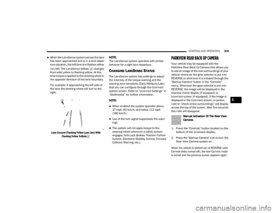
When the LaneSense system senses the lane
has been approached and is in a lane depar -
ture situation, the left lane line flashes yellow
(on/off). The LaneSense telltale changes
from solid yellow to flashing yellow. At this
time torque is applied to the steering wheel in
the opposite direction of the lane boundary.
For example: If approaching the left side of
the lane the steering wheel will turn to the
right.
Lane Crossed (Flashing Yellow Lane Line) With Flashing Yellow Telltale
NOTE:
The LaneSense system operates with similar
behavior for a right lane departure.
CHANGING LANESENSE STATUS
The LaneSense system has settings to adjust
the intensity of the torque warning and the
warning zone sensitivity (Early/Medium/Late)
that you can configure through the Uconnect
system screen. Refer to “Uconnect Settings” in
“Multimedia” for further information.
NOTE:
When enabled the system operates above
37 mph (60 km/h) and below 112 mph
(180 km/h).
Use of the turn signal suppresses the warn -
ings.
The system will not apply torque to the
steering wheel whenever a safety system
engages (Anti-Lock Brakes, Traction Control
System, Electronic Stability Control, Forward
Collision Warning, etc.).
PARKVIEW REAR BACK UP CAMERA
Your vehicle may be equipped with the
ParkView Rear Back Up Camera that allows you
to see an image of the rear surroundings of your
vehicle whenever the gear selector is put into
REVERSE or whenever it is initiated through the
"Backup Camera" button in the "Controls"
menu. Whenever the gear selector is put into
REVERSE, the image will be displayed in the
rearview mirror display (if equipped) or
Uconnect screen (if equipped). If the image is
displayed in the Uconnect screen, a caution
note to “check entire surroundings” will display
across the top of the screen. After five seconds
this note will disappear.
Manual Activation Of The Rear View
Camera:
1. Press the "Controls" button located on the bottom of the Uconnect display.
2. Press the "Backup Camera" icon to turn the Rear View Camera system on.
When the vehicle is shifted out of REVERSE (with
Camera delay turned off), the rear Camera mode
is exited and the previous screen appears again.
5
20_DJD2_OM_EN_USC_t.book Page 309
Page 321 of 568
STARTING AND OPERATING319
(Continued)
ENGINE RUNAWAY — DIESEL ENGINE
Diesel engine runaway is a rare condition
affecting diesel engines, where the engine
consumes its own lubrication oil and runs at
higher and higher RPM until it overspeeds to a
point where it destroys itself due to either
mechanical failure or engine seizure through
lack of lubrication.
REFUELING THE VEHICLE — GAS ENGINE
The fuel filler cap (gas cap) is located behind the
fuel filler door, on the left side of the vehicle.
Open the fuel door and remove the fuel filler cap
by turning it counter-clockwise.
Fuel Filler Cap
NOTE:
When removing the fuel filler cap, lay the cap
tether in the hook, located on the fuel filler door.
NOTE:
When the fuel nozzle “clicks” or shuts off, the
fuel tank is full.
WARNING!
In case of engine runaway due to flammable
fumes from fuel spills or turbocharger oil
leaks being sucked into the engine, do the
following to help avoid personal injury and/or
vehicle damage:
1. Turn the ignition switch to the OFF position.
2. Using a CO2 or dry chemical type fire
extinguisher, direct the spray from the fire
extinguisher into the grille on the driver side
so that the spray enters the engine air intake.
The inlet for the engine air intake is located
behind the drivers side headlamp and
receives air through the grille.
WARNING!
Never have any smoking materials lit in or
near the vehicle when the gas cap is
removed or the tank is being filled.
Never add fuel to the vehicle when the
engine is running.
A fire may result if gasoline is pumped into
a portable container that is inside of a
vehicle. You could be burned. Always place
gas containers on the ground while filling.
CAUTION!
Damage to the fuel system or emissions
control system could result from using an
improper fuel tank filler tube cap.
A poorly fitting fuel filler cap could let impu-
rities into the fuel system.
A poorly fitting fuel filler cap may cause the
“Malfunction Indicator Light (MIL)” to turn
on.
To avoid fuel spillage and overfilling, do not
“top off” the fuel tank after filling. When the
fuel nozzle “clicks” or shuts off, the fuel
tank is full.
WARNING! (Continued)
5
20_DJD2_OM_EN_USC_t.book Page 319
Page 333 of 568
STARTING AND OPERATING331
(Continued)
Towing Requirements — Tires
Do not attempt to tow a trailer while using a
compact spare tire.
Do not drive more than 50 mph (80 km/h) when towing while using a full size spare tire.
Proper tire inflation pressures are essential
to the safe and satisfactory operation of your
vehicle. Refer to “Tires” in “Servicing And
Maintenance” for proper tire inflation proce -
dures.
Check the trailer tires for proper tire inflation
pressures before trailer usage.
Check for signs of tire wear or visible tire
damage before towing a trailer. Refer to
“Tires” in “Servicing And Maintenance” for
the proper inspection procedure.
When replacing tires, refer to “Tires” in
“Servicing And Maintenance” for the proper
tire replacement procedures. Replacing tires
with a higher load carrying capacity will not
increase the vehicle's GVWR and GAWR
limits.
Towing Requirements — Trailer Brakes
Do not interconnect the hydraulic brake
system or vacuum system of your vehicle
with that of the trailer. This could cause inad -
equate braking and possible personal injury.
An electronically actuated trailer brake
controller is required when towing a trailer
with electronically actuated brakes. When
towing a trailer equipped with a hydraulic
surge actuated brake system, an electronic
brake controller is not required.
Trailer brakes are recommended for trailers
over 1,000 lbs (453 kg) and required for
trailers in excess of 2,000 lbs (907 kg).
When hauling cargo or towing a trailer, do
not overload your vehicle or trailer. Over -
loading can cause a loss of control, poor
performance or damage to brakes, axle,
engine, transmission, steering, suspension,
chassis structure or tires.
Safety chains must always be used
between your vehicle and trailer. Always
connect the chains to the hook retainers of
the vehicle hitch. Cross the chains under
the trailer tongue and allow enough slack
for turning corners.
Vehicles with trailers should not be parked
on a grade. When parking, apply the
parking brake on the tow vehicle. Put the
tow vehicle transmission in PARK. For
four-wheel drive vehicles, make sure the
transfer case is not in NEUTRAL. Always,
block or "chock" the trailer wheels.
GCWR must not be exceeded.
WARNING! (Continued)
Total weight must be distributed between
the tow vehicle and the trailer such that the
following four ratings are not exceeded :
GVWR
GTW
GAWR
Tongue weight rating for the trailer
hitch utilized.
WARNING! (Continued)
5
20_DJD2_OM_EN_USC_t.book Page 331
Page 335 of 568
STARTING AND OPERATING333
If a fault is detected in the trailer wiring or the
Integrated Trailer Brake Module (ITBM), the
“Trailer Brake Status Indicator Light” will flash.
GAIN Adjustment Buttons (+/-)
Pushing these buttons will adjust the brake
control power output to the trailer brakes in
0.5 increments. The GAIN setting can be
increased to a maximum of 10 or decreased to
a minimum of 0 (no trailer braking).
GAIN
The GAIN setting is used to set the trailer brake
control for the specific towing condition and
should be changed as towing conditions
change. Changes to towing conditions include
trailer load, vehicle load, road conditions and
weather.
Adjusting GAIN
NOTE:
This should only be performed in a traffic free
environment at speeds of approximately
20–25 mph (30–40 km/h).
1. Make sure the trailer brakes are in good
working condition, functioning normally
and properly adjusted. See your trailer
dealer if necessary.
2. Hook up the trailer and make the electrical connections according to the trailer
manufacturer's instructions.
3. When a trailer with electric/EOH brakes is plugged in, the trailer connected message
should appear in the instrument cluster
display (if the connection is not recognized
by the ITBM, braking functions will not be
available), the GAIN setting will illuminate
and the correct type of trailer must be
selected from the instrument cluster display
options.
4. Push the UP or DOWN button on the steering wheel until “TRAILER TOW”
appears on the screen.
5. Push the RIGHT arrow on the steering wheel to enter “TRAILER TOW”. 6. Push the UP or DOWN buttons until the
Trailer Brake Type appears on the screen.
7. Push the RIGHT arrow and then push the UP or DOWN buttons until the proper Trailer
Brake Type appears on the screen.
8. In a traffic-free environment, tow the trailer on a dry, level surface at a speed of
20–25 mph (30–40 km/h) and squeeze
the manual brake control lever completely.
9. If the trailer wheels lockup (indicated by squealing tires), reduce the GAIN setting; if
the trailer wheels turn freely, increase the
GAIN setting.
Repeat steps 8 and 9 until the GAIN setting is at
a point just below trailer wheel lockup. If towing
a heavier trailer, trailer wheel lockup may not be
attainable even with the maximum GAIN setting
of 10.
5
20_DJD2_OM_EN_USC_t.book Page 333
Page 346 of 568
344STARTING AND OPERATING
(Continued)
OFF-ROAD DRIVING TIPS
Care should be taken when attempting to climb
steep hills or driving diagonally across a hill or
slope. If natural obstacles force you to travel
diagonally up or down a hill, choose a mild angle
and keep as little side tilt as possible. Keep the
vehicle moving and make turns slowly and
cautiously.
If you must back down a hill, back straight down
using REVERSE gear. Never back down in
NEUTRAL or diagonally across the hill.
When driving over sand, mud, and other soft
terrain, shift to low gear and drive steadily.
Apply the accelerator slowly to avoid spinning
the wheels.
Do not reduce the tire pressures for this type of
driving.Driving through standing water limits your
vehicle’s braking capabilities, which
increases stopping distances. Therefore,
after driving through standing water, drive
slowly and lightly press on the brake pedal
several times to dry the brakes.
Failure to follow these warnings may result
in injuries that are serious or fatal to you,
your passengers, and others around you.
CAUTION!
Always check the depth of the standing
water before driving through it. Never drive
through standing water that is deeper than
the bottom of the tire rims mounted on the
vehicle.
Determine the condition of the road or the
path that is under water and if there are any
obstacles in the way before driving through
the standing water.
WARNING! (Continued)
Do not exceed 5 mph (8 km/h) when
driving through standing water. This will
minimize wave effects.
Driving through standing water may cause
damage to your vehicle’s drivetrain compo -
nents. Always inspect your vehicle’s fluids
(i.e., engine oil, transmission, axle, etc.) for
signs of contamination (i.e., fluid that is
milky or foamy in appearance) after driving
through standing water. Do not continue to
operate the vehicle if any fluid appears
contaminated, as this may result in further
damage. Such damage is not covered by
the New Vehicle Limited Warranty.
Getting water inside your vehicle’s engine
can cause it to lock up and stall out, and
cause serious internal damage to the
engine. Such damage is not covered by the
New Vehicle Limited Warranty.
CAUTION! (Continued)
20_DJD2_OM_EN_USC_t.book Page 344
Page 355 of 568
IN CASE OF EMERGENCY353
REPLACING EXTERIOR BULBS
Base Quad: Low Beam Headlamp, High
Beam Headlamp, Front Park And Turn — If
Equipped
Low Beam
1. Open the hood.
2. Disconnect and isolate the negative battery
cable.
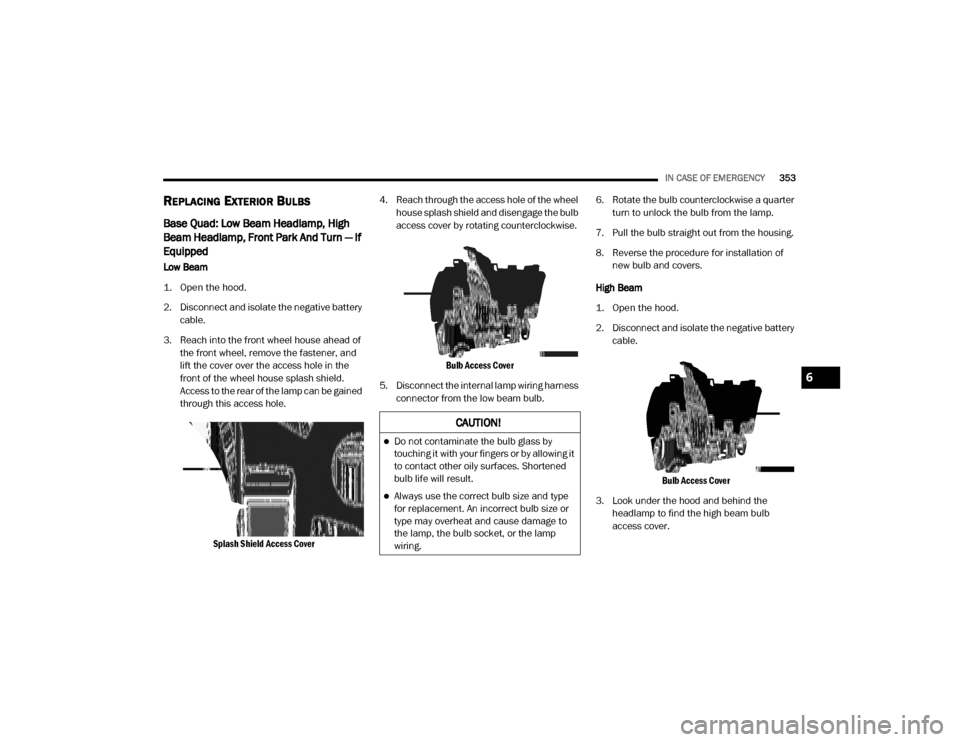
3. Reach into the front wheel house ahead of the front wheel, remove the fastener, and
lift the cover over the access hole in the
front of the wheel house splash shield.
Access to the rear of the lamp can be gained
through this access hole.
Splash Shield Access Cover
4. Reach through the access hole of the wheel
house splash shield and disengage the bulb
access cover by rotating counterclockwise.
Bulb Access Cover
5. Disconnect the internal lamp wiring harness connector from the low beam bulb. 6. Rotate the bulb counterclockwise a quarter
turn to unlock the bulb from the lamp.
7. Pull the bulb straight out from the housing.
8. Reverse the procedure for installation of new bulb and covers.
High Beam
1. Open the hood.
2. Disconnect and isolate the negative battery cable.
Bulb Access Cover
3. Look under the hood and behind the headlamp to find the high beam bulb
access cover.
CAUTION!
Do not contaminate the bulb glass by
touching it with your fingers or by allowing it
to contact other oily surfaces. Shortened
bulb life will result.
Always use the correct bulb size and type
for replacement. An incorrect bulb size or
type may overheat and cause damage to
the lamp, the bulb socket, or the lamp
wiring.
6
20_DJD2_OM_EN_USC_t.book Page 353
Page 356 of 568
354IN CASE OF EMERGENCY
4. Reach behind the headlamp and disengage
the access cover by rotating counter -
clockwise.
5. Disconnect the internal lamp wiring harness connector from the high beam bulb.
6. Rotate the bulb counterclockwise a quarter turn to unlock the bulb from the lamp.
7. Pull the bulb straight out from the housing.
8. Reverse the procedure for installation of new bulb and covers. Front Park And Turn
1. Open the hood.
2. Disconnect and isolate the negative battery
cable.
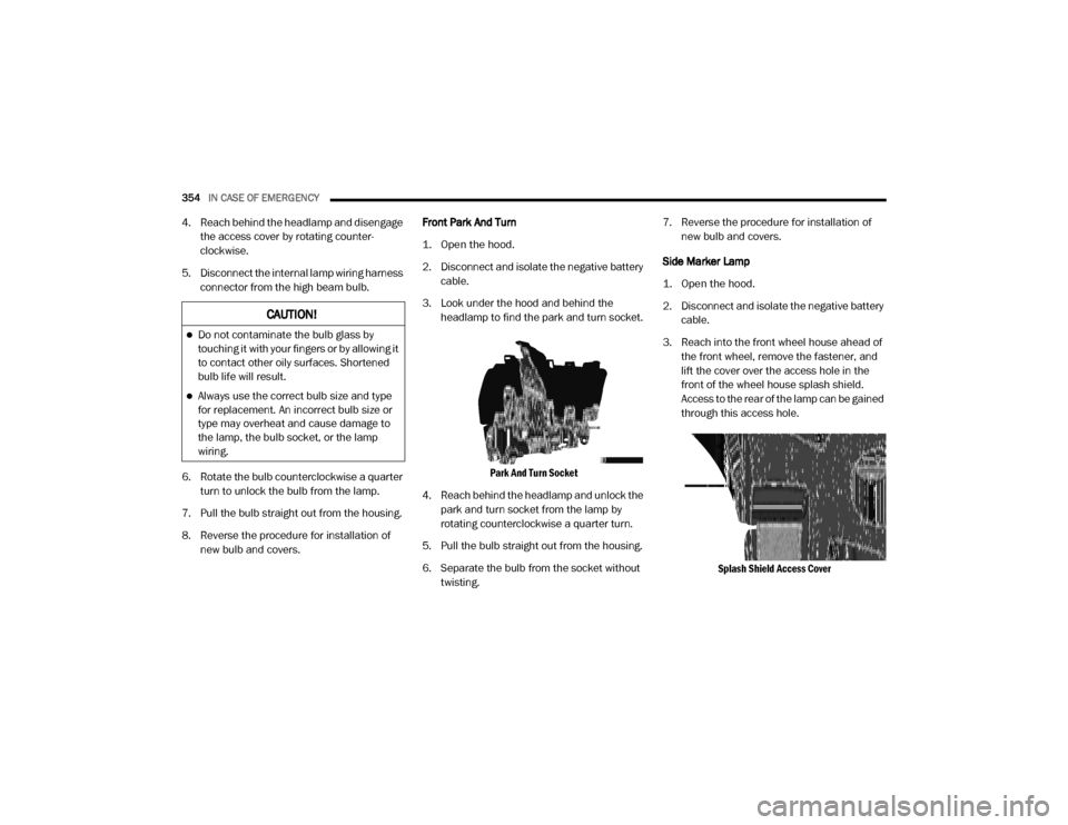
3. Look under the hood and behind the headlamp to find the park and turn socket.
Park And Turn Socket
4. Reach behind the headlamp and unlock the park and turn socket from the lamp by
rotating counterclockwise a quarter turn.
5. Pull the bulb straight out from the housing.
6. Separate the bulb from the socket without twisting. 7. Reverse the procedure for installation of
new bulb and covers.
Side Marker Lamp
1. Open the hood.
2. Disconnect and isolate the negative battery cable.
3. Reach into the front wheel house ahead of the front wheel, remove the fastener, and
lift the cover over the access hole in the
front of the wheel house splash shield.
Access to the rear of the lamp can be gained
through this access hole.
Splash Shield Access Cover
CAUTION!
Do not contaminate the bulb glass by
touching it with your fingers or by allowing it
to contact other oily surfaces. Shortened
bulb life will result.
Always use the correct bulb size and type
for replacement. An incorrect bulb size or
type may overheat and cause damage to
the lamp, the bulb socket, or the lamp
wiring.
20_DJD2_OM_EN_USC_t.book Page 354