lock Ram 3500 2020 Owner's Manual
[x] Cancel search | Manufacturer: RAM, Model Year: 2020, Model line: 3500, Model: Ram 3500 2020Pages: 568
Page 357 of 568

IN CASE OF EMERGENCY355
4. Reach through the access hole of the wheel
house splash shield and disengage the side
marker socket by rotating counterclockwise
a quarter turn.
Side Marker Socket
5. Pull the socket and bulb straight out from the housing.
6. Separate the bulb from the socket without twisting.
7. Reverse the procedure for installation of new bulb and covers.
Fog Lamps — If Equipped
Please see an authorized dealer for service on
LED and Halogen front fog lamps. Halogen
1. Reach under and behind the front bumper
to access the back of the front fog lamp
housing.
2. Disconnect the fog lamp wiring harness connector from the fog lamp bulb.
3. Rotate the bulb counterclockwise a quarter turn to unlock the bulb from the housing.
Fog Lamp Bulb
4. Pull the bulb straight out from the housing.
Rear Tail/Stop, Turn Signal And Backup
Lamps
1. Remove the two screws and push pins that pass through the bed sheet metal.
Tail Lamp Locations
CAUTION!
Do not contaminate the bulb glass by
touching it with your fingers or by allowing it
to contact other oily surfaces. Shortened bulb
life will result.
1 — Tail Lamp
2 — Screws
3 — Fasteners
6
20_DJD2_OM_EN_USC_t.book Page 355
Page 358 of 568

356IN CASE OF EMERGENCY
2. Pull the outboard side of the lamp rearward
far enough to unsnap the two receptacles
on the outboard side of the lamp housing
from the two plastic snap post retainers in
the outer box side panel.
Tail Lamp Removed
3. Disconnect the wiring harness connectors from the bulb socket.
4. Rotate the bulb socket counterclockwise a quarter turn to unlock it from the housing.
5. Pull the bulb straight out of the socket. 6. Reverse the procedure to install the bulb
and housing.
Center High Mounted Stop Lamp (CHMSL)
With Cargo Lamp
1. Remove the two screws holding the housing/lens to the body as shown.
CHMSL Mounting Screw Locations
2. Separate the connector holding the housing and wiring harness to the body.
3. Turn the desired bulb socket a quarter turn and remove the socket and bulb from
housing. 4. Pull the desired bulb straight from the
socket.
CHMSL Bulb And Socket
Outside Bulbs: Cargo Lamps
Inside Bulb: Center High Mounted Stop
Lamp
5. Reverse the procedure for installation of bulbs and housing.
CAUTION!
Do not contaminate the bulb glass by
touching it with your fingers or by allowing it
to contact other oily surfaces. Shortened bulb
life will result.
CAUTION!
Do not contaminate the bulb glass by
touching it with your fingers or by allowing it
to contact other oily surfaces. Shortened bulb
life will result.
20_DJD2_OM_EN_USC_t.book Page 356
Page 359 of 568

IN CASE OF EMERGENCY357
Cab Top Clearance Lamps — If Equipped
1. Remove the screws from the top of the
lamp.
Removing Rear Screw From Clearance Lamp
2. Rotate the bulb socket a quarter turn and pull it from the lamp assembly.
Removing Bulb Socket From Clearance Lamp
3. Pull the bulb straight from it's socket and
replace.
Rear Lamp Bar ID Marker (Dual Rear
Wheels) — If Equipped
1. Loosen the two screws and the housing to gain access to the bulb sockets.
Screw Locations
2. Turn the socket a quarter turn counter -
clockwise to access the bulb.
3. Pull the bulb straight out from the socket.
4. Reverse the procedure for installation of the bulbs and housing.
Side Marker Lamps (Dual Rear Wheels) —
If Equipped
Side Marker Lamp Locations
1. Push rearward on the side marker lamp assembly.
2. Pull the entire assembly from the fender.
3. Turn the socket a quarter turn counter -
clockwise and remove from assembly to
access the bulb.
4. Pull the bulb straight out from socket.
5. Reverse the procedure for installation of the bulbs and housing.
6
20_DJD2_OM_EN_USC_t.book Page 357
Page 361 of 568

IN CASE OF EMERGENCY359
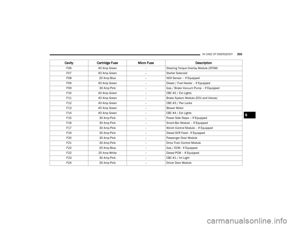
F0640 Amp Green –Steering Torque Overlay Module (STOM)
F07 40 Amp Green –Starter Solenoid
F08 20 Amp Blue –NOX Sensor – If Equipped
F09 40 Amp Green –Diesel / Fuel Heater – If Equipped
F09 30 Amp Pink –Gas / Brake Vacuum Pump – If Equipped
F10 40 Amp Green –CBC #2 / Ext Lights
F11 40 Amp Green –Brake System Module (ECU and Valves)
F12 40 Amp Green –CBC #3 / Pwr Locks
F13 40 Amp Green –Blower Motor
F14 40 Amp Green –CBC #4 / Ext Lights
F15 30 Amp Pink –Power Side Steps — If Equipped
F16 30 Amp Pink –Smart-Bar Module – If Equipped
F17 30 Amp Pink –Winch Control Module – If Equipped
F19 30 Amp Pink –Diesel SCR Feed– If Equipped
F20 30 Amp Pink –Passenger Door Module
F21 30 Amp Pink –Drive Train Control Module
F22 20 Amp Blue –Gas / ECM– If Equipped
F22 25 Amp White –Diesel PCM – If Equipped
F23 30 Amp Pink –CBC #1 / Int Light
F24 30 Amp Pink –Driver Door Module
Cavity Cartridge Fuse Micro Fuse Description
6
20_DJD2_OM_EN_USC_t.book Page 359
Page 363 of 568

IN CASE OF EMERGENCY361
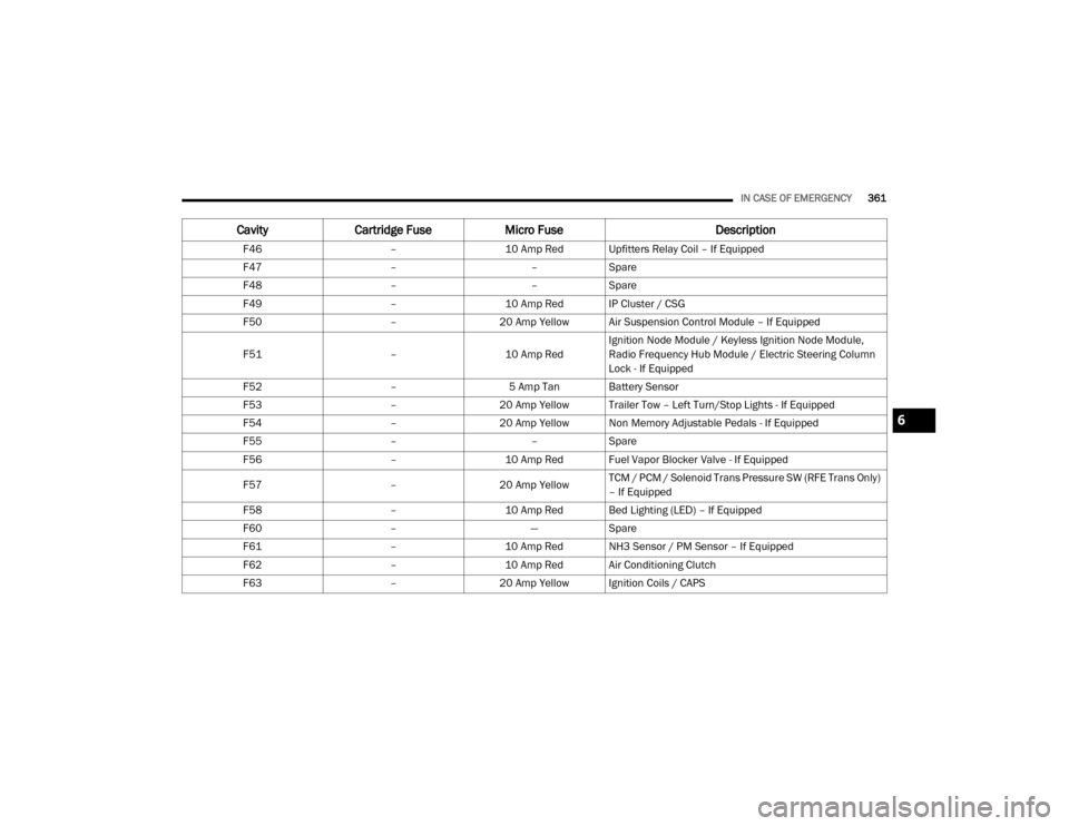
F46 –10 Amp Red Upfitters Relay Coil – If Equipped
F47 ––Spare
F48 ––Spare
F49 –10 Amp Red IP Cluster / CSG
F50 –20 Amp Yellow Air Suspension Control Module – If Equipped
F51 –10 Amp RedIgnition Node Module / Keyless Ignition Node Module,
Radio Frequency Hub Module / Electric Steering Column
Lock - If Equipped
F52 –5 Amp Tan Battery Sensor
F53 –20 Amp Yellow Trailer Tow – Left Turn/Stop Lights - If Equipped
F54 –20 Amp Yellow Non Memory Adjustable Pedals - If Equipped
F55 ––Spare
F56 –10 Amp Red Fuel Vapor Blocker Valve - If Equipped
F57 –20 Amp Yellow TCM / PCM / Solenoid Trans Pressure SW (RFE Trans Only)
– If Equipped
F58 –10 Amp Red Bed Lighting (LED) – If Equipped
F60 –—Spare
F61 –10 Amp Red NH3 Sensor / PM Sensor – If Equipped
F62 –10 Amp Red Air Conditioning Clutch
F63 –20 Amp Yellow Ignition Coils / CAPS
CavityCartridge Fuse Micro Fuse Description
6
20_DJD2_OM_EN_USC_t.book Page 361
Page 367 of 568

IN CASE OF EMERGENCY365
JACKING AND TIRE CHANGING NOTE:
If your vehicle is equipped with an air suspen -
sion system, there is a feature which allows the
automatic leveling to be disabled to assist with
changing a tire.
This feature can be activated through the Ucon -
nect system.
Refer to “Uconnect Settings” in “Multimedia”
for further information.
JACK LOCATION
The jack and tools are stored under the front
passenger seat.
REMOVAL OF JACK AND TOOLS
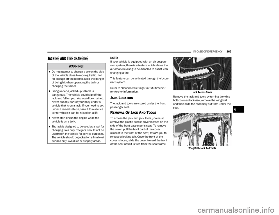
To access the jack and jack tools, you must
remove the plastic access cover located on the
side of the front passenger’s seat. To remove
the cover, pull the front part of the cover
(closest to the front of the seat) toward you to
release a locking tab. Once the front of the
cover is loose, slide the cover toward the front
of the seat until it is free from the seat frame.
Jack Access Cover
Remove the jack and tools by turning the wing
bolt counterclockwise, remove the wing bolt
and then slide the assembly out from under the
seat.
Wing Bolt/Jack And Tools
WARNING!
Do not attempt to change a tire on the side
of the vehicle close to moving traffic. Pull
far enough off the road to avoid the danger
of being hit when operating the jack or
changing the wheel.
Being under a jacked-up vehicle is
dangerous. The vehicle could slip off the
jack and fall on you. You could be crushed.
Never put any part of your body under a
vehicle that is on a jack. If you need to get
under a raised vehicle, take it to a service
center where it can be raised on a lift.
Never start or run the engine while the
vehicle is on a jack.
The jack is designed to be used as a tool for
changing tires only. The jack should not be
used to lift the vehicle for service purposes.
The vehicle should be jacked on a firm level
surface only. Avoid ice or slippery areas.
6
20_DJD2_OM_EN_USC_t.book Page 365
Page 368 of 568

366IN CASE OF EMERGENCY
(Continued)
Remove the jack and tools from the bracket
assembly. Turn the jack turn-screw
counterclockwise to release jack from bracket
assembly.
Jack And Tools Bracket AssemblyJacking Tools
There are two ways to assemble the tools:
Assembled For Spare Tire Lowering/Raising
Assembled For Spare Tire Lowering/Raising
Assembled For Jack Operation
Assembled For Jack Operation
1 — Lug Wrench
2 — Extension 2
3 — Extension 3
4 — Extension 4
CAUTION!
The lug wrench can only be attached to
extension two (2).
When attaching the tool to the winch mech -
anism be sure the large flared end opening
on extension four (4) is positioned correctly
over the winch mechanism adjusting nut.
Damage to the lug wrench, extensions and
winch mechanism may occur from
improper tool assembly.
1 — Lug Wrench
2 — Extension 2
3 — Extension 3
4 — Extension 4
5 — Jack Driver
CAUTION! (Continued)
20_DJD2_OM_EN_USC_t.book Page 366
Page 369 of 568

IN CASE OF EMERGENCY367
REMOVING THE SPARE TIRE
1. Remove the spare tire before attempting to
jack up the truck. Attach the lug wrench to
the extension tubes with the curved angle
facing away from the vehicle. Insert the
extension tube through the access hole
between the lower tailgate and the top of the
bumper and into the winch mechanism tube.
Winch Mechanism Tube Inserting The Extension Tubes Into The Access Hole
2. Rotate the lug wrench handle counter -
clockwise until the spare tire is on the
ground with enough cable slack to allow you
to pull it out from under the vehicle.
Rotating The Lug Wrench Handle
3. Pull the spare tire out from under the vehicle to gain access to the spare tire retainer.
4. Lift the spare tire with one hand to give
clearance to tilt the retainer at the end of
the cable.
Gaining Access To The Retainer
5. Pull the retainer through the center of the wheel.
Pulling The Retainer Through The Center Of The Wheel
WARNING!
After using the jack and tools, always reinstall
them in the original carrier and location.
While driving you may experience abrupt
stopping, rapid acceleration or sharp turns. A
loose jack, tools, bracket or other objects in
the vehicle may move around with force,
resulting in serious injury.
6
20_DJD2_OM_EN_USC_t.book Page 367
Page 370 of 568

368IN CASE OF EMERGENCY
(Continued)
NOTE:
The winch mechanism is designed for use with
the extension tubes only. Use of an air wrench
or other power tools is not recommended and
can damage the winch.
PREPARATIONS FOR JACKING
1. Park the vehicle on a firm, level surface. Avoid ice or slippery areas.
2. Turn on the Hazard Warning Flashers.
3. Apply the parking brake.
4. Shift the transmission into Park (P).
5. Turn the ignition OFF.
6. Block both the front and rear of the wheel diagonally opposite the jacking position. For
example, if the driver’s front wheel is being
changed, block the passenger’s rear wheel.
Wheel Blocked
NOTE:
Passengers should not remain in the vehicle
when the vehicle is being raised or lifted.
JACKING INSTRUCTIONS
WARNING!
Do not attempt to change a tire on the side of
the vehicle close to moving traffic. Pull far
enough off the road to avoid being hit when
operating the jack or changing the wheel.
WARNING!
Carefully follow these tire changing warnings
to help prevent personal injury or damage to
your vehicle:
Always park on a firm, level surface as far
from the edge of the roadway as possible
before raising the vehicle.
Turn on the Hazard Warning Flashers.
Apply the parking brake firmly and set the
transmission in PARK.
Block the wheel diagonally opposite the
wheel to be raised.
Never start or run the engine with the
vehicle on a jack.
Do not let anyone sit in the vehicle when it
is on a jack.
Do not get under the vehicle when it is on a
jack. If you need to get under a raised
vehicle, take it to a service center where it
can be raised on a lift.
Only use the jack in the positions indicated
and for lifting this vehicle during a tire
change.
If working on or near a roadway, be
extremely careful of motor traffic.
To assure that spare tires, flat or inflated,
are securely stowed, spares must be
stowed with the valve stem facing the
ground.
WARNING! (Continued)
20_DJD2_OM_EN_USC_t.book Page 368
Page 371 of 568

IN CASE OF EMERGENCY369
Jack Warning Label
Lug Wrench Adapter Shown In Jack And Tools Assembly
1. Remove the spare wheel, jack, and tools
from storage.
2. Using the lug wrench, loosen, but do not remove, the wheel nuts by turning them
counterclockwise one turn while the wheel
is still on the ground. Changing a dually tire
requires the lug wrench adapter.
NOTE:
If your vehicle is equipped with hub caps/wheel
covers they must be removed before raising the
vehicle off the ground. Refer to ”Hub Caps/
Wheel Covers — If Equipped” in this section.
Lug Wrench Adapter
Lug Wrench Adapter And Wrench
3. Placement of the jack is critical:
CAUTION!
Do not attempt to raise the vehicle by jacking
on locations other than those indicated in the
Jacking Instructions for this vehicle.
6
20_DJD2_OM_EN_USC_t.book Page 369