lock Ram 3500 2020 Repair Manual
[x] Cancel search | Manufacturer: RAM, Model Year: 2020, Model line: 3500, Model: Ram 3500 2020Pages: 568
Page 168 of 568

166SAFETY
Should this occur, you should stop as soon as
possible and inflate the tires with a low pressure
condition (those in a different color in the
instrument cluster graphic) to the vehicle’s
recommended cold placard pressure inflation
value as shown in the "Inflate to XX" message.
Once the system receives the updated tire
pressures, the system will automatically
update, the graphic display in the instrument
cluster will return to its original color, and the
“Tire Pressure Monitoring Telltale Light” will
turn off. The vehicle may need to be driven for
up to 20 minutes above 15 mph (24 km/h) in
order for the TPMS to receive this information.
NOTE:
When filling warm tires, the tire pressure may
need to be increased up to an additional 4 psi
(28 kPa) above the recommended cold placard
pressure in order to turn the Tire Pressure Moni -
toring Warning Light off.
Service TPMS Warning
If a system fault is detected, the “Tire Pressure
Monitoring Warning Light” will flash on and off
for 75 seconds and then remain on solid. In
addition, the instrument cluster will display a "SERVICE TPM SYSTEM" message for a
minimum of five seconds and then display
dashes (- -) in place of the pressure value to
indicate which sensor is not being received.
If the ignition switch is cycled, this sequence will
repeat, providing the system fault still exists. If
the system fault no longer exists, the “Tire
Pressure Monitoring Warning Light” will no
longer flash, and the "SERVICE TPM SYSTEM"
message will no longer display, and a pressure
value will display in place of the dashes. A
system fault can occur due to any of the
following:
Signal interference due to electronic devices
or driving next to facilities emitting the same
radio frequencies as the TPM sensors.
Installing aftermarket window tinting that
contains materials that may block radio wave
signals.
Accumulation of snow or ice around the
wheels or wheel housings.
Using tire chains on the vehicle.
Using wheels/tires not equipped with TPM
sensors.A system fault may occur due to an incorrect
TPM sensor location condition. When a system
fault occurs due to an incorrect TPM sensor
location, the “Tire Pressure Monitoring Warning
Light” will flash on and off for 75 seconds and
then remain on solid. The system fault will also
sound a chime. In addition, the instrument
cluster will display a “Tire Pressure Temporarily
Unavailable” message in place of the tire
pressure display screen. If the ignition switch is
cycled, this sequence will repeat, providing the
system fault still exists. If the system fault no
longer exists, the “Tire Pressure Monitoring
Warning Light” will no longer flash and the tire
pressure display screen will be displayed
showing the tire pressure values the correct
locations.
Vehicles With Non-Matching Full Size Spare Or
Compact Spare
The non-matching full size spare or compact
spare tire does not have a TPM sensor.
Therefore, the TPMS will not monitor the
pressure in the non-matching full size spare
or compact spare tire.
20_DJD2_OM_EN_USC_t.book Page 166
Page 173 of 568

SAFETY171
Operation:
The horn will chirp once when the selected
pressure is reached to let the user know
when to stop inflating or deflating the tire.
The horn will chirp three times if the tire is
over inflated or over deflated and will
continue to chirp every five seconds if the
user continues to inflate or deflate the tire.
The horn will chirp once again when enough
air is added or removed to reach proper
selected pressure level.
Tire Pressure Information System (TPIS)
3500 Series Trucks
Your vehicle may be equipped with a Tire
Pressure Information System (TPIS).
The Tire Pressure Information System (TPIS)
uses wireless technology with wheel rim
mounted electronic sensors to transmit tire
pressure levels. Sensors mounted to each
wheel as part of the valve stem transmit tire
pressure readings to the receiver module. NOTE:
It is particularly important for you to check the
tire pressure in all of the tires on your vehicle
monthly and to maintain the proper pressure.
The TPIS consists of the following components:
Receiver module
Four TPM sensors (Single Rear Wheel (SRW)
applications)
Six TPM sensors (Dual Rear Wheel (DRW)
applications)
Pressure display in the instrument cluster
The TPIS system will display all four (Single Rear
Wheel (SRW) applications) or six (Dual Rear
Wheel (DRW) applications) tire pressure values
in the instrument cluster display.
If a system fault is detected, the instrument
cluster will display a "SERVICE TPM SYSTEM"
message for a minimum of five seconds and
then display dashes (- -) in place of the pressure
value to indicate which sensor is not being
received. If the ignition switch is cycled, this sequence will
repeat, providing the system fault still exists. If
the system fault no longer exists, the "SERVICE
TPM SYSTEM" message will no longer be
displayed, and a pressure value will display in
place of the dashes. A system fault can occur
due to any of the following:
Signal interference due to electronic devices
or driving next to facilities emitting the same
radio frequencies as the TPM sensors.
Installing aftermarket window tinting that
contains materials that may block radio wave
signals.
Accumulation of snow or ice around the
wheels or wheel housings.
Using tire chains on the vehicle.
Using wheels/tires not equipped with TPM
sensors.
4
20_DJD2_OM_EN_USC_t.book Page 171
Page 176 of 568

174SAFETY
(Continued)
Seat Belt Reminder Light will turn on and
remain on until both outboard front seat belts
are buckled. The outboard front passenger seat
BeltAlert is not active when an outboard front
passenger seat is unoccupied.
BeltAlert Warning Sequence
The BeltAlert warning sequence is activated
when the vehicle is moving above a specified
vehicle speed range and the driver or outboard
front seat passenger is unbuckled (if equipped
with outboard front passenger seat BeltAlert)
(the outboard front passenger seat BeltAlert is
not active when the outboard front passenger
seat is unoccupied). The BeltAlert warning
sequence starts by blinking the Seat Belt
Reminder Light and sounding an intermittent
chime. Once the BeltAlert warning sequence
has completed, the Seat Belt Reminder Light
will remain on until the seat belts are buckled.
The BeltAlert warning sequence may repeat
based on vehicle speed until the driver and
occupied outboard front seat passenger seat
belts are buckled. The driver should instruct all
occupants to buckle their seat belts.Change Of Status
If the driver or outboard front seat passenger (if
equipped with outboard front passenger seat
BeltAlert) unbuckles their seat belt while the
vehicle is traveling, the BeltAlert warning
sequence will begin until the seat belts are
buckled again.
The outboard front passenger seat BeltAlert is
not active when the outboard front passenger
seat is unoccupied. BeltAlert may be triggered
when an animal or other items are placed on
the outboard front passenger seat or when the
seat is folded flat (if equipped). It is
recommended that pets be restrained in the
rear seat (if equipped) in pet harnesses or pet
carriers that are secured by seat belts, and
cargo is properly stowed.
BeltAlert can be activated or deactivated by an
authorized dealer. FCA US LLC does not
recommend deactivating BeltAlert.
NOTE:
If BeltAlert has been deactivated and the driver or
outboard front seat passenger (if equipped with
outboard front passenger seat BeltAlert) is
unbuckled the Seat Belt Reminder Light will turn
on and remain on until the driver and outboard
front seat passenger seat belts are buckled.
Lap/Shoulder Belts
All seating positions except the Mega Cab and
Crew Cab front center seating position have
combination lap/shoulder belts.
The seat belt webbing retractor will lock only
during very sudden stops or collisions. This
feature allows the shoulder part of the seat belt
to move freely with you under normal conditions.
However, in a collision the seat belt will lock and
reduce your risk of striking the inside of the
vehicle or being thrown out of the vehicle.
WARNING!
Relying on the air bags alone could lead to
more severe injuries in a collision. The air
bags work with your seat belt to restrain you
properly. In some collisions, the air bags
won’t deploy at all. Always wear your seat
belt even though you have air bags.
In a collision, you and your passengers can
suffer much greater injuries if you are not
properly buckled up. You can strike the inte
-
rior of your vehicle or other passengers, or
you can be thrown out of the vehicle. Always
be sure you and others in your vehicle are
buckled up properly.
20_DJD2_OM_EN_USC_t.book Page 174
Page 179 of 568
SAFETY177
6. To release the seat belt, push the red button
on the buckle. The seat belt will automat -
ically retract to its stowed position. If
necessary, slide the latch plate down the
webbing to allow the seat belt to retract
fully.
Lap/Shoulder Belt Untwisting Procedure
Use the following procedure to untwist a twisted
lap/shoulder belt.
1. Position the latch plate as close as possible to the anchor point.
2. At about 6 to 12 inches (15 to 30 cm) above the latch plate, grasp and twist the seat belt
webbing 180 degrees to create a fold that
begins immediately above the latch plate.
3. Slide the latch plate upward over the folded webbing. The folded webbing must enter
the slot at the top of the latch plate.
4. Continue to slide the latch plate up until it clears the folded webbing and the seat belt
is no longer twisted.
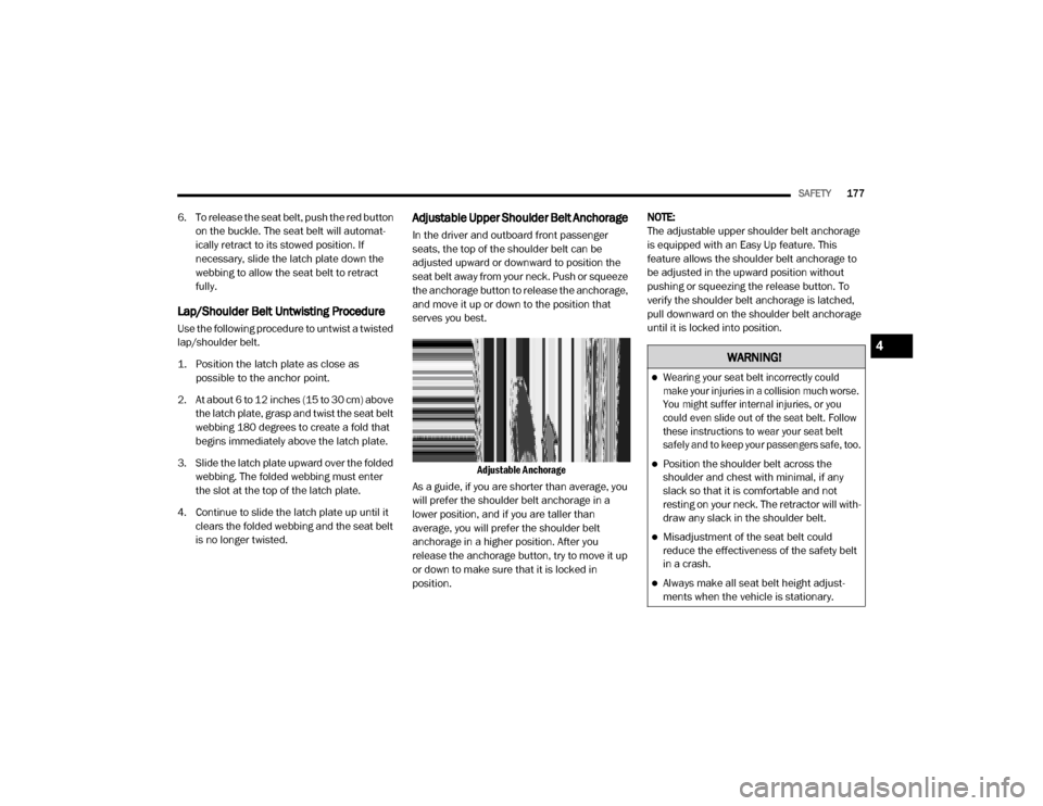
Adjustable Upper Shoulder Belt Anchorage
In the driver and outboard front passenger
seats, the top of the shoulder belt can be
adjusted upward or downward to position the
seat belt away from your neck. Push or squeeze
the anchorage button to release the anchorage,
and move it up or down to the position that
serves you best.
Adjustable Anchorage
As a guide, if you are shorter than average, you
will prefer the shoulder belt anchorage in a
lower position, and if you are taller than
average, you will prefer the shoulder belt
anchorage in a higher position. After you
release the anchorage button, try to move it up
or down to make sure that it is locked in
position. NOTE:
The adjustable upper shoulder belt anchorage
is equipped with an Easy Up feature. This
feature allows the shoulder belt anchorage to
be adjusted in the upward position without
pushing or squeezing the release button. To
verify the shoulder belt anchorage is latched,
pull downward on the shoulder belt anchorage
until it is locked into position.
WARNING!
Wearing your seat belt incorrectly could
make your injuries in a collision much worse.
You might suffer internal injuries, or you
could even slide out of the seat belt. Follow
these instructions to wear your seat belt
safely and to keep your passengers safe, too.
Position the shoulder belt across the
shoulder and chest with minimal, if any
slack so that it is comfortable and not
resting on your neck. The retractor will with
-
draw any slack in the shoulder belt.
Misadjustment of the seat belt could
reduce the effectiveness of the safety belt
in a crash.
Always make all seat belt height adjust -
ments when the vehicle is stationary.
4
20_DJD2_OM_EN_USC_t.book Page 177
Page 182 of 568
180SAFETY
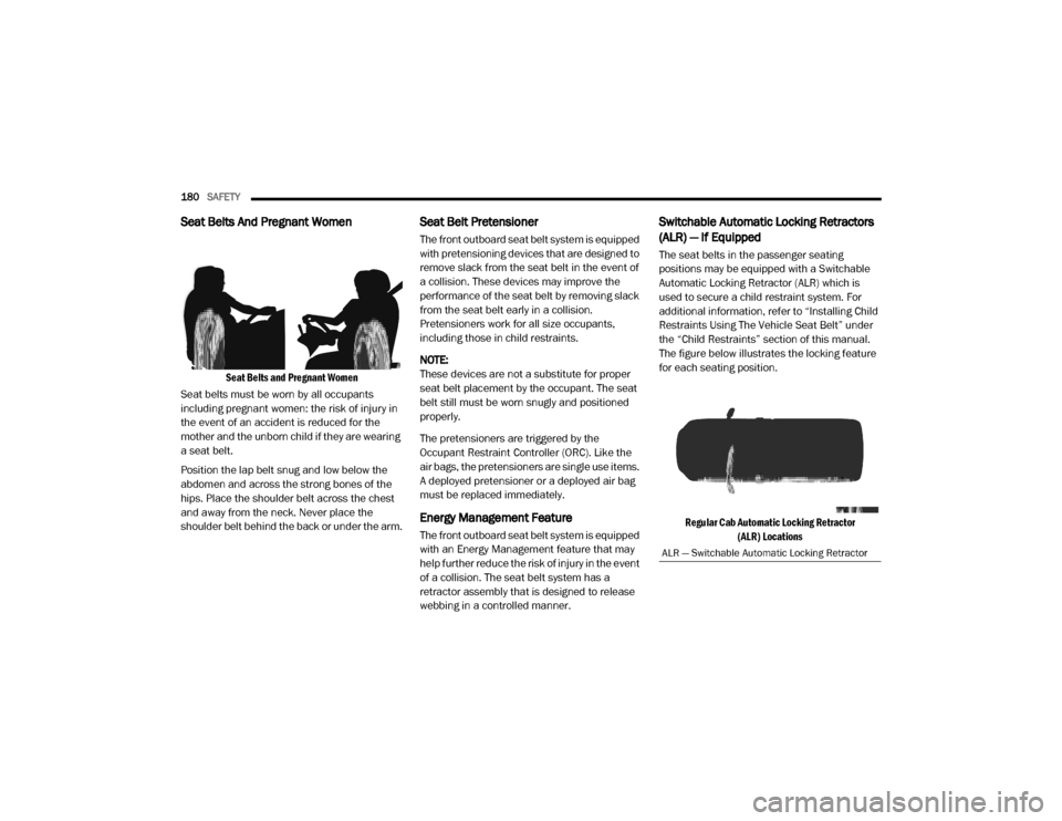
Seat Belts And Pregnant Women
Seat Belts and Pregnant Women
Seat belts must be worn by all occupants
including pregnant women: the risk of injury in
the event of an accident is reduced for the
mother and the unborn child if they are wearing
a seat belt.
Position the lap belt snug and low below the
abdomen and across the strong bones of the
hips. Place the shoulder belt across the chest
and away from the neck. Never place the
shoulder belt behind the back or under the arm.
Seat Belt Pretensioner
The front outboard seat belt system is equipped
with pretensioning devices that are designed to
remove slack from the seat belt in the event of
a collision. These devices may improve the
performance of the seat belt by removing slack
from the seat belt early in a collision.
Pretensioners work for all size occupants,
including those in child restraints.
NOTE:
These devices are not a substitute for proper
seat belt placement by the occupant. The seat
belt still must be worn snugly and positioned
properly.
The pretensioners are triggered by the
Occupant Restraint Controller (ORC). Like the
air bags, the pretensioners are single use items.
A deployed pretensioner or a deployed air bag
must be replaced immediately.
Energy Management Feature
The front outboard seat belt system is equipped
with an Energy Management feature that may
help further reduce the risk of injury in the event
of a collision. The seat belt system has a
retractor assembly that is designed to release
webbing in a controlled manner.
Switchable Automatic Locking Retractors
(ALR) — If Equipped
The seat belts in the passenger seating
positions may be equipped with a Switchable
Automatic Locking Retractor (ALR) which is
used to secure a child restraint system. For
additional information, refer to “Installing Child
Restraints Using The Vehicle Seat Belt” under
the “Child Restraints” section of this manual.
The figure below illustrates the locking feature
for each seating position.
Regular Cab Automatic Locking Retractor (ALR) Locations
ALR — Switchable Automatic Locking Retractor
20_DJD2_OM_EN_USC_t.book Page 180
Page 183 of 568
SAFETY181
(Continued)
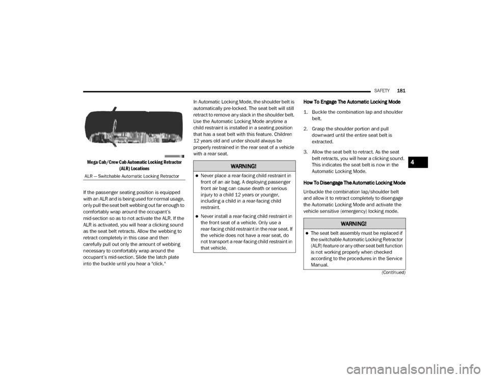
Mega Cab/Crew Cab Automatic Locking Retractor (ALR) Locations
If the passenger seating position is equipped
with an ALR and is being used for normal usage,
only pull the seat belt webbing out far enough to
comfortably wrap around the occupant’s
mid-section so as to not activate the ALR. If the
ALR is activated, you will hear a clicking sound
as the seat belt retracts. Allow the webbing to
retract completely in this case and then
carefully pull out only the amount of webbing
necessary to comfortably wrap around the
occupant’s mid-section. Slide the latch plate
into the buckle until you hear a "click." In Automatic Locking Mode, the shoulder belt is
automatically pre-locked. The seat belt will still
retract to remove any slack in the shoulder belt.
Use the Automatic Locking Mode anytime a
child restraint is installed in a seating position
that has a seat belt with this feature. Children
12 years old and under should always be
properly restrained in the rear seat of a vehicle
with a rear seat.
How To Engage The Automatic Locking Mode
1. Buckle the combination lap and shoulder
belt.
2. Grasp the shoulder portion and pull downward until the entire seat belt is
extracted.
3. Allow the seat belt to retract. As the seat belt retracts, you will hear a clicking sound.
This indicates the seat belt is now in the
Automatic Locking Mode.
How To Disengage The Automatic Locking Mode
Unbuckle the combination lap/shoulder belt
and allow it to retract completely to disengage
the Automatic Locking Mode and activate the
vehicle sensitive (emergency) locking mode.
ALR — Switchable Automatic Locking Retractor
WARNING!
Never place a rear-facing child restraint in
front of an air bag. A deploying passenger
front air bag can cause death or serious
injury to a child 12 years or younger,
including a child in a rear-facing child
restraint.
Never install a rear-facing child restraint in
the front seat of a vehicle. Only use a
rear-facing child restraint in the rear seat. If
the vehicle does not have a rear seat, do
not transport a rear-facing child restraint in
that vehicle.
WARNING!
The seat belt assembly must be replaced if
the switchable Automatic Locking Retractor
(ALR) feature or any other seat belt function
is not working properly when checked
according to the procedures in the Service
Manual.
4
20_DJD2_OM_EN_USC_t.book Page 181
Page 184 of 568
182SAFETY
SUPPLEMENTAL RESTRAINT SYSTEMS
(SRS)
Some of the safety features described in this
section may be standard equipment on some
models, or may be optional equipment on
others. If you are not sure, ask an authorized
dealer.
The air bag system must be ready to protect you
in a collision. The Occupant Restraint Controller
(ORC) monitors the internal circuits and
interconnecting wiring associated with the
electrical Air Bag System Components. Your
vehicle may be equipped with the following Air
Bag System Components:
Air Bag System Components
Occupant Restraint Controller (ORC)
Air Bag Warning Light
Steering Wheel and Column
Instrument Panel
Knee Impact Bolsters
Driver and Front Passenger Air Bags
Seat Belt Buckle Switch
Supplemental Side Air Bags
Front and Side Impact Sensors — If Equipped
Seat Belt Pretensioners
Seat Track Position Sensors
Air Bag Warning Light
The Occupant Restraint Controller
(ORC) monitors the readiness of the
electronic parts of the air bag system
whenever the ignition switch is in the
START or ON/RUN position. If the ignition switch
is in the OFF position or in the ACC position, the
air bag system is not on and the air bags will not
inflate. The ORC contains a backup power supply
system that may deploy the air bag system even
if the battery loses power or it becomes
disconnected prior to deployment.
The ORC turns on the Air Bag Warning Light in
the instrument panel for approximately four to
eight seconds for a self-check when the ignition
switch is first in the ON/RUN position. After the
self-check, the Air Bag Warning Light will turn
off. If the ORC detects a malfunction in any part
of the system, it turns on the Air Bag Warning
Light, either momentarily or continuously. A
single chime will sound to alert you if the light
comes on again after initial startup.
The ORC also includes diagnostics that will
illuminate the instrument panel Air Bag Warning
Light if a malfunction is detected that could
affect the air bag system. The diagnostics also
record the nature of the malfunction. While the
air bag system is designed to be maintenance
free, if any of the following occurs, have an
authorized dealer service the air bag system
immediately.
The Air Bag Warning Light does not come on
during the four to eight seconds when the
ignition switch is first in the ON/RUN position.
Failure to replace the seat belt assembly
could increase the risk of injury in colli
-
sions.
Do not use the Automatic Locking Mode to
restrain occupants who are wearing the
seat belt or children who are using booster
seats. The locked mode is only used to
install rear-facing or forward-facing child
restraints that have a harness for
restraining the child.
WARNING! (Continued)
20_DJD2_OM_EN_USC_t.book Page 182
Page 188 of 568
186SAFETY
(Continued)
The SABs may help to reduce the risk of
occupant injury during certain side impacts, in
addition to the injury reduction potential
provided by the seat belts and body structure.
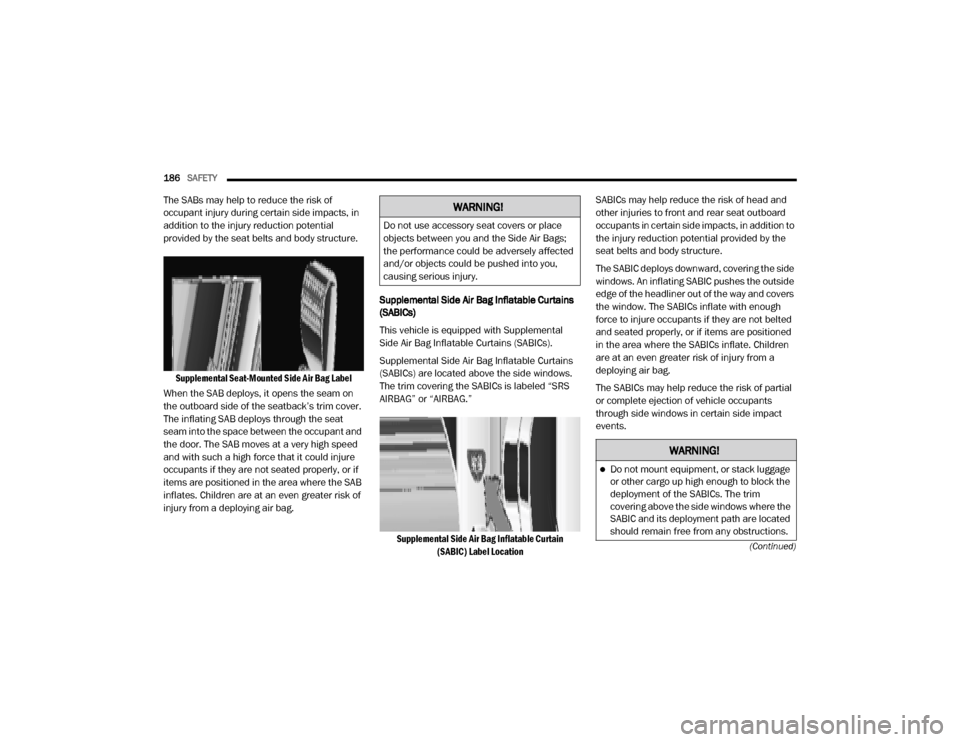
Supplemental Seat-Mounted Side Air Bag Label
When the SAB deploys, it opens the seam on
the outboard side of the seatback’s trim cover.
The inflating SAB deploys through the seat
seam into the space between the occupant and
the door. The SAB moves at a very high speed
and with such a high force that it could injure
occupants if they are not seated properly, or if
items are positioned in the area where the SAB
inflates. Children are at an even greater risk of
injury from a deploying air bag. Supplemental Side Air Bag Inflatable Curtains
(SABICs)
This vehicle is equipped with Supplemental
Side Air Bag Inflatable Curtains (SABICs).
Supplemental Side Air Bag Inflatable Curtains
(SABICs) are located above the side windows.
The trim covering the SABICs is labeled “SRS
AIRBAG” or “AIRBAG.”
Supplemental Side Air Bag Inflatable Curtain (SABIC) Label Location
SABICs may help reduce the risk of head and
other injuries to front and rear seat outboard
occupants in certain side impacts, in addition to
the injury reduction potential provided by the
seat belts and body structure.
The SABIC deploys downward, covering the side
windows. An inflating SABIC pushes the outside
edge of the headliner out of the way and covers
the window. The SABICs inflate with enough
force to injure occupants if they are not belted
and seated properly, or if items are positioned
in the area where the SABICs inflate. Children
are at an even greater risk of injury from a
deploying air bag.
The SABICs may help reduce the risk of partial
or complete ejection of vehicle occupants
through side windows in certain side impact
events.WARNING!
Do not use accessory seat covers or place
objects between you and the Side Air Bags;
the performance could be adversely affected
and/or objects could be pushed into you,
causing serious injury.
WARNING!
Do not mount equipment, or stack luggage
or other cargo up high enough to block the
deployment of the SABICs. The trim
covering above the side windows where the
SABIC and its deployment path are located
should remain free from any obstructions.
20_DJD2_OM_EN_USC_t.book Page 186
Page 191 of 568
SAFETY189
eye irritation, rinse the area with cool water.
For nose or throat irritation, move to fresh air.
If the irritation continues, see your doctor. If
these particles settle on your clothing, follow
the garment manufacturer’s instructions for
cleaning.
Do not drive your vehicle after the air bags have
deployed. If you are involved in another
collision, the air bags will not be in place to
protect you.
NOTE:
Air bag covers may not be obvious in the inte -
rior trim, but they will open during air bag
deployment.
After any collision, the vehicle should be
taken to an authorized dealer immediately.
Enhanced Accident Response System
In the event of an impact, if the communication
network remains intact, and the power remains
intact, depending on the nature of the event,
the Occupant Restraint Controller (ORC) will
determine whether to have the Enhanced
Accident Response System perform the
following functions:
Cut off fuel to the engine (if equipped)
Cut off battery power to the electric motor (if
equipped)
Flash hazard lights as long as the battery has
power
Turn on the interior lights, which remain on
as long as the battery has power or for
15 minutes from the intervention of the
Enhanced Accident Response System
Unlock the power door locks
Your vehicle may also be designed to perform
any of these other functions in response to the
Enhanced Accident Response System:
Turn off the Fuel Filter Heater, Turn off the
HVAC Blower Motor, Close the HVAC Circula -
tion Door
Cut off battery power to the:
Engine
Electric Motor (if equipped)
Electric power steering
Brake booster
Electric park brake
Automatic transmission gear selector
Horn
Front wiper
Headlamp washer pump
NOTE:
After an accident, remember to cycle the igni -
tion to the STOP (OFF/LOCK) position and
remove the key from the ignition switch to avoid
draining the battery. Carefully check the vehicle
for fuel leaks in the engine compartment and on
the ground near the engine compartment and
fuel tank before resetting the system and
starting the engine. If there are no fuel leaks or
damage to the vehicle electrical devices (e.g.
headlights) after an accident, reset the system
by following the procedure described below. If
you have any doubt, contact an authorized
dealer.
WARNING!
Deployed air bags and seat belt
pretensioners cannot protect you in another
collision. Have the air bags, seat belt
pretensioners, and the seat belt retractor
assemblies replaced by an authorized dealer
immediately. Also, have the Occupant
Restraint Controller System serviced as well.
4
20_DJD2_OM_EN_USC_t.book Page 189
Page 202 of 568
200SAFETY
some rear-facing child restraints will also be
equipped with a tether strap. The tether strap
will have a hook at the end to attach to the top
tether anchorage and a way to tighten the strap
after it is attached to the anchorage.
Center Seat LATCH
Regular Cab Or Crew Cab Full Bench Rear Seat:
No Lower Center LATCH Anchorages Available Crew Cab Split Bench Rear Seat Or Mega Cab
Rear Seat: Center LATCH Anchorages Available
If a child restraint installed in the center
position blocks the seat belt webbing or buckle
for the outboard position, do not use that
outboard position. If a child seat in the center
position blocks the outboard LATCH anchors or
seat belt, do not install a child seat in that
outboard position.
Always follow the directions of the child
restraint manufacturer when installing your
child restraint. Not all child restraint systems
will be installed as described here.
To Install A LATCH-Compatible Child
Restraint
If the selected seating position has a
Switchable Automatic Locking Retractor (ALR)
seat belt, stow the seat belt, following the
instructions below. See the section “Installing
Child Restraints Using the Vehicle Seat Belt” to
check what type of seat belt each seating
position has.
1. Loosen the adjusters on the lower straps
and on the tether strap of the child seat so
that you can more easily attach the hooks
or connectors to the vehicle anchorages.
2. Place the child seat between the lower anchorages for that seating position. If the
second row seat can be reclined, you may
recline the seat and/or raise the head
restraint (if adjustable) to get a better fit. If
the rear seat can be moved forward and
rearward in the vehicle, you may wish to
move it to its rear-most position to make
room for the child seat. You may also move
the front seat forward to allow more room
for the child seat.
WARNING!
Do not install a child restraint in the center
position using the LATCH system. This posi -
tion is not approved for installing child seats
using the LATCH attachments. You must use
the seat belt and tether anchor to install a
child seat in the center seating position.
Never use the same lower anchorage to
attach more than one child restraint. Please
refer to “To Install A LATCH-Compatible Child
Restraint” for typical installation instruc -
tions.
WARNING!
Never use the same lower anchorage to
attach more than one child restraint. Please
refer to “To Install A LATCH-Compatible Child
Restraint” for typical installation instructions.
20_DJD2_OM_EN_USC_t.book Page 200