lock Ram 3500 Chassis Cab 2020 Service Manual
[x] Cancel search | Manufacturer: RAM, Model Year: 2020, Model line: 3500 Chassis Cab, Model: Ram 3500 Chassis Cab 2020Pages: 516, PDF Size: 29.24 MB
Page 122 of 516

120(Continued)
SAFETY
SAFETY FEATURES
Anti-Lock Brake System (ABS)
The Anti-Lock Brake System (ABS) provides
increased vehicle stability and brake perfor-
mance under most braking conditions. The
system automatically prevents wheel lock, and
enhances vehicle control during braking.
The ABS performs a self-check cycle to ensure
that the ABS is working properly each time the
vehicle is started and driven. During this
self-check, you may hear a slight clicking sound
as well as some related motor noises.
ABS is activated during braking when the
system detects one or more wheels begin to
lock. Road conditions such as ice, snow, gravel,
bumps, railroad tracks, loose debris, or panic
stops may increase the likelihood of ABS activa-
tion(s). You also may experience the following when
ABS activates:
The ABS motor noise (it may continue to run
for a short time after the stop)
The clicking sound of solenoid valves
Brake pedal pulsations
A slight drop of the brake pedal at the end of
the stop
These are all normal characteristics of ABS.
WARNING!
The ABS contains sophisticated electronic
equipment that may be susceptible to inter -
ference caused by improperly installed or
high output radio transmitting equipment.
This interference can cause possible loss of
anti-lock braking capability. Installation of
such equipment should be performed by
qualified professionals.
Pumping of the Anti-Lock Brakes will
diminish their effectiveness and may lead
to a collision. Pumping makes the stopping
distance longer. Just press firmly on your
brake pedal when you need to slow down or
stop.
The ABS cannot prevent the natural laws of
physics from acting on the vehicle, nor can
it increase braking or steering efficiency
beyond that afforded by the condition of the
vehicle brakes and tires or the traction
afforded.
The ABS cannot prevent collisions,
including those resulting from excessive
speed in turns, following another vehicle
too closely, or hydroplaning.
The capabilities of an ABS equipped vehicle
must never be exploited in a reckless or
dangerous manner that could jeopardize
the user’s safety or the safety of others.
WARNING! (Continued)
2020_RAM_CHASSIS_CAB_OM_USA=GUID-6C67832B-7839-4CCF-BEFC-CDF988F949EA=1=en=.book Page 120
Page 123 of 516

SAFETY121
ABS is designed to function with the Original
Equipment Manufacturer (OEM) tires. Modifica -
tion may result in degraded ABS performance.
Anti-Lock Brake Warning Light
The yellow “Anti-Lock Brake Warning Light” will
turn on when the ignition is placed in the ON/
RUN mode and may stay on for as long as four
seconds.
If the “Anti-Lock Brake Warning Light” remains
on or comes on while driving, it indicates that
the anti-lock portion of the brake system is not
functioning and that service is required.
However, the conventional brake system will
continue to operate normally if the “Anti-Lock
Brake Warning Light” is on.
If the “Anti-Lock Brake Warning Light” is on, the
brake system should be serviced as soon as
possible to restore the benefits of anti-lock
brakes. If the “Anti-Lock Brake Warning Light”
does not come on when the ignition is placed in
the ON/RUN mode, have the light repaired as
soon as possible.
Electronic Brake Control (EBC) System
Your vehicle is equipped with an advanced Elec -
tronic Brake Control (EBC) system. This system
includes Electronic Brake Force Distribution (EBD), Anti-Lock Brake System (ABS), Brake
Assist System (BAS), Hill Start Assist (HSA),
Traction Control System (TCS), Electronic
Stability Control (ESC), and Electronic Roll Miti
-
gation (ERM). These systems work together to
enhance both vehicle stability and control in
various driving conditions.
Your vehicle may also be equipped with Trailer
Sway Control (TSC) and Hill Descent Control
(HDC).
Electronic Brake Force Distribution (EBD)
Electronic Brake Force Distribution (EBD)
manages the distribution of the braking torque
between the front and rear axles by limiting
braking pressure to the rear axle. This is done to
prevent overslip of the rear wheels to avoid
vehicle instability, and to prevent the rear axle
from entering ABS before the front axle.
Brake System Warning Light
The red “Brake System Warning Light” will turn
on when the ignition is placed in the ON/RUN
mode and may stay on for as long as four
seconds. If the “Brake System Warning Light” remains on
or comes on while driving, it indicates that the
brake system is not functioning properly and
that immediate service is required. If the “Brake
System Warning Light” does not come on when
the ignition is placed in the ON/RUN mode,
have the light repaired as soon as possible.
Brake Assist System (BAS)
The Brake Assist System (BAS) is designed to
optimize the vehicle’s braking capability during
emergency braking maneuvers. The system
detects an emergency braking situation by
sensing the rate and amount of brake applica
-
tion and then applies optimum pressure to the
brakes. This can help reduce braking distances.
The BAS complements the Anti-Lock Brake
System (ABS). Applying the brakes very quickly
results in the best BAS assistance. To receive
the benefit of the system, you must apply
continuous braking pressure during the stop-
ping sequence, (do not “pump” the brakes). Do
not reduce brake pedal pressure unless braking
is no longer desired. Once the brake pedal is
released, the BAS is deactivated.4
2020_RAM_CHASSIS_CAB_OM_USA=GUID-6C67832B-7839-4CCF-BEFC-CDF988F949EA=1=en=.book Page 121
Page 137 of 516
SAFETY135
Should this occur, you should stop as soon as
possible and inflate the tires with a low pressure
condition (those in a different color in the instru -
ment cluster graphic) to the vehicle’s recom-
mended cold placard pressure inflation value
as shown in the "Inflate to XX" message. Once
the system receives the updated tire pressures,
the system will automatically update, the
graphic display in the instrument cluster will
return to its original color, and the “Tire Pres -
sure Monitoring Warning Light” will turn off. The
vehicle may need to be driven for up to
20 minutes above 15 mph (24 km/h) in order
for the TPMS to receive this information.
NOTE:
When filling warm tires, the tire pressure may
need to be increased up to an additional 4 psi
(28 kPa) above the recommended cold placard
pressure in order to turn the Tire Pressure Moni -
toring Warning Light off.Service TPMS Warning
If a system fault is detected, the “Tire Pressure
Monitoring Warning Light” will flash on and off
for 75 seconds and then remain on solid. In
addition, the instrument cluster will display a
"SERVICE TPM SYSTEM" message for a
minimum of five seconds and then display
dashes (- -) in place of the pressure value to indi -
cate which sensor is not being received.
If the ignition switch is cycled, this sequence will
repeat, providing the system fault still exists. If
the system fault no longer exists, the “Tire Pres -
sure Monitoring Warning Light” will no longer
flash, and the "SERVICE TPM SYSTEM" message
will no longer display, and a pressure value will
display in place of the dashes. A system fault
can occur due to any of the following:
Signal interference due to electronic devices
or driving next to facilities emitting the same
radio frequencies as the TPM sensors.
Installing aftermarket window tinting that
contains materials that may block radio wave
signals.
Accumulation of snow or ice around the
wheels or wheel housings.
Using tire chains on the vehicle.
Using wheels/tires not equipped with TPM
sensors.
A system fault may occur due to an incorrect
TPM sensor location condition. When a system
fault occurs due to an incorrect TPM sensor
location, the “Tire Pressure MonitoringWarning
Light” will flash on and off for 75 seconds and
then remain on solid. The system fault will also
sound a chime. In addition, the instrument
cluster will display a “Tire Pressure Temporarily
Unavailable” message in place of the tire pres -
sure display screen. If the ignition switch is
cycled, this sequence will repeat, providing the
system fault still exists. If the system fault no
longer exists, the “Tire Pressure Monitoring Indi -
cator Light” will no longer flash and the tire pres -
sure display screen will be displayed showing
the tire pressure values in the correct locations.
4
2020_RAM_CHASSIS_CAB_OM_USA=GUID-6C67832B-7839-4CCF-BEFC-CDF988F949EA=1=en=.book Page 135
Page 142 of 516
140SAFETY
Tire Pressure Information System (TPIS)
3500/4500/5500 Series Trucks
Your vehicle may be equipped with a Tire Pres -
sure Information System (TPIS).
The Tire Pressure Information System (TPIS)
uses wireless technology with wheel rim
mounted electronic sensors to transmit tire
pressure levels. Sensors mounted to each
wheel as part of the valve stem transmit tire
pressure readings to the receiver module.
NOTE:
It is particularly important for you to check the
tire pressure in all of the tires on your vehicle
monthly and to maintain the proper pressure.
The TPIS consists of the following components:
Receiver module
Four TPM sensors (Single Rear Wheel (SRW)
applications)
Six TPM sensors (Dual Rear Wheel (DRW)
applications)
Pressure display in the instrument cluster
The TPIS system will display all four (Single Rear
Wheel (SRW) applications) or six (Dual Rear
Wheel (DRW) applications) tire pressure values
in the instrument cluster display. If a system fault is detected, the instrument
cluster will display a "SERVICE TPM SYSTEM"
message for a minimum of five seconds and
then display dashes (- -) in place of the pressure
value to indicate which sensor is not being
received.
If the ignition switch is cycled, this sequence will
repeat, providing the system fault still exists. If
the system fault no longer exists, the "SERVICE
TPM SYSTEM" message will no longer be
displayed, and a pressure value will display in
place of the dashes. A system fault can occur
due to any of the following:
Signal interference due to electronic devices
or driving next to facilities emitting the same
radio frequencies as the TPM sensors.
Installing aftermarket window tinting that
contains materials that may block radio wave
signals.
Accumulation of snow or ice around the
wheels or wheel housings.
Using tire chains on the vehicle.
Using wheels/tires not equipped with TPM
sensors.
General Information
The following regulatory statement applies to all
Radio Frequency (RF) devices equipped in this
vehicle:
This device complies with Part 15 of the FCC
Rules and with Innovation, Science and
Economic Development Canada license-exempt
RSS standard(s). Operation is subject to the
following two conditions:
1. This device may not cause harmful interfer
-
ence, and
2. This device must accept any interference received, including interference that may
cause undesired operation.
Le présent appareil est conforme aux CNR
d`Innovation, Science and Economic Develop -
ment applicables aux appareils radio exempts
de licence. L'exploitation est autorisée aux deux
conditions suivantes:
1. l'appareil ne doit pas produire de brouil -
lage, et
2. l'utilisateur de l'appareil doit accepter tout brouillage radioélectrique subi, même si le
brouillage est susceptible d'en comprom -
ettre le fonctionnement.
2020_RAM_CHASSIS_CAB_OM_USA=GUID-6C67832B-7839-4CCF-BEFC-CDF988F949EA=1=en=.book Page 140
Page 145 of 516

SAFETY143
(Continued)
Change Of Status
If the driver or outboard front seat passenger (if
equipped with outboard front passenger seat
BeltAlert) unbuckles their seat belt while the
vehicle is traveling, the BeltAlert warning
sequence will begin until the seat belts are
buckled again.
The outboard front passenger seat BeltAlert is
not active when the outboard front passenger
seat is unoccupied. BeltAlert may be triggered
when an animal or other items are placed on
the outboard front passenger seat or when the
seat is folded flat (if equipped). It is recom -
mended that pets be restrained in the rear seat
(if equipped) in pet harnesses or pet carriers
that are secured by seat belts, and cargo is
properly stowed.
BeltAlert can be activated or deactivated by an
authorized dealer. FCA US LLC does not recom -
mend deactivating BeltAlert. NOTE:
If BeltAlert has been deactivated and the driver
or outboard front seat passenger (if equipped
with outboard front passenger seat BeltAlert) is
unbuckled the Seat Belt Reminder Light will
turn on and remain on until the driver and
outboard front seat passenger seat belts are
buckled.
Lap/Shoulder Belts
All seating positions except the Crew Cab front
center seating position have combination lap/
shoulder belts.
The seat belt webbing retractor will lock only
during very sudden stops or collisions. This
feature allows the shoulder part of the seat belt
to move freely with you under normal condi
-
tions. However, in a collision the seat belt will
lock and reduce your risk of striking the inside
of the vehicle or being thrown out of the vehicle.
WARNING!
Relying on the air bags alone could lead to
more severe injuries in a collision. The air
bags work with your seat belt to restrain you
properly. In some collisions, the air bags
won’t deploy at all. Always wear your seat
belt even though you have air bags.
In a collision, you and your passengers can
suffer much greater injuries if you are not
properly buckled up. You can strike the inte -
rior of your vehicle or other passengers, or
you can be thrown out of the vehicle. Always
be sure you and others in your vehicle are
buckled up properly.
It is dangerous to ride in a cargo area,
inside or outside of a vehicle. In a collision,
people riding in these areas are more likely
to be seriously injured or killed.
Do not allow people to ride in any area of
your vehicle that is not equipped with seats
and seat belts.
4
2020_RAM_CHASSIS_CAB_OM_USA=GUID-6C67832B-7839-4CCF-BEFC-CDF988F949EA=1=en=.book Page 143
Page 148 of 516

146SAFETY
Lap/Shoulder Belt Untwisting Procedure
Use the following procedure to untwist a twisted
lap/shoulder belt.
1. Position the latch plate as close as
possible to the anchor point.
2. At about 6 to 12 inches (15 to 30 cm) above the latch plate, grasp and twist the seat belt
webbing 180 degrees to create a fold that
begins immediately above the latch plate.
3. Slide the latch plate upward over the folded webbing. The folded webbing must enter
the slot at the top of the latch plate.
4. Continue to slide the latch plate up until it clears the folded webbing and the seat belt
is no longer twisted.
Adjustable Upper Shoulder Belt Anchorage
In the driver and outboard front passenger
seats, the top of the shoulder belt can be
adjusted upward or downward to position the
seat belt away from your neck. Push or squeeze
the anchorage button to release the anchorage,
and move it up or down to the position that
serves you best.
Adjustable Anchorage
As a guide, if you are shorter than average, you
will prefer the shoulder belt anchorage in a
lower position, and if you are taller than
average, you will prefer the shoulder belt
anchorage in a higher position. After you
release the anchorage button, try to move it up
or down to make sure that it is locked in posi -
tion.
NOTE:
The adjustable upper shoulder belt anchorage
is equipped with an Easy Up feature. This
feature allows the shoulder belt anchorage to
be adjusted in the upward position without
pushing or squeezing the release button. To
verify the shoulder belt anchorage is latched,
pull downward on the shoulder belt anchorage
until it is locked into position.
WARNING!
Wearing your seat belt incorrectly could
make your injuries in a collision much
worse. You might suffer internal injuries, or
you could even slide out of the seat belt.
Follow these instructions to wear your seat
belt safely and to keep your passengers
safe, too.
Position the shoulder belt across the
shoulder and chest with minimal, if any
slack so that it is comfortable and not
resting on your neck. The retractor will with -
draw any slack in the shoulder belt.
Misadjustment of the seat belt could
reduce the effectiveness of the safety belt
in a crash.
Always make all seat belt height adjust -
ments when the vehicle is stationary.
2020_RAM_CHASSIS_CAB_OM_USA=GUID-6C67832B-7839-4CCF-BEFC-CDF988F949EA=1=en=.book Page 146
Page 151 of 516
SAFETY149
Seat Belts And Pregnant Women
Pregnant Women And Seat Belts
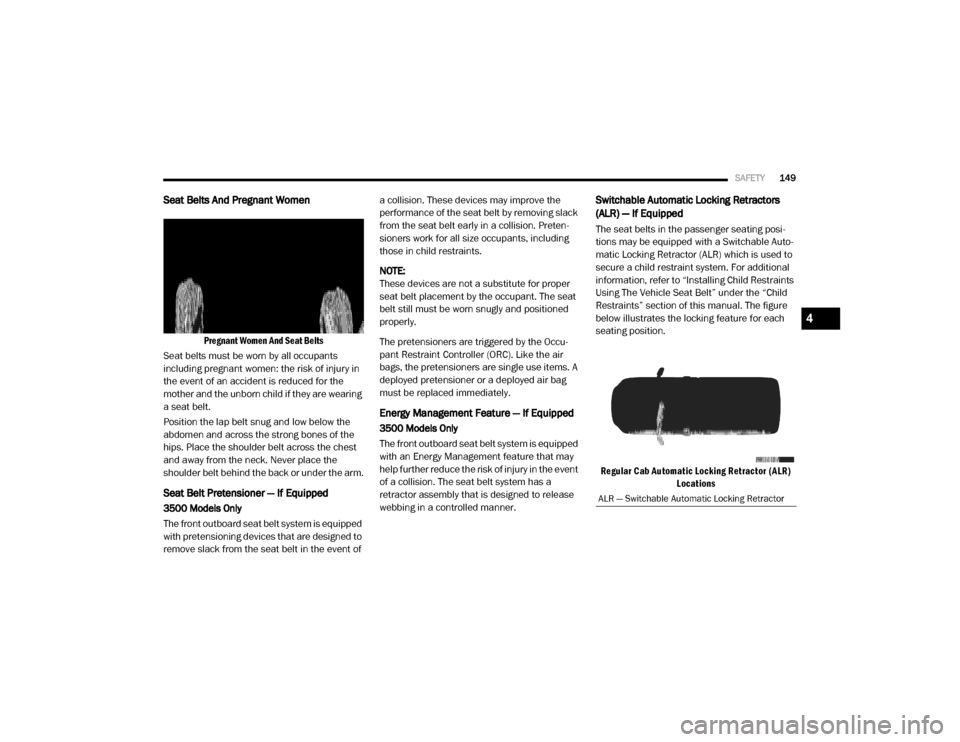
Seat belts must be worn by all occupants
including pregnant women: the risk of injury in
the event of an accident is reduced for the
mother and the unborn child if they are wearing
a seat belt.
Position the lap belt snug and low below the
abdomen and across the strong bones of the
hips. Place the shoulder belt across the chest
and away from the neck. Never place the
shoulder belt behind the back or under the arm.
Seat Belt Pretensioner — If Equipped
3500 Models Only
The front outboard seat belt system is equipped
with pretensioning devices that are designed to
remove slack from the seat belt in the event of a collision. These devices may improve the
performance of the seat belt by removing slack
from the seat belt early in a collision. Preten
-
sioners work for all size occupants, including
those in child restraints.
NOTE:
These devices are not a substitute for proper
seat belt placement by the occupant. The seat
belt still must be worn snugly and positioned
properly.
The pretensioners are triggered by the Occu -
pant Restraint Controller (ORC). Like the air
bags, the pretensioners are single use items. A
deployed pretensioner or a deployed air bag
must be replaced immediately.
Energy Management Feature — If Equipped
3500 Models Only
The front outboard seat belt system is equipped
with an Energy Management feature that may
help further reduce the risk of injury in the event
of a collision. The seat belt system has a
retractor assembly that is designed to release
webbing in a controlled manner.
Switchable Automatic Locking Retractors
(ALR) — If Equipped
The seat belts in the passenger seating posi -
tions may be equipped with a Switchable Auto -
matic Locking Retractor (ALR) which is used to
secure a child restraint system. For additional
information, refer to “Installing Child Restraints
Using The Vehicle Seat Belt” under the “Child
Restraints” section of this manual. The figure
below illustrates the locking feature for each
seating position.
Regular Cab Au tomatic Locking Retractor (A LR) Locations
ALR — Switchable Automatic Locking Retractor
4
2020_RAM_CHASSIS_CAB_OM_USA=GUID-6C67832B-7839-4CCF-BEFC-CDF988F949EA=1=en=.book Page 149
Page 152 of 516

150SAFETY
Crew Cab Automatic Locking Retractor ( ALR)
Locations
If the passenger seating position is equipped
with an ALR and is being used for normal usage,
only pull the seat belt webbing out far enough to
comfortably wrap around the occupant’s
mid-section so as to not activate the ALR. If the
ALR is activated, you will hear a clicking sound
as the seat belt retracts. Allow the webbing to
retract completely in this case and then care -
fully pull out only the amount of webbing neces -
sary to comfortably wrap around the occupant’s
mid-section. Slide the latch plate into the buckle
until you hear a "click."
In Automatic Locking Mode, the shoulder belt is
automatically pre-locked. The seat belt will still
retract to remove any slack in the shoulder belt. Use the Automatic Locking Mode anytime a
child restraint is installed in a seating position
that has a seat belt with this feature. Children
12 years old and under should always be prop
-
erly restrained in the rear seat of a vehicle with
a rear seat.
How To Engage The Automatic Locking Mode
1. Buckle the combination lap and shoulder belt.
2. Grasp the shoulder portion and pull down -
ward until the entire seat belt is extracted. 3. Allow the seat belt to retract. As the seat
belt retracts, you will hear a clicking sound.
This indicates the seat belt is now in the
Automatic Locking Mode.
How To Disengage The Automatic Locking Mode
Unbuckle the combination lap/shoulder belt
and allow it to retract completely to disengage
the Automatic Locking Mode and activate the
vehicle sensitive (emergency) locking mode.
ALR — Switchable Automatic Locking Retractor
WARNING!
Never place a rear-facing child restraint in
front of an air bag. A deploying passenger
front air bag can cause death or serious
injury to a child 12 years or younger,
including a child in a rear-facing child
restraint.
Never install a rear-facing child restraint in
the front seat of a vehicle. Only use a
rear-facing child restraint in the rear seat. If
the vehicle does not have a rear seat, do
not transport a rear-facing child restraint in
that vehicle.
WARNING!
The seat belt assembly must be replaced if
the switchable Automatic Locking Retractor
(ALR) feature or any other seat belt function
is not working properly when checked
according to the procedures in the Service
Manual.
Failure to replace the seat belt assembly
could increase the risk of injury in colli -
sions.
Do not use the Automatic Locking Mode to
restrain occupants who are wearing the
seat belt or children who are using booster
seats. The locked mode is only used to
install rear-facing or forward-facing child
restraints that have a harness for
restraining the child.
2020_RAM_CHASSIS_CAB_OM_USA=GUID-6C67832B-7839-4CCF-BEFC-CDF988F949EA=1=en=.book Page 150
Page 157 of 516
SAFETY155
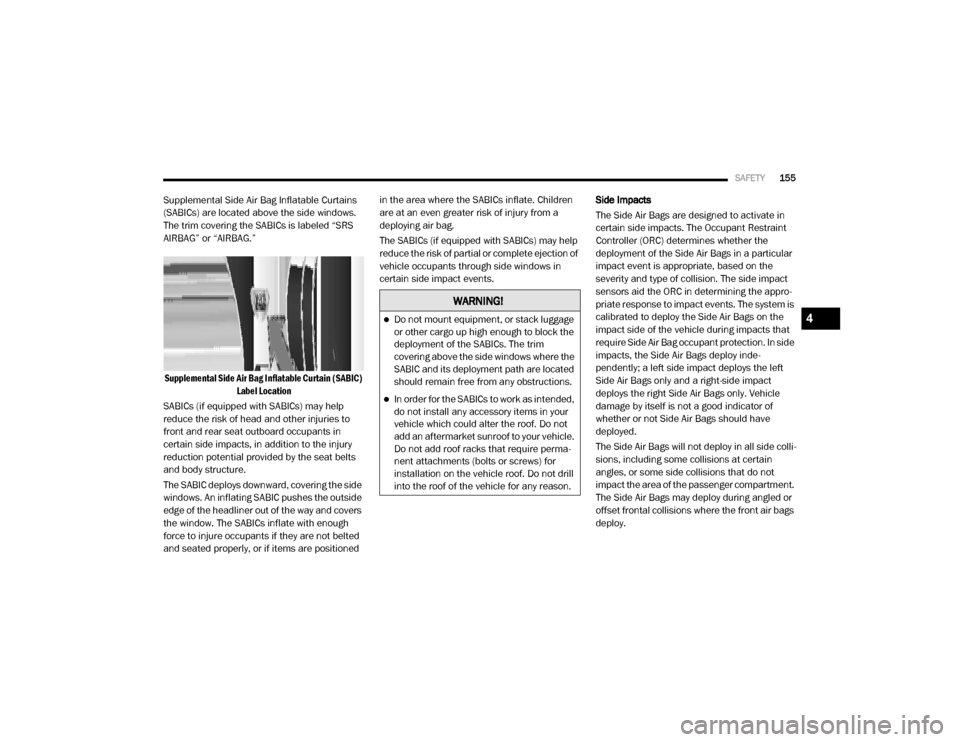
Supplemental Side Air Bag Inflatable Curtains
(SABICs) are located above the side windows.
The trim covering the SABICs is labeled “SRS
AIRBAG” or “AIRBAG.”
Supplemental Side Air Bag Inflatable Curtain (SABIC) Label Location
SABICs (if equipped with SABICs) may help
reduce the risk of head and other injuries to
front and rear seat outboard occupants in
certain side impacts, in addition to the injury
reduction potential provided by the seat belts
and body structure.
The SABIC deploys downward, covering the side
windows. An inflating SABIC pushes the outside
edge of the headliner out of the way and covers
the window. The SABICs inflate with enough
force to injure occupants if they are not belted
and seated properly, or if items are positioned in the area where the SABICs inflate. Children
are at an even greater risk of injury from a
deploying air bag.
The SABICs (if equipped with SABICs) may help
reduce the risk of partial or complete ejection of
vehicle occupants through side windows in
certain side impact events.
Side Impacts
The Side Air Bags are designed to activate in
certain side impacts. The Occupant Restraint
Controller (ORC) determines whether the
deployment of the Side Air Bags in a particular
impact event is appropriate, based on the
severity and type of collision. The side impact
sensors aid the ORC in determining the appro
-
priate response to impact events. The system is
calibrated to deploy the Side Air Bags on the
impact side of the vehicle during impacts that
require Side Air Bag occupant protection. In side
impacts, the Side Air Bags deploy inde -
pendently; a left side impact deploys the left
Side Air Bags only and a right-side impact
deploys the right Side Air Bags only. Vehicle
damage by itself is not a good indicator of
whether or not Side Air Bags should have
deployed.
The Side Air Bags will not deploy in all side colli -
sions, including some collisions at certain
angles, or some side collisions that do not
impact the area of the passenger compartment.
The Side Air Bags may deploy during angled or
offset frontal collisions where the front air bags
deploy.
WARNING!
Do not mount equipment, or stack luggage
or other cargo up high enough to block the
deployment of the SABICs. The trim
covering above the side windows where the
SABIC and its deployment path are located
should remain free from any obstructions.
In order for the SABICs to work as intended,
do not install any accessory items in your
vehicle which could alter the roof. Do not
add an aftermarket sunroof to your vehicle.
Do not add roof racks that require perma -
nent attachments (bolts or screws) for
installation on the vehicle roof. Do not drill
into the roof of the vehicle for any reason.
4
2020_RAM_CHASSIS_CAB_OM_USA=GUID-6C67832B-7839-4CCF-BEFC-CDF988F949EA=1=en=.book Page 155
Page 160 of 516
158SAFETY
(Continued)
Enhanced Accident Response System
In the event of an impact, if the communication
network remains intact, and the power remains
intact, depending on the nature of the event,
the ORC will determine whether to have the
Enhanced Accident Response System perform
the following functions:
Cut off fuel to the engine (If Equipped)
Cut off battery power to the electric motor (If
Equipped)
Flash hazard lights as long as the battery has
power
Turn on the interior lights, which remain on
as long as the battery has power or for
15 minutes from the intervention of the
Enhanced Accident Response System.
Unlock the power door locks.
Your vehicle may also be designed to perform
any of these other functions in response to the
Enhanced Accident Response System:
Turn off the Fuel Filter Heater, Turn off the
HVAC Blower Motor, Close the HVAC Circula -
tion Door
Cut off battery power to the:
Engine
Electric Motor (if equipped)
Electric power steering
Brake booster
Electric park brake
Automatic transmission gear selector
Horn
Front wiper
Headlamp washer pump
NOTE:
After an accident, remember to place the igni -
tion to the STOP (OFF/LOCK) position and
remove the key from the ignition switch to avoid
draining the battery. Carefully check the vehicle
for fuel leaks in the engine compartment and on
the ground near the engine compartment and
fuel tank before resetting the system and
starting the engine. If there are no fuel leaks or
damage to the vehicle electrical devices (e.g.
headlights) after an accident, reset the system
by following the procedure described below. If
you have any doubt, contact an authorized
dealer.
Enhanced Accident Response System Reset
Procedure
In order to reset the Enhanced Accident
Response System functions after an event, the
ignition switch must be changed from ignition
START or ON/RUN to ignition OFF. Carefully
check the vehicle for fuel leaks in the engine
compartment and on the ground near the
engine compartment and fuel tank before reset -
ting the system and starting the engine.
Maintaining Your Air Bag System
WARNING!
Modifications to any part of the air bag
system could cause it to fail when you need
it. You could be injured if the air bag system
is not there to protect you. Do not modify
the components or wiring, including adding
any kind of badges or stickers to the
steering wheel hub trim cover or the upper
passenger side of the instrument panel. Do
not modify the front bumper, vehicle body
structure, or add aftermarket side steps or
running boards.
2020_RAM_CHASSIS_CAB_OM_USA=GUID-6C67832B-7839-4CCF-BEFC-CDF988F949EA=1=en=.book Page 158