ignition Ram 4500 Chassis Cab 2018 Owner's Manual
[x] Cancel search | Manufacturer: RAM, Model Year: 2018, Model line: 4500 Chassis Cab, Model: Ram 4500 Chassis Cab 2018Pages: 298, PDF Size: 5.88 MB
Page 35 of 298
NOTE:
• The Automatic High Beam Headlamp Con-trol can be turned on or off by selecting
“ON” under “Auto High Beam” within your
Uconnect settings, as well as turning the
headlight switch to the AUTO position. Re-
fer to “Uconnect Settings” in “Multimedia”
in the Owner’s Manual at
www.mopar.com/en-us/care/owners-manual.html
(U.S. Residents) or www.owners.mopar.ca
(Canadian Residents) for further informa-
tion.
• Broken, muddy, or obstructed headlights and taillights of vehicles in the field of view
will cause headlights to remain on longer
(closer to the vehicle). Also, dirt, film, and
other obstructions on the windshield or
camera lens will cause the system to func-
tion improperly.
If the windshield or Automatic High Beam
Headlamp Control mirror is replaced, the
mirror must be re-aimed to ensure proper
performance. See a local authorized dealer.To Activate
1. The Automatic High Beams are enabled through the Uconnect system. Refer to
“Uconnect Settings” in “Multimedia” in
the Owner’s Manual at
www.mopar.com/en-us/care/owners-manual.html
(U.S. Residents) or www.owners.mopar.ca
(Canadian Residents) for further
information.
2. Turn the headlight switch to the AUTO headlight position.
3. Push the multifunction lever away from you (toward front of vehicle) to engage the
high beam mode.
NOTE:
This system will not activate until the vehicle
is at or above 20 mph (32 km/h).
To Deactivate
1. Pull the multifunction lever toward you (or rearward in vehicle) to manually deacti-
vate the system (normal operation of low
beams).
2. Push back on the multifunction lever to reactivate the system.
Automatic Headlights —
If Equipped
This system automatically turns the head-
lights on or off according to ambient light
levels. To turn the system on, rotate the
headlight switch counterclockwise to the
AUTO position. When the system is on, the
headlight time delay feature is also on. This
means the headlights will stay on for up to
90 seconds after you place the ignition into
the OFF position. The headlight time delay
can be programmed 0/30/60/90 seconds.
Refer to “Uconnect Settings” in “Multime-
dia” in the Owner’s Manual at
www.mopar.com/en-us/care/owners-manual.html
(U.S. Residents) or www.owners.mopar.ca
(Canadian Residents) for further information.
To turn the automatic system off, move the
headlight switch out of the AUTO position.
NOTE:
The engine must be running before the head-
lights will turn on in the Automatic Mode.
33
Page 38 of 298

NOTE:
This feature can be programmed through the
Uconnect system. Refer to “Uconnect Set-
tings” in “Multimedia” in the Owner’s
Manual at www.mopar.com/en-us/care/
owners-manual.html (U.S. Residents) or
www.owners.mopar.ca (Canadian Residents)
for further information.
The sensitivity of the system can be adjusted
with the multifunction lever. Wiper delay po-
sition 1 is the least sensitive, and wiper delay
position 5 is the most sensitive. Position
3 should be used for normal rain conditions.
Positions 1 and 2 can be used if the driver
desires less wiper sensitivity. Positions 4 and
5 can be used if the driver desires more
sensitivity. Place the wiper switch in the
O (off) position when not using the system.NOTE:
• The Rain Sensing feature will not operate
when the wiper switch is in the low or
high-speed position.
• The Rain Sensing feature may not function properly when ice, or dried salt water is
present on the windshield.
• Use of Rain-X or products containing wax or silicone may reduce Rain Sensing
performance.
The Rain Sensing system has protection fea-
tures for the wiper blades and arms, and will
not operate under the following conditions:
• Low Ambient Temperature — When the igni-
tion is first turned ON, the Rain Sensing
system will not operate until the wiper
switch is moved, vehicle speed is greater
than 0 mph (0 km/h), or the outside tem-
perature is greater than 32°F (0°C). •
Transmission In NEUTRAL Position — When
the ignition is ON, and the transmission is
in the NEUTRAL position, the Rain Sensing
system will not operate until the wiper
switch is moved, vehicle speed is greater
than 5 mph (8 km/h), or the gear selector is
moved out of the NEUTRAL position.
• Remote Start Mode Inhibit — On vehicles
equipped with Remote Starting system,
Rain Sensing wipers are not operational
when the vehicle is in the remote start
mode. Once the operator is in the vehicle
and has placed the ignition switch in the
RUN position, Rain Sensing wiper opera-
tion can resume, if it has been selected,
and no other inhibit conditions (mentioned
previously) exist.
GETTING TO KNOW YOUR VEHICLE
36
Page 48 of 298
• The HomeLink buttons that are located inthe overhead console or sunvisor designate
the three different HomeLink channels.
• To operate HomeLink, push and release any of the programmed HomeLink buttons.
These buttons will activate the devices they
are programmed to with each press of the
corresponding HomeLink button.
Before You Begin Programming
HomeLink
For efficient programming and accurate
transmission of the radio-frequency signal, it
is recommended that a new battery be placed
in the hand-held transmitter of the device
that is being programmed to the HomeLink
system. Make sure your hand-held transmit-
ter is programmed to activate the device you
are trying to program your HomeLink button
to.
Ensure that your vehicle is parked outside of
the garage before you begin programming.
It is recommended that you erase all the
channels of your HomeLink before you use it
for the first time. If you have any problems, or require assis-
tance, please call toll-free 1-800-355-3515
or, on the Internet at HomeLink.com for in-
formation or assistance.
Erasing All The HomeLink
Channels
To erase the channels, follow this procedure:
1. Place the ignition switch into the ON/RUN
position.
NOTE:
For vehicle’s equipped with Keyless
Enter-N-Go, place the ignition in the RUN
position with the Engine ON. Make sure to
program HomeLink with the vehicle out-
side of the garage, or with the garage door
open at all times.
2. Push and hold the two outside HomeLink buttons (I and III) for up to 20 seconds, or
until the instrument cluster display
switches from the “Clearing Channels”
message to the “Channels Cleared”
message. NOTE:
Erasing all channels should only be per-
formed when programming HomeLink for the
first time. Do not erase channels when pro-
gramming additional buttons.
Identifying Whether You Have A
Rolling Code Or Non-Rolling Code
Device
Before programming a device to one of your
HomeLink buttons, you must determine
whether the device has a rolling code or
non-rolling code.
Rolling Code Devices
To determine if your device has a rolling code,
a good indicator is its manufacturing date.
Typically, devices manufactured after
1995 have rolling codes. A device with a
rolling code will also have a “LEARN” or
“TRAIN” button located where the antenna is
attached to the device. The button may not
be immediately visible when looking at the
device. The name and color of the button may
vary slightly by manufacturer.
GETTING TO KNOW YOUR VEHICLE
46
Page 49 of 298
NOTE:
The “LEARN” or “TRAIN” button is not the
button you normally use to operate the de-
vice.
Non-rolling Code Devices
Most devices manufactured before 1995 will
not have a rolling code. These devices will
also not have a “LEARN” or “TRAIN” button.
Programming HomeLink To A
Garage Door Opener
To program any of the HomeLink buttons to
activate your garage door opener motor, fol-
low the steps below:
NOTE:
All HomeLink buttons are programmed using
this procedure. You do not need to erase all
channels when programming additional but-
tons.
1. Place the ignition switch into the ON/RUNposition. NOTE:
For vehicle’s equipped with Keyless Enter-
N-Go, place the ignition in the RUN posi-
tion with the Engine ON. Make sure to
program HomeLink with the vehicle out-
side of the garage, or with the garage door
open at all times.
2. Place the garage door opener transmitter 1 to 3 inches (3 to 8 cm) away from the
HomeLink button you wish to program,
while keeping the HomeLink indicator
light in view.
3. Push and hold the HomeLink button you want to program while you push and hold
the garage door opener transmitter button
you are trying to replicate .
4. Continue to hold both buttons until the Instrument Cluster Display changes from
“CHANNEL # TRAINING” to “CHANNEL
# TRAINED.” Once this happens, release
both buttons. NOTE:
• It may take up to 30 seconds or longer in some cases for the channel to train.
• If “DID NOT TRAIN” appears in the instrument cluster display repeat from
Step 2.
NOTE:
Make sure the garage door opener motor is
plugged in before moving on to the rolling
code/non-rolling code final steps.
Rolling Code Garage Door Opener Final Steps
NOTE:
You have 30 seconds in which to initiate
rolling code final step 2, after completing
rolling code final step 1.
1. At the garage door opener motor (in the garage), locate the “LEARN” or “TRAIN”
button. This can usually be found where
the hanging antenna wire is attached to
the garage door opener motor. Firmly push
and release the “LEARN” or “TRAIN”
button.
47
Page 50 of 298

2. Return to the vehicle and push the pro-grammed HomeLink button three times
(holding the button for two seconds each
time). The instrument cluster display will
show “CHANNEL # TRANSMIT”. If the
garage door opener motor operates, pro-
gramming is complete.
3. Push the programmed HomeLink button to confirm that the garage door opener
motor operates. If the garage door opener
motor does not operate, repeat the final
steps for the rolling code procedure.
Non-Rolling Code Garage Door Opener Final
Steps
1. Push and hold the programmed HomeLink button and observe the instru-
ment cluster display. If the instrument
cluster display shows the “CHANNEL #
TRANSMIT,” programming is complete.
2. Push the programmed HomeLink button to confirm that the garage door opener
motor operates. If the garage door opener
motor does not operate, repeat the steps
from the beginning.WARNING!
• Your motorized door or gate will openand close while you are programming
the universal transceiver. Do not pro-
gram the transceiver if people or pets are
in the path of the door or gate.
• Do not run your vehicle in a closed
garage or confined area while program-
ming the transceiver. Exhaust gas from
your vehicle contains Carbon Monoxide
(CO) which is odorless and colorless.
Carbon Monoxide is poisonous when in-
haled and can cause you and others to
be severely injured or killed.
Programming HomeLink To A
Miscellaneous Device
Refer to “Programming HomeLink To A Ga-
rage Door Opener” for the procedure on how
to program HomeLink to a miscellaneous
device, as it follows the same procedure. Be
sure to determine if the device has a rolling
code, or non-rolling code before beginning
the programming process. NOTE:
Canadian radio frequency laws require trans-
mitter signals to time-out (or quit) after sev-
eral seconds of transmission, which may not
be long enough for HomeLink to pick up the
signal during programming. Similar to this
Canadian law, some U.S. gate operators are
designed to time-out in the same manner.
The procedure may need to be preformed
multiple times to successfully pair the device
to your HomeLink buttons.
Reprogramming A Single
HomeLink Button
To reprogram a single HomeLink button that
has been previously trained, without erasing
all the channels, follow the procedure below.
Be sure to determine whether the new device
you want to program the HomeLink button to
has a Rolling Code, or Non-rolling Code.
1. Cycle the ignition to the ON/RUN
position.
GETTING TO KNOW YOUR VEHICLE
48
Page 51 of 298
NOTE:
For vehicle’s equipped with Keyless Enter-
N-Go, place the ignition in the RUN posi-
tion with the Engine ON. Make sure to
program HomeLink with the vehicle out-
side of the garage, or with the garage door
open at all times.
2. Push and hold the desired HomeLink but- ton until the instrument cluster display
shows the “CHANNEL # TRAINING” mes-
sage. Do not release the button.
3. Without releasing the button, proceed with
Step 2 in “Programming HomeLink To A
Garage Door Opener” and follow all re-
maining steps.
General Information
The following regulatory statement applies to
all Radio Frequency (RF) devices equipped in
this vehicle:
This device complies with Part 15 of the FCC
Rules and with Industry Canada license-
exempt RSS standard(s). Operation is sub-
ject to the following two conditions:
1. This device may not cause harmful inter- ference, and 2. This device must accept any interference
received, including interference that may
cause undesired operation.
NOTE:
Changes or modifications not expressly ap-
proved by the party responsible for compli-
ance could void the user’s authority to oper-
ate the equipment.
INTERNAL EQUIPMENT
Electrical Power Outlets
The auxiliary 12 Volt (13 Amp) power outlets
can provide power for in-cab accessories de-
signed for use with the standard “cigar
lighter” plug. The 12 Volt power outlets and
USB Port (Charge Only) have a cap attached
to the outlet indicating “12V DC,” together
with either a key symbol, battery symbol, or
USB symbol.
A key symbol indicates that the key must be
in the ON/RUN or ACC positions for the outlet
to provide power. The battery symbol indi-
cates that the outlet is connected to the
battery, and can provide power at all times. NOTE:
To ensure proper operation, a Mopar knob
and element must be used.
CAUTION!
• Do not exceed the maximum power of
160 Watts (13 Amps) at 12 Volts. If the
160 Watts (13 Amps) power rating is
exceeded, the fuse protecting the sys-
tem will need to be replaced.
• Power outlets are designed for accessory
plugs only. Do not insert any other object
in the power outlets as this will damage
the outlet and blow the fuse. Improper
use of the power outlet can cause dam-
age not covered by your New Vehicle
Limited Warranty.
49
Page 53 of 298

CAUTION!
quickly. Only use these intermittently
and with greater caution.
• After the use of high power draw acces-
sories, or long periods of the vehicle not
being started (with accessories still
plugged in), the vehicle must be driven a
sufficient length of time to allow the
generator to recharge the vehicle's bat-
tery.
Power Inverter — If Equipped
A 115 or 230 Volt (150 Watts Maximum)
outlet is located on the center stack of the
instrument panel, to the right of the radio.
This outlet can power cellular phones, elec-
tronics and other low power devices requiring
power up to 150 Watts. Certain high-end
video game consoles will exceed this power
limit, as will most power tools. The power inverter is designed with built-in
overload protection. If the power rating of
150 Watts is exceeded, the power inverter
will automatically shut down. Once the elec-
trical device has been removed from the out-
let the inverter should automatically reset.
To turn on the power outlet, simply plug in the
device. The outlet automatically turns off
when the device is unplugged.
NOTE:
• The Power Inverter will only turn on if the
ignition is in the ACC or ON/RUN position
• Due to built-in overload protection, the power inverter will shut down if the power
rating is exceeded.
WARNING!
To avoid serious injury or death:
• Do not insert any objects into the
receptacles.
• Do not touch with wet hands.
• Close the lid when not in use.
• If this outlet is mishandled, it may cause
an electric shock and failure.
Power Inverter
51
Page 56 of 298
INSTRUMENT CLUSTER DISPLAY
Your vehicle may be equipped with an instru-
ment cluster display, which offers useful in-
formation to the driver. With the ignition in
the STOP/OFF mode, opening/closing of a
door will activate the display for viewing, and
display the total miles, or kilometers, in the
odometer. Your instrument cluster display is
designed to display important information
about your vehicle’s systems and features.
Using a driver interactive display located on
the instrument panel, your instrument clus-
ter display can show you how systems are
working and give you warnings when they are
not. The steering wheel mounted controls
allow you to scroll through the main menus
and submenus. You can access the specific
information you want and make selections
and adjustments.
Instrument Cluster Display
Controls
The instrument cluster display features a
driver-interactive display that is located in
the instrument cluster.
The instrument cluster display menu items
may consist of the following:
• Speedometer
• Vehicle Info
• Fuel Economy Info
• Trip A
• Trip B
• Audio
• Trailer Tow
• Stored Messages
• Screen Setup
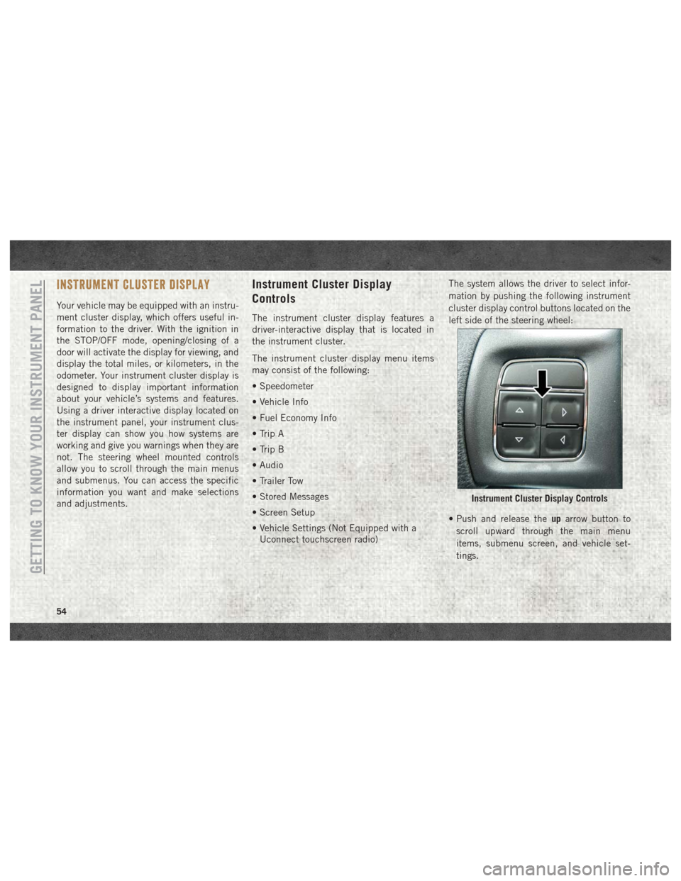
• Vehicle Settings (Not Equipped with aUconnect touchscreen radio) The system allows the driver to select infor-
mation by pushing the following instrument
cluster display control buttons located on the
left side of the steering wheel:
• Push and release the
uparrow button to
scroll upward through the main menu
items, submenu screen, and vehicle set-
tings.
Instrument Cluster Display Controls
GETTING TO KNOW YOUR INSTRUMENT PANEL
54
Page 61 of 298
under demanding hot or high altitude condi-
tions. If the instrument cluster display dis-
plays the message “Active Airbox Service
Required See Dealer”, vehicle performance
may be reduced until service is performed by
an authorized RAM dealer.
Oil Life Reset
Your vehicle is equipped with an engine oil
change indicator system. The “Oil Change
Required” message will display in the instru-
ment cluster display after a single chime has
sounded, to indicate the next scheduled oil
change interval. The engine oil change indi-
cator system is duty cycle based, which
means the engine oil change interval may
fluctuate, dependent upon your personal
driving style.
NOTE:
Use the steering wheel instrument cluster
display controls for the following proce-
dure(s).Vehicles Equipped With Passive Entry
1. Without pushing the brake pedal, push
the ENGINE START/STOP button and
place the ignition to the ON/RUN position
(do not start the engine).
2. Push and release the downarrow button to
scroll downward through the main menu
to “Vehicle Info.”
3. Push and release the rightarrow button to
access the ”Vehicle Info” screen, then
scroll up or down to select “Oil Life.”
4. Push and hold the rightarrow button to
select “Reset”.
5. Push and release the downarrow button to
select “Yes,” then push and release the
right arrow button to select reset of the Oil
Life to 100%.
6. Push and release the uparrow button to
exit the instrument cluster display screen. Vehicles Not Equipped With Passive Entry
1. Without pushing the brake pedal, cycle
the ignition to the ON/RUN position (do
not start the engine).
2. Push and release the downarrow button to
scroll downward through the main menu
to “Vehicle Info.”
3. Push and release the rightarrow button to
access the “Vehicle Info” screen then
scroll up or down to select “Oil Life.”
4. Push and hold the rightarrow button to
select “YES” by pushing the rightarrow
then push and release the rightarrow
button to select reset of the Oil Life to
100%.
5. Push and release the uparrow button to
exit the instrument cluster display screen.
NOTE:
If the indicator message illuminates when
you start the vehicle, the Oil Life indicator
system did not reset. If necessary, repeat this
procedure.
59
Page 63 of 298
WARNING LIGHTS AND MESSAGES
Red Warning Lights
— Seat Belt Reminder Warning Light
This light indicates when the driver or pas-
senger seat belt is unbuckled. When the
ignition is first placed in the ON/RUN or
ACC/ON/RUN position and if the driver’s seat
belt is unbuckled, a chime will sound and the
light will turn on. When driving, if the driver
or front passenger seat belt remains unbuck-
led, the Seat Belt Reminder Light will flash or
remain on continuously and a chime will
sound. Refer to “Occupant Restraints Sys-
tems” in “Safety” for further information.
— Air Bag Warning Light
This light indicates a fault with the air bag,
and will turn on for four to eight seconds as a
bulb check when the ignition is placed in the
ON/RUN or ACC/ON/RUN position. This light
will illuminate with a single chime when a
fault with the air bag has been detected, it
will stay on until the fault is cleared. If thelight is either not on during startup, stays on,
or turns on while driving, have the system
inspected at an authorized dealer as soon as
possible.
— Brake Warning Light
This light monitors various brake functions,
including brake fluid level and parking brake
application. If the brake light turns on it may
indicate that the parking brake is applied,
that the brake fluid level is low, or that there
is a problem with the anti-lock brake system
reservoir.
If the light remains on when the parking
brake has been disengaged, and the fluid
level is at the full mark on the master cylinder
reservoir, it indicates a possible brake hy-
draulic system malfunction or that a problem
with the Brake Booster has been detected by
the Anti-Lock Brake System (ABS) / Elec-
tronic Stability Control (ESC) system. In this
case, the light will remain on until the condi-
tion has been corrected. If the problem is
related to the brake booster, the ABS pump
will run when applying the brake, and a brake
pedal pulsation may be felt during each stop.The dual brake system provides a reserve
braking capacity in the event of a failure to a
portion of the hydraulic system. A leak in
either half of the dual brake system is indi-
cated by the Brake Warning Light, which will
turn on when the brake fluid level in the
master cylinder has dropped below a speci-
fied level.
The light will remain on until the cause is
corrected.
NOTE:
The light may flash momentarily during sharp
cornering maneuvers, which change fluid
level conditions. The vehicle should have
service performed, and the brake fluid level
checked.
If brake failure is indicated, immediate repair
is necessary.
WARNING!
Driving a vehicle with the red brake light
on is dangerous. Part of the brake system
may have failed. It will take longer to stop
the vehicle. You could have a collision.
61