key Ram 4500 Chassis Cab 2018 Owner's Manual
[x] Cancel search | Manufacturer: RAM, Model Year: 2018, Model line: 4500 Chassis Cab, Model: Ram 4500 Chassis Cab 2018Pages: 298, PDF Size: 5.88 MB
Page 22 of 298
To Unlock From The Passenger Side:
With a valid Passive Entry key fob within 5 ft
(1.5 m) of the passenger door handle, grab
the front passenger door handle to unlock all
doors automatically. The interior door panel
lock knob will raise when the door is un-
locked.
NOTE:
All doors will unlock when the front passen-
ger door handle is grabbed regardless of the
driver’s door unlock preference setting (“Un-
lock Driver Door 1st Press” or “Unlock All
Doors 1st Press”).
Preventing Inadvertent Locking Of Passive Entry
Key Fob In Vehicle:
To minimize the possibility of unintentionally
locking a Passive Entry key fob inside your
vehicle, the Passive Entry system is equipped
with an automatic door unlock feature which
will function if the ignition switch is in the
OFF position.
If one of the vehicle doors is open and the
door panel switch is used to lock the vehicle,
once all open doors have been closed the
vehicle checks the inside and outside of thevehicle for any valid Passive Entry key fobs. If
one of the vehicle's Passive Entry key fobs is
detected inside the vehicle, and no other
valid Passive Entry key fobs are detected
outside the vehicle, the Passive Entry System
automatically unlocks all vehicle doors and
chirps the horn three times (on the third
attempt ALL doors will lock and the Passive
Entry key fob can be locked in the vehicle).
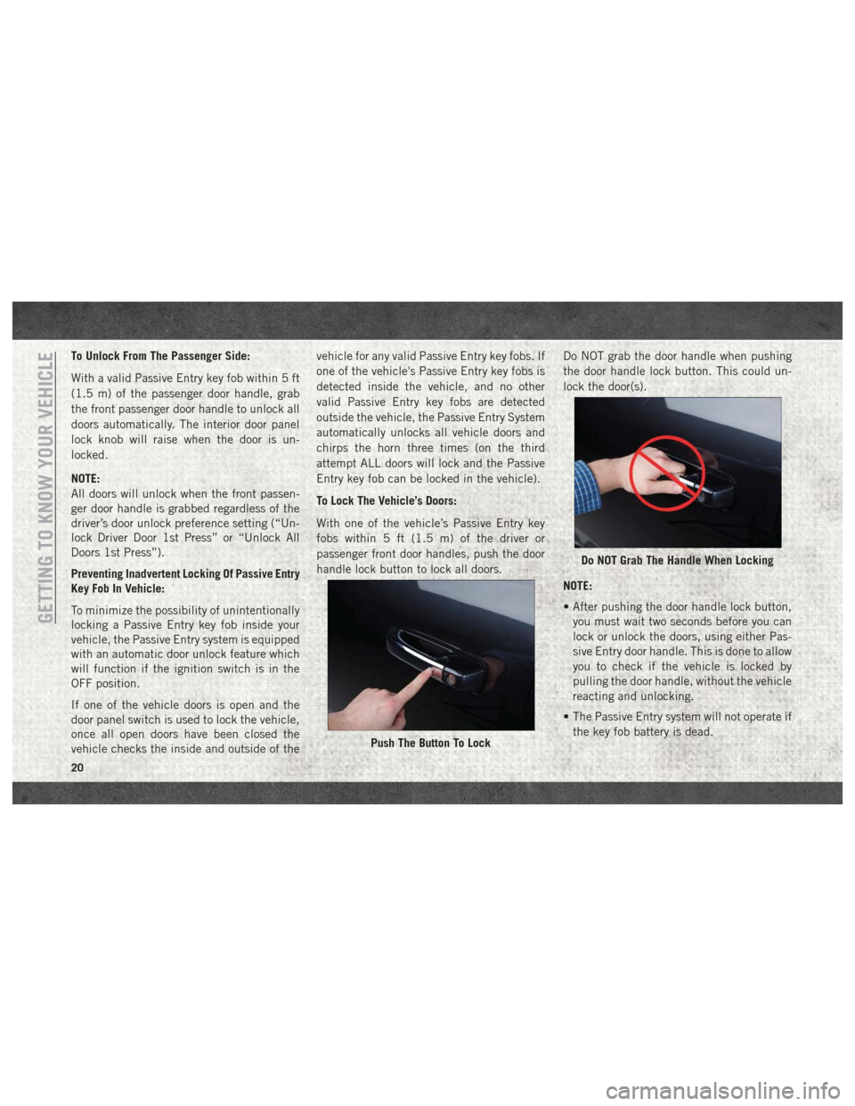
To Lock The Vehicle’s Doors:
With one of the vehicle’s Passive Entry key
fobs within 5 ft (1.5 m) of the driver or
passenger front door handles, push the door
handle lock button to lock all doors.
Do NOT grab the door handle when pushing
the door handle lock button. This could un-
lock the door(s).
NOTE:
• After pushing the door handle lock button,
you must wait two seconds before you can
lock or unlock the doors, using either Pas-
sive Entry door handle. This is done to allow
you to check if the vehicle is locked by
pulling the door handle, without the vehicle
reacting and unlocking.
• The Passive Entry system will not operate if the key fob battery is dead.
Push The Button To Lock
Do NOT Grab The Handle When Locking
GETTING TO KNOW YOUR VEHICLE
20
Page 23 of 298
The vehicle doors can also be locked by using
the key fob lock button or the lock button
located on the vehicle’s interior door panel.
General Information
The following regulatory statement applies to
all radio frequency (RF) devices equipped in
this vehicle:
This device complies with Part 15 of the FCC
Rules and with Industry Canada license-
exempt RSS standard(s). Operation is sub-
ject to the following two conditions:
1. This device may not cause harmful inter-ference, and
2. This device must accept any interference received, including interference that may
cause undesired operation.
NOTE:
Changes or modifications not expressly ap-
proved by the party responsible for compli-
ance could void the user’s authority to oper-
ate the equipment.
SEATS
Seats are a part of the Occupant Restraint
System of the vehicle.
WARNING!
• It is dangerous to ride in a cargo area, inside or outside of a vehicle. In a colli-
sion, people riding in these areas are
more likely to be seriously injured or
killed.
• Do not allow people to ride in any area of
your vehicle that is not equipped with
seats and seat belts. In a collision,
people riding in these areas are more
likely to be seriously injured or killed.
• Be sure everyone in your vehicle is in a
seat and using a seat belt properly.
Driver Memory Seat — If Equipped
This feature allows the driver to store up to
two different memory profiles for easy recall
through a memory switch. Each memory pro-
file contains desired position settings for the
driver’s seat, side mirrors, adjustable pedals
(if equipped) and a set of desired radio sta- tion presets. Your remote keyless entry key
fob can also be programmed to recall the
same positions when the unlock button is
pushed.
NOTE:
Your vehicle is equipped with two key fobs,
one key fob can be linked to memory position
1 and the other key fob can be linked to
memory position 2.
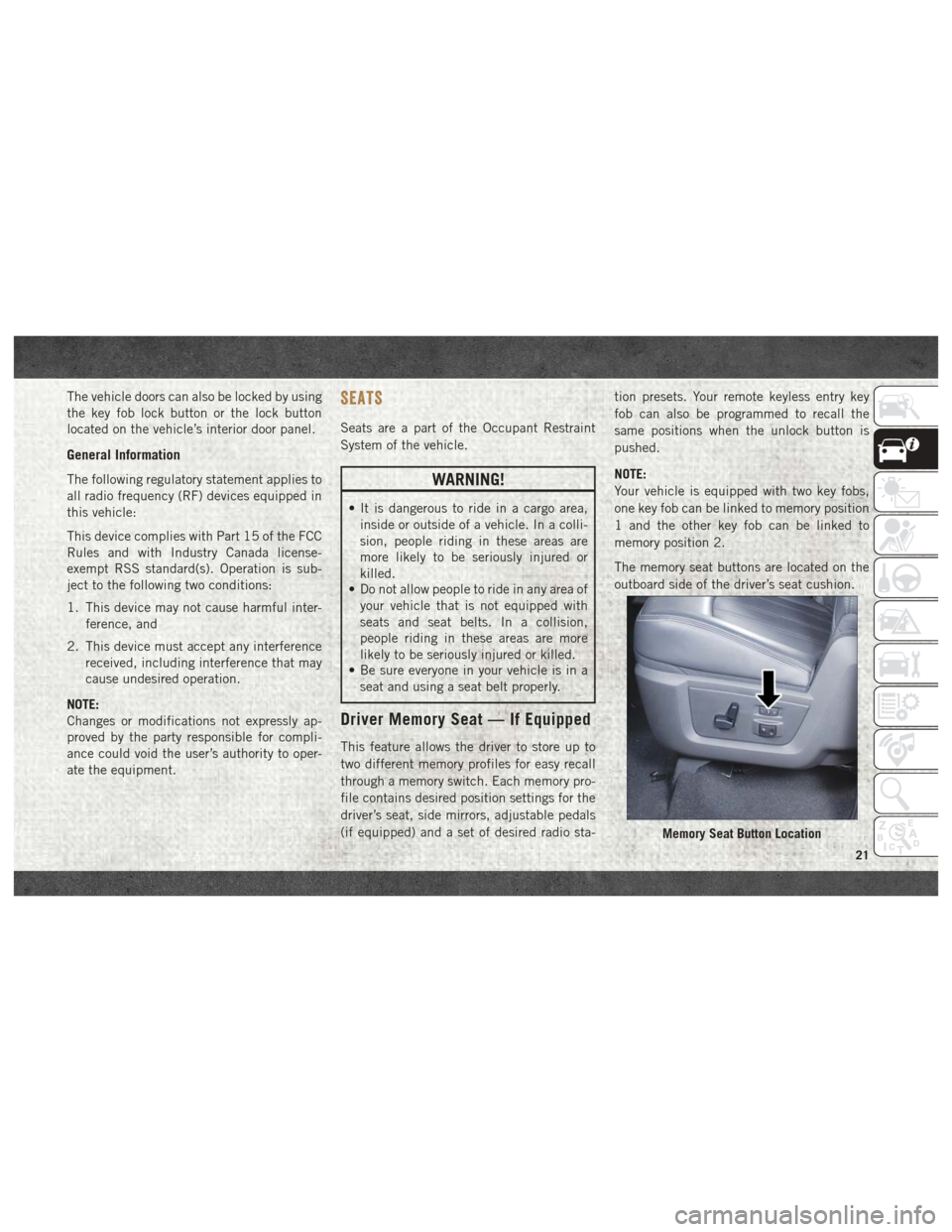
The memory seat buttons are located on the
outboard side of the driver’s seat cushion.
Memory Seat Button Location
21
Page 24 of 298
Programming The Memory Feature
To create a new memory profile, perform the
following:
1. Cycle the vehicle’s ignition to the ON/RUN position (do not start the engine).
2. Adjust all memory profile settings to de- sired preferences (i.e., driver’s seat, out-
side mirrors and radio station presets).
3. Push and release the set (S) button on the memory switch.
4. Within five seconds, push and release either of the memory buttons (1) or (2).
The instrument cluster display will show
which memory position has been set.
NOTE:
• Memory profiles can be set without the vehicle in PARK, but the vehicle must be in
PARK to recall a memory profile.
• To set a memory profile to your key fob, refer to “Linking And Unlinking The Re-
mote Keyless Entry Key Fob To Memory” in
this section.
Linking And Unlinking The Remote Keyless
Entry Key Fob To Memory
Your key fobs can be programmed to recall
one of two pre-programmed memory profiles
by pushing the unlock button on the key fob.
NOTE:
Before programming your key fobs to memory
the feature has to be selected.
• If your vehicle is equipped with a touch-screen, you must select the “Memory To
Fob” feature through the Uconnect system.
Refer to “Uconnect Settings” in “Multimedia”
in the Owner’s Manual at
www.mopar.com/
en-us/care/owners-manual.html (U.S.
Residents) or www.owners.mopar.ca
(Canadian Residents) for further information.
• If your vehicle is not equipped with a touch- screen, you must select the “Key Fob
Linked To Memory” feature through the
instrument cluster display. Refer to “In-
strument Cluster Display” in “Getting To
Know Your Instrument Panel” in the Own-
er’s Manual at www.mopar.com/en-us/
care/owners-manual.html (U.S. Residents)
or www.owners.mopar.ca (Canadian
Residents) for further information. To program your key fobs, perform the follow-
ing:
1. Cycle the vehicle’s ignition to the OFF
position.
2. Select desired memory profile (1) or (2).
NOTE:
If a memory profile has not already been
set, refer to "Programming The Memory
Feature" for instructions on how to set a
memory profile.
3. Once the profile has been recalled, push and release the set (S) button on the
memory switch, then push and release
button (1) or (2) accordingly. “Memory
Profile Set” (1 or 2) will display in the
instrument cluster display.
4. Push and release the lock button on the key fob within 10 seconds.
NOTE:
Your key fobs can be unlinked to your memory
settings by pushing the set (S) button, and
within 10 seconds, followed by pushing the
unlock button on the key fob.GETTING TO KNOW YOUR VEHICLE
22
Page 25 of 298
Memory Position Recall
NOTE:
• For vehicles equipped with an automatictransmission, the vehicle speed must be
lower than 5 mph to recall memory posi-
tions. If a recall is attempted when the
vehicle speed is greater than 5 mph, a
message will be displayed in the instru-
ment cluster display.
• For vehicles equipped with a manual trans- mission, the vehicle speed must be at
0 mph (0 km/h) to recall memory positions.
If a recall is attempted with the vehicle
speed above 0 mph (0 km/h), a message
will appear in the instrument cluster
display.
Driver One Memory Position Recall
• To recall the memory settings for driver one using the memory switch, push memory
button (1) on the memory switch.
• To recall the memory settings for driver one using the key fob, push the unlock button
on the key fob linked to memory position 1. Driver Two Memory Position Recall
• To recall the memory setting for driver two
using the memory switch, push memory
button (2) on the memory switch.
• To recall the memory settings for driver two using the key fob, push the unlock button
on the key fob linked to memory position 2.
A recall can be cancelled by pushing any of
the memory buttons during a recall (S, 1, or
2). When a recall is cancelled, the driver's
seat and the power pedals (if equipped) stop
moving. A delay of one second will occur
before another recall can be selected.
Easy Entry/Exit Seat
This feature provides automatic driver’s seat
positioning to enhance driver mobility when
entering and exiting the vehicle.
The distance the driver’s seat moves depends
on where you have the driver’s seat positioned
when you remove the key fob from the igni-
tion (or change the ignition to OFF, for ve-
hicles equipped with Keyless Enter-N-Go). • When you remove the key fob from the
ignition (or change the ignition to OFF, for
vehicles equipped with Keyless Enter-N-
Go), the driver’s seat will move about
2.4 inches (60 mm) rearward if the driver’s
seat position is greater than or equal to
2.7 inches (67.7 mm) forward of the rear
stop. The seat will return to its previously
set position when you place the ignition
into the ACC or RUN position.
• When you remove the key fob from the ignition (or change the ignition to OFF, for
vehicles equipped with Keyless Enter-N-
Go), the driver’s seat will move to a position
0.3 inches (7.7 mm) forward of the rear
stop if the driver’s seat position is between
0.9 inches and 2.7 inches (22.7 mm and
67.7 mm) forward of the rear stop. The seat
will return to its previously set position
when you place the ignition to the ACC or
RUN position.
• The Easy Entry/Easy Exit feature is disabled when the driver’s seat position is less than
0.9 inches (22.7 mm) forward of the rear
stop. At this position, there is no benefit to
the driver by moving the seat for Easy Exit
or Easy Entry.
23
Page 32 of 298
• For vehicles equipped with Driver MemorySeat, you can use your remote keyless entry
key fob or the memory switch on the driver’s
door trim panel to return the adjustable
pedals to pre-programmed positions. Refer
to “Driver Memory Seat” in “Getting To
Know Your Vehicle” for further information.
WARNING!
Do not adjust the pedals while the vehicle
is moving. You could lose control and have
an accident. Always adjust the pedals
while the vehicle is parked.
CAUTION!
Do not place any article under the adjust-
able pedals or impede its ability to move,
as it may cause damage to the pedal con-
trols. Pedal travel may become limited if
movement is stopped by an obstruction in
the adjustable pedal's path.
MIRRORS
Power Folding Outside Mirrors For
Standard And Trailer Tow —
If Equipped
If equipped with power folding mirrors, they
can be electrically folded rearward and un-
folded into the drive position.
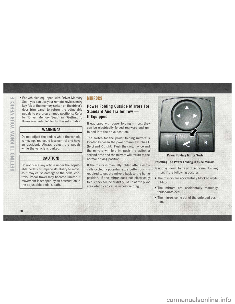
The switch for the power folding mirrors is
located between the power mirror switches L
(left) and R (right). Push the switch once and
the mirrors will fold in, push the switch a
second time and the mirrors will return to the
normal driving position.
If the mirror is manually folded after electri-
cally cycled, a potential extra button push is
required to get the mirrors back to the home
position. If the mirror does not electrically
fold, check for ice or dirt build up at the pivot
area which can cause excessive drag. Resetting The Power Folding Outside Mirrors
You may need to reset the power folding
mirrors if the following occurs:
• The mirrors are accidentally blocked while
folding.
• The mirrors are accidentally manually folded/unfolded.
• The mirrors come out of the unfolded posi- tion.
Power Folding Mirror Switch
GETTING TO KNOW YOUR VEHICLE
30
Page 36 of 298
Parking Lights And Panel Lights
To turn on the parking lights and instrument
panel lights, rotate the headlight switch
clockwise. To turn off the parking lights,
rotate the headlight switch back to the O (off)
position.
Headlights On With Wipers
(Available With Automatic
Headlights Only)
When this feature is active, the headlights
will turn on approximately 10 seconds after
the wipers are turned on if the headlight
switch is placed in the AUTO position. In
addition, the headlights will turn off when the
wipers are turned off, if they were turned on
by this feature.NOTE:
This feature can be programmed through the
Uconnect system. Refer to “Uconnect Set-
tings” in “Multimedia” in the Owner’s
Manual at www.mopar.com/en-us/care/
owners-manual.html (U.S. Residents) or
www.owners.mopar.ca (Canadian Residents)
for further information.
Turn Signals
Move the multifunction lever up or down and
the arrows on each side of the instrument
cluster display will flash to show proper op-
eration of the front and rear turn signal lights.
NOTE:
If either light remains on and does not flash,
or there is a very fast flash rate, check for a
defective outside light bulb. If an indicator
fails to light when the lever is moved, it would
suggest that the indicator bulb is defective.
Lane Change Assist —
If Equipped
Tap the lever up or down once, without mov-
ing beyond the detent, and the turn signal
(right or left) will flash three times then
automatically turn off.
Cargo Light
The cargo light is turned on by pushing on the
cargo light button.
The cargo light will also turn on for approxi-
mately 60 seconds when the unlock button
on a key fob is pushed, as part of the Illumi-
nated Entry feature.
WINDSHIELD WIPERS AND WASHERS
Windshield Wipers
The wipers and washers are operated by a
switch in the multifunction lever. Turn the
end of the lever to select the desired wiper
speed.
GETTING TO KNOW YOUR VEHICLE
34
Page 48 of 298
• The HomeLink buttons that are located inthe overhead console or sunvisor designate
the three different HomeLink channels.
• To operate HomeLink, push and release any of the programmed HomeLink buttons.
These buttons will activate the devices they
are programmed to with each press of the
corresponding HomeLink button.
Before You Begin Programming
HomeLink
For efficient programming and accurate
transmission of the radio-frequency signal, it
is recommended that a new battery be placed
in the hand-held transmitter of the device
that is being programmed to the HomeLink
system. Make sure your hand-held transmit-
ter is programmed to activate the device you
are trying to program your HomeLink button
to.
Ensure that your vehicle is parked outside of
the garage before you begin programming.
It is recommended that you erase all the
channels of your HomeLink before you use it
for the first time. If you have any problems, or require assis-
tance, please call toll-free 1-800-355-3515
or, on the Internet at HomeLink.com for in-
formation or assistance.
Erasing All The HomeLink
Channels
To erase the channels, follow this procedure:
1. Place the ignition switch into the ON/RUN
position.
NOTE:
For vehicle’s equipped with Keyless
Enter-N-Go, place the ignition in the RUN
position with the Engine ON. Make sure to
program HomeLink with the vehicle out-
side of the garage, or with the garage door
open at all times.
2. Push and hold the two outside HomeLink buttons (I and III) for up to 20 seconds, or
until the instrument cluster display
switches from the “Clearing Channels”
message to the “Channels Cleared”
message. NOTE:
Erasing all channels should only be per-
formed when programming HomeLink for the
first time. Do not erase channels when pro-
gramming additional buttons.
Identifying Whether You Have A
Rolling Code Or Non-Rolling Code
Device
Before programming a device to one of your
HomeLink buttons, you must determine
whether the device has a rolling code or
non-rolling code.
Rolling Code Devices
To determine if your device has a rolling code,
a good indicator is its manufacturing date.
Typically, devices manufactured after
1995 have rolling codes. A device with a
rolling code will also have a “LEARN” or
“TRAIN” button located where the antenna is
attached to the device. The button may not
be immediately visible when looking at the
device. The name and color of the button may
vary slightly by manufacturer.
GETTING TO KNOW YOUR VEHICLE
46
Page 49 of 298
NOTE:
The “LEARN” or “TRAIN” button is not the
button you normally use to operate the de-
vice.
Non-rolling Code Devices
Most devices manufactured before 1995 will
not have a rolling code. These devices will
also not have a “LEARN” or “TRAIN” button.
Programming HomeLink To A
Garage Door Opener
To program any of the HomeLink buttons to
activate your garage door opener motor, fol-
low the steps below:
NOTE:
All HomeLink buttons are programmed using
this procedure. You do not need to erase all
channels when programming additional but-
tons.
1. Place the ignition switch into the ON/RUNposition. NOTE:
For vehicle’s equipped with Keyless Enter-
N-Go, place the ignition in the RUN posi-
tion with the Engine ON. Make sure to
program HomeLink with the vehicle out-
side of the garage, or with the garage door
open at all times.
2. Place the garage door opener transmitter 1 to 3 inches (3 to 8 cm) away from the
HomeLink button you wish to program,
while keeping the HomeLink indicator
light in view.
3. Push and hold the HomeLink button you want to program while you push and hold
the garage door opener transmitter button
you are trying to replicate .
4. Continue to hold both buttons until the Instrument Cluster Display changes from
“CHANNEL # TRAINING” to “CHANNEL
# TRAINED.” Once this happens, release
both buttons. NOTE:
• It may take up to 30 seconds or longer in some cases for the channel to train.
• If “DID NOT TRAIN” appears in the instrument cluster display repeat from
Step 2.
NOTE:
Make sure the garage door opener motor is
plugged in before moving on to the rolling
code/non-rolling code final steps.
Rolling Code Garage Door Opener Final Steps
NOTE:
You have 30 seconds in which to initiate
rolling code final step 2, after completing
rolling code final step 1.
1. At the garage door opener motor (in the garage), locate the “LEARN” or “TRAIN”
button. This can usually be found where
the hanging antenna wire is attached to
the garage door opener motor. Firmly push
and release the “LEARN” or “TRAIN”
button.
47
Page 51 of 298
NOTE:
For vehicle’s equipped with Keyless Enter-
N-Go, place the ignition in the RUN posi-
tion with the Engine ON. Make sure to
program HomeLink with the vehicle out-
side of the garage, or with the garage door
open at all times.
2. Push and hold the desired HomeLink but- ton until the instrument cluster display
shows the “CHANNEL # TRAINING” mes-
sage. Do not release the button.
3. Without releasing the button, proceed with
Step 2 in “Programming HomeLink To A
Garage Door Opener” and follow all re-
maining steps.
General Information
The following regulatory statement applies to
all Radio Frequency (RF) devices equipped in
this vehicle:
This device complies with Part 15 of the FCC
Rules and with Industry Canada license-
exempt RSS standard(s). Operation is sub-
ject to the following two conditions:
1. This device may not cause harmful inter- ference, and 2. This device must accept any interference
received, including interference that may
cause undesired operation.
NOTE:
Changes or modifications not expressly ap-
proved by the party responsible for compli-
ance could void the user’s authority to oper-
ate the equipment.
INTERNAL EQUIPMENT
Electrical Power Outlets
The auxiliary 12 Volt (13 Amp) power outlets
can provide power for in-cab accessories de-
signed for use with the standard “cigar
lighter” plug. The 12 Volt power outlets and
USB Port (Charge Only) have a cap attached
to the outlet indicating “12V DC,” together
with either a key symbol, battery symbol, or
USB symbol.
A key symbol indicates that the key must be
in the ON/RUN or ACC positions for the outlet
to provide power. The battery symbol indi-
cates that the outlet is connected to the
battery, and can provide power at all times. NOTE:
To ensure proper operation, a Mopar knob
and element must be used.
CAUTION!
• Do not exceed the maximum power of
160 Watts (13 Amps) at 12 Volts. If the
160 Watts (13 Amps) power rating is
exceeded, the fuse protecting the sys-
tem will need to be replaced.
• Power outlets are designed for accessory
plugs only. Do not insert any other object
in the power outlets as this will damage
the outlet and blow the fuse. Improper
use of the power outlet can cause dam-
age not covered by your New Vehicle
Limited Warranty.
49
Page 62 of 298
Instrument Cluster Display Programmable Features
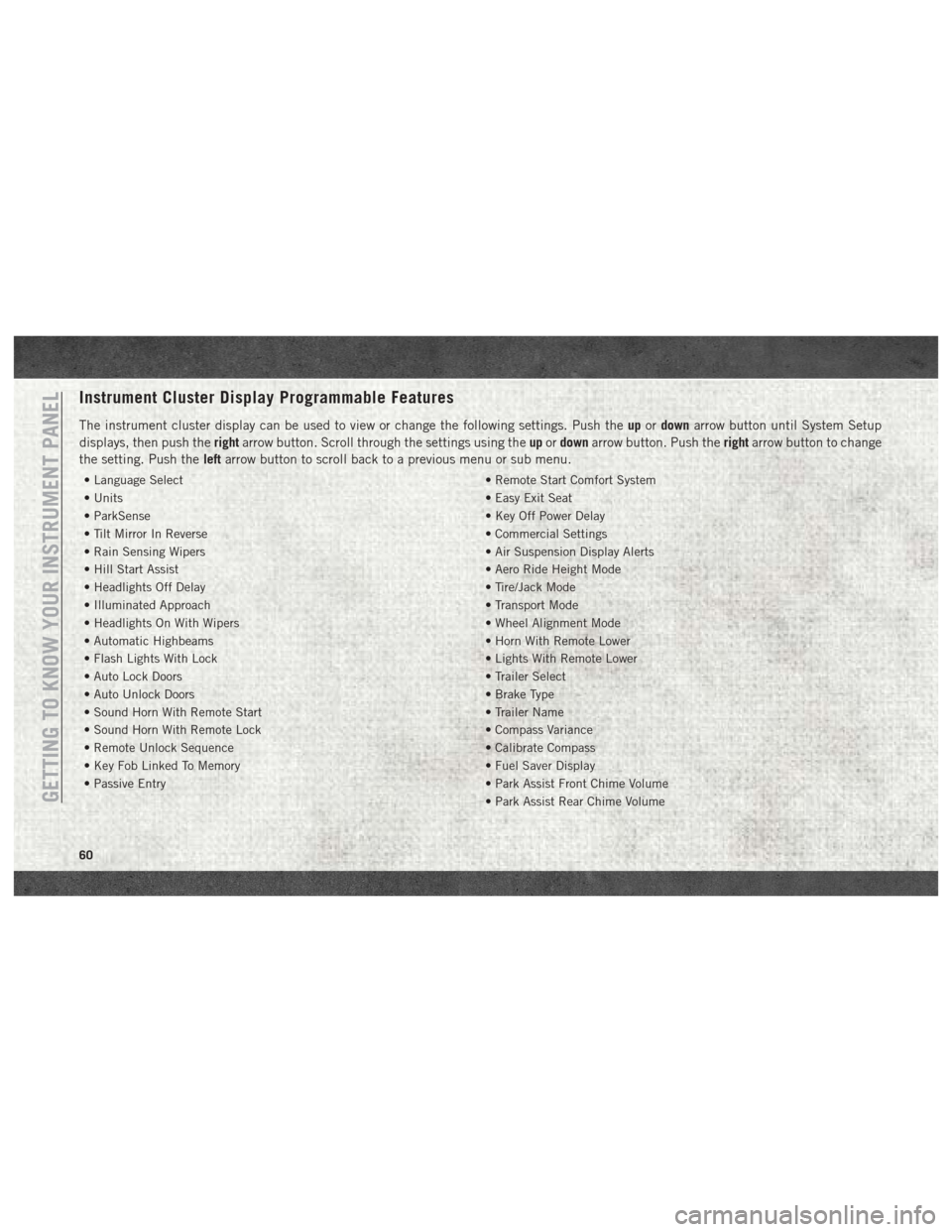
The instrument cluster display can be used to view or change the following settings. Push theupordown arrow button until System Setup
displays, then push the rightarrow button. Scroll through the settings using the upordown arrow button. Push the rightarrow button to change
the setting. Push the leftarrow button to scroll back to a previous menu or sub menu.
• Language Select • Remote Start Comfort System
• Units • Easy Exit Seat
• ParkSense • Key Off Power Delay
• Tilt Mirror In Reverse • Commercial Settings
• Rain Sensing Wipers • Air Suspension Display Alerts
• Hill Start Assist • Aero Ride Height Mode
• Headlights Off Delay • Tire/Jack Mode
• Illuminated Approach • Transport Mode
• Headlights On With Wipers • Wheel Alignment Mode
• Automatic Highbeams • Horn With Remote Lower
• Flash Lights With Lock • Lights With Remote Lower
• Auto Lock Doors • Trailer Select
• Auto Unlock Doors • Brake Type
• Sound Horn With Remote Start • Trailer Name
• Sound Horn With Remote Lock • Compass Variance
• Remote Unlock Sequence • Calibrate Compass
• Key Fob Linked To Memory • Fuel Saver Display
• Passive Entry • Park Assist Front Chime Volume
• Park Assist Rear Chime Volume
GETTING TO KNOW YOUR INSTRUMENT PANEL
60