fuel Ram 4500 Chassis Cab 2018 Owner's Manual
[x] Cancel search | Manufacturer: RAM, Model Year: 2018, Model line: 4500 Chassis Cab, Model: Ram 4500 Chassis Cab 2018Pages: 298, PDF Size: 5.88 MB
Page 140 of 298

NOTE:
If snow, ice, mud, or any foreign substance
builds up on the camera lens, clean the lens,
rinse with water, and dry with a soft cloth. Do
not cover the lens.
Turning Rear View Camera Image On:
1. Press the "Controls" button located on thebottom of the Uconnect display.
2. Press the "Backup Camera" button
to turn the Rear View Camera system on.
NOTE:
Once initiated by the "Backup Camera" but-
ton, the Rear View Camera image may be
deactivated by pressing the "X" button on the
touchscreen. On deactivation, the previous
selected screen will appear.
REFUELING THE VEHICLE — GAS
CAUTION!
• Damage to the fuel system or emissions control system could result from using
an improper fuel tank filler tube cap
(fuel filler cap). A poorly fitting cap
could let impurities into the fuel system.
Also, a poorly-fitted aftermarket cap can
cause the MIL (Malfunction Indicator
Light) to illuminate due to fuel vapors
escaping from the system.
• A poorly fitting fuel filler cap may cause
the MIL to turn on.
• To avoid fuel spillage and overfilling, do
not “top off” the fuel tank after filling.
NOTE:
When the fuel nozzle “clicks” or shuts off the
fuel tank is full.
WARNING!
• Never have any smoking materials lit in or near the vehicle when the gas cap is
removed or the tank is being filled.
• Never add fuel to the vehicle when the
engine is running. This is in violation of
most state and federal fire regulations
and may cause the MIL to turn on.
NOTE:
Tighten the gas cap ¼ turn until you hear one
click. This is an indication that the cap is
properly tightened.
If the gas cap is not tightened properly, the
Malfunction Indicator Light will come on. Be
sure the gas cap is tightened every time the
vehicle is refueled.
WARNING!
A fire may result if gasoline is pumped into a
portable container that is inside of a vehicle.
You could be burned. Always place gas con-
tainers on the ground while filling.
STARTING AND OPERATING
138
Page 141 of 298

Materials Added To Fuel
Designated TOP TIER
Detergent Gasoline
contains a higher level
of detergents to further
aide in minimizing en-
gine and fuel system
deposits. When avail-
able, the usage of Top
Tier Detergent gasoline is recommended.
Visit www.toptiergas.com for a list of TOP
TIER Detergent Gasoline Retailers.
Indiscriminate use of fuel system cleaning
agents should be avoided. Many of these
materials intended for gum and varnish re-
moval may contain active solvents or similar
ingredients. These can harm fuel system gas-
ket and diaphragm materials.
REFUELING THE VEHICLE — DIESEL
CHASSIS CAB MODELS
CAUTION!
To avoid fuel spillage and overfilling, do
not “top off” the fuel tank after filling.
NOTE:
• When the fuel nozzle “clicks” or shuts off, the fuel tank is full.
• Tighten the fuel filler cap until you hear a “clicking” sound. This is an indication that
the fuel filler cap is properly tightened.
• Make sure that the fuel filler cap is tight- ened each time the vehicle is refueled.
WARNING!
A fire may result if gasoline is pumped into
a portable container that is inside of a
vehicle. You could be burned. Always
place gas containers on the ground while
filling.
Diesel Exhaust Fluid
Your vehicle is equipped with a Selective
Catalytic Reduction system to meet the very
stringent diesel emissions standards required
by the Environmental Protection Agency.
The purpose of the SCR system is to reduce
levels of NOx (oxides of nitrogen emitted from
engines) that are harmful to our health and
the environment to a near-zero level. Small
quantities of Diesel Exhaust Fluid (DEF) is
injected into the exhaust upstream of a cata-
lyst where, when vaporized, it converts smog-
forming nitrogen oxides (NOx) into harmless
nitrogen (N2) and water vapor (H2O), two
natural components of the air we breathe.
You can operate with the comfort that your
vehicle is contributing to a cleaner, healthier
world environment for this and generations to
come.
System Overview
This vehicle is equipped with a Diesel Ex-
haust Fluid (DEF) injection system and a
Selective Catalytic Reduction (SCR) catalyst
to meet the emission requirements.
139
Page 143 of 298
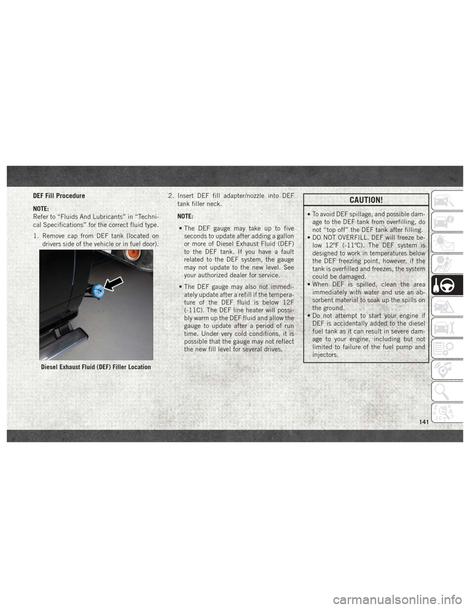
DEF Fill Procedure
NOTE:
Refer to “Fluids And Lubricants” in “Techni-
cal Specifications” for the correct fluid type.
1. Remove cap from DEF tank (located ondrivers side of the vehicle or in fuel door). 2. Insert DEF fill adapter/nozzle into DEF
tank filler neck.
NOTE: • The DEF gauge may take up to five seconds to update after adding a gallon
or more of Diesel Exhaust Fluid (DEF)
to the DEF tank. If you have a fault
related to the DEF system, the gauge
may not update to the new level. See
your authorized dealer for service.
• The DEF gauge may also not immedi- ately update after a refill if the tempera-
ture of the DEF fluid is below 12F
(-11C). The DEF line heater will possi-
bly warm up the DEF fluid and allow the
gauge to update after a period of run
time. Under very cold conditions, it is
possible that the gauge may not reflect
the new fill level for several drives.
CAUTION!
•To avoid DEF spillage, and possible dam-
age to the DEF tank from overfilling, do
not “top off” the DEF tank after filling.
• DO NOT OVERFILL. DEF will freeze be- low 12ºF (-11ºC). The DEF system is
designed to work in temperatures below
the DEF freezing point, however, if the
tank is overfilled and freezes, the system
could be damaged.
• When DEF is spilled, clean the area immediately with water and use an ab-
sorbent material to soak up the spills on
the ground.
• Do not attempt to start your engine if DEF is accidentally added to the diesel
fuel tank as it can result in severe dam-
age to your engine, including but not
limited to failure of the fuel pump and
injectors.
Diesel Exhaust Fluid (DEF) Filler Location
141
Page 144 of 298

CAUTION!
• Never add anything other than DEF tothe tank – especially any form of hydro-
carbon such as diesel fuel, fuel system
additives, gasoline, or any other
petroleum-based product. Even a very
small amount of these, less than
100 parts per million or less than 1 oz.
per 78 gallons (295 liters) will contami-
nate the entire DEF system and will
require replacement. If owners use a
container, funnel or nozzle when refilling
the tank, it should either be new or one
that is has only been used for adding
DEF. Mopar provides an attachable
nozzle with its DEF for this purpose.
3. Stop filling the DEF tank immediately when any of the following happen: DEF
stops flowing from the fill bottle into the
DEF tank, DEF splashes out the filler
neck, or a DEF pump nozzle automatically
shuts off.
4. Reinstall cap onto DEF tank. Filling The Def Tank In Cold Climates
Since DEF will begin to freeze at 12°F
(-11°C), your vehicle is equipped with an
automatic DEF heating system. This allows
the DEF injection system to operate properly
at temperatures below 12°F (-11°C). If your
vehicle is not in operation for an extended
period of time with temperatures below 12°F
(-11°C), the DEF in the tank may freeze. If
the tank is overfilled and freezes, it could be
damaged. Therefore, do not overfill the DEF
tank.
Extra care should be taken when filling with
portable containers to avoid overfilling. Note
the level of the DEF gauge in your instrument
cluster. You may safely add a maximum of
2 gallons (7.5 Liters) of DEF from portable
containers when your DEF gauge is reading ½
full.
TRAILER TOWING
Trailer Towing Weights (Maximum
Trailer Weight Ratings)
NOTE:
For trailer towing information (maximum
trailer weight ratings) refer to the following
website addresses:
•
ramtrucks.com/en/towing_guide/
• ramtruck.ca (Canada)
• rambodybuilder.com
Towing Requirements
To promote proper break-in of your new ve-
hicle drivetrain components, the following
guidelines are recommended.
CAUTION!
• Do not tow a trailer at all during the first
500 miles (805 km) the new vehicle is
driven. The engine, axle or other parts
could be damaged.
STARTING AND OPERATING
142
Page 158 of 298

CavityCartridge Fuse Micro Fuse Description
F09 40 Amp Green (Special
Services Vehicle & Cum- mins Diesel) –
Diesel Fuel Heater – If Equipped
F10 40 Amp Green –Body Controller / Exterior Lighting #2
F10 50 Amp Red –Body Controller / Exterior Lighting #2 – If Equipped with
Stop/Start
F11 30 Amp Pink –Integrated Trailer Brake Module – If Equipped
F12 40 Amp Green –Body Controller #3 / Power Locks
F13 40 Amp Green – Blower Motor
F14 40 Amp Green –Body Controller #4 / Interior Lighting
F16 30 Amp Pink –Smart Bar – If Equipped
F19 20 Amp Blue (1500 LD
Diesel)
30 Amp Pink (Cummins Diesel) –
SCR – If Equipped
F20 30 Amp Pink –Passenger Door Module
F21 30 Amp Pink –Drive Train Control Module
F22 20 Amp Blue
30 Amp Pink (Cummins Diesel) –
Engine Control Module
F23 30 Amp Pink –Body Controller #1 / Interior Lighting
F24 30 Amp Pink –Driver Door Module
F25 30 Amp Pink – Front Wiper
F26 30 Amp Pink –Antilock Brakes / Stability Control Module / Valves
F28 20 Amp Blue –Trailer Tow Backup Lights – If Equipped
IN CASE OF EMERGENCY
156
Page 159 of 298
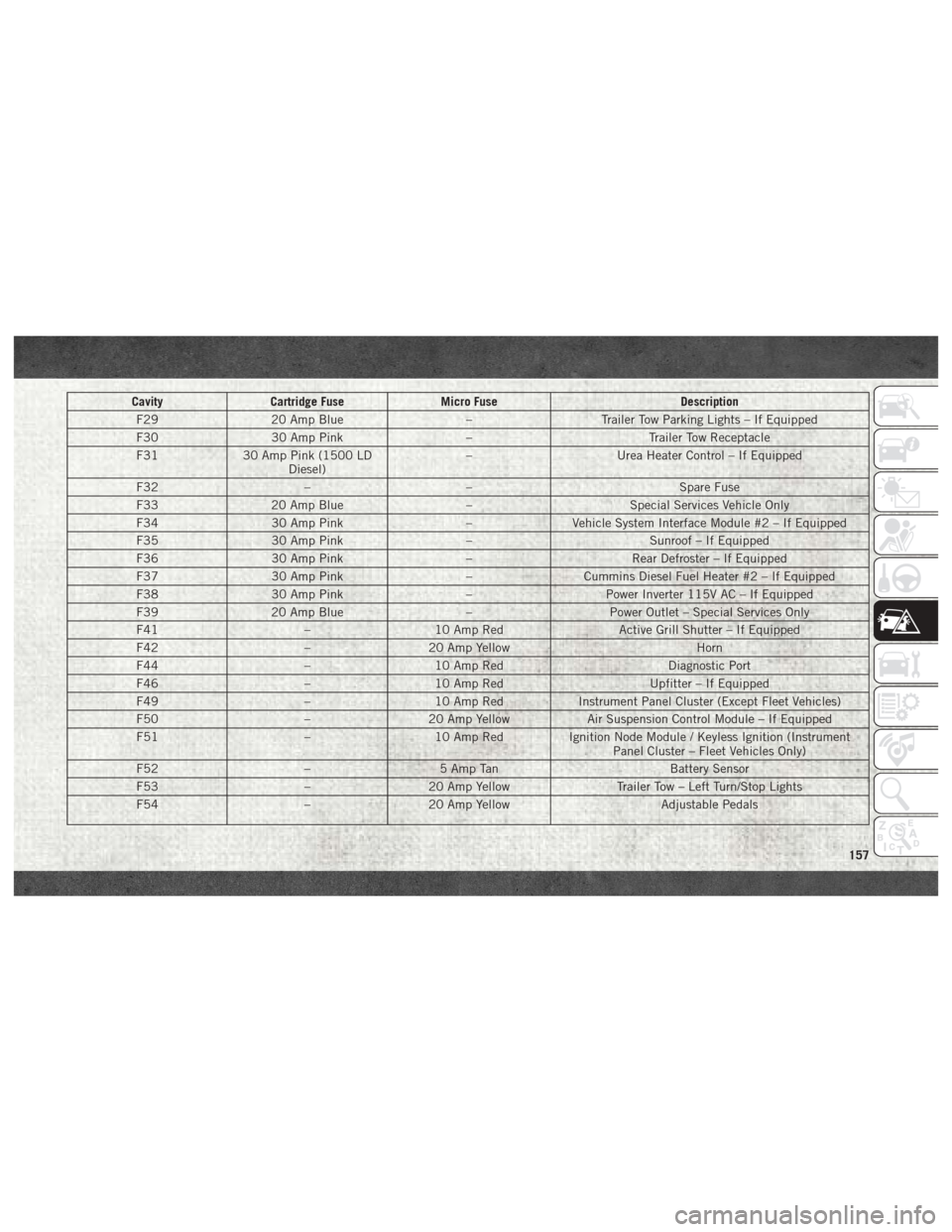
CavityCartridge Fuse Micro Fuse Description
F29 20 Amp Blue –Trailer Tow Parking Lights – If Equipped
F30 30 Amp Pink –Trailer Tow Receptacle
F31 30 Amp Pink (1500 LD
Diesel) –
Urea Heater Control – If Equipped
F32 –– Spare Fuse
F33 20 Amp Blue –Special Services Vehicle Only
F34 30 Amp Pink –Vehicle System Interface Module #2 – If Equipped
F35 30 Amp Pink –Sunroof – If Equipped
F36 30 Amp Pink –Rear Defroster – If Equipped
F37 30 Amp Pink –Cummins Diesel Fuel Heater #2 – If Equipped
F38 30 Amp Pink –Power Inverter 115V AC – If Equipped
F39 20 Amp Blue –Power Outlet – Special Services Only
F41 –10 Amp Red Active Grill Shutter – If Equipped
F42 –20 Amp Yellow Horn
F44 –10 Amp Red Diagnostic Port
F46 –10 Amp Red Upfitter – If Equipped
F49 –10 Amp Red Instrument Panel Cluster (Except Fleet Vehicles)
F50 –20 Amp Yellow Air Suspension Control Module – If Equipped
F51 –10 Amp Red Ignition Node Module / Keyless Ignition (Instrument
Panel Cluster – Fleet Vehicles Only)
F52 –5 Amp Tan Battery Sensor
F53 –20 Amp Yellow Trailer Tow – Left Turn/Stop Lights
F54 –20 Amp Yellow Adjustable Pedals
157
Page 160 of 298
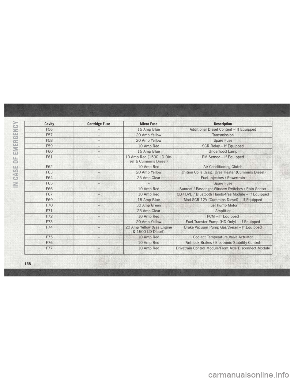
CavityCartridge Fuse Micro Fuse Description
F56 –15 Amp Blue Additional Diesel Content – If Equipped
F57 –20 Amp Yellow Transmission
F58 –20 Amp Yellow Spare Fuse
F59 –10 Amp Red SCR Relay – If Equipped
F60 –15 Amp Blue Underhood Lamp
F61 –10 Amp Red (1500 LD Die-
sel & Cummins Diesel) PM Sensor – If Equipped
F62 –10 Amp Red Air Conditioning Clutch
F63 –20 Amp Yellow Ignition Coils (Gas), Urea Heater (Cummins Diesel)
F64 –25 Amp Clear Fuel Injectors / Powertrain
F65 –– Spare Fuse
F66 –10 Amp Red Sunroof / Passenger Window Switches / Rain Sensor
F67 –10 Amp Red CD / DVD / Bluetooth Hands-free Module – If Equipped
F69 –15 Amp Blue Mod SCR 12V (Cummins Diesel) – If Equipped
F70 –30 Amp Green Fuel Pump Motor
F71 –25 Amp Clear Amplifier
F72 –10 Amp Red PCM – If Equipped
F73 –20 Amp Yellow Fuel Transfer Pump (HD Only) – If Equipped
F74 –20 Amp Yellow (Gas Engine
& 1500 LD Diesel) Brake Vacuum Pump Gas/Diesel – If Equipped
F75 –10 Amp Red Coolant Temperature Valve Actuator
F76 –10 Amp Red Antilock Brakes / Electronic Stability Control
F77 –10 Amp Red Drivetrain Control Module/Front Axle Disconnect Module
IN CASE OF EMERGENCY
158
Page 168 of 298

NOTE:
Do not jump off fuses. Only jump directly off
positive post.
2. Connect the opposite end of the positive (+) jumper cable to the positive (+)post of
the booster battery.
3. Connect the negative (-)end of the jumper
cable to the negative (-)post of the
booster battery.
4. Connect the opposite end of the negative (-)jumper cable to a good engine ground
(exposed metal part of the discharged
vehicle’s engine) away from the battery
and the fuel injection system.
WARNING!
Do not connect the jumper cable to the
negative (-) post of the discharged battery.
The resulting electrical spark could cause
the battery to explode and could result in
personal injury. Only use the specific
ground point, do not use any other exposed
metal parts. 5. Start the engine in the vehicle that has
the booster battery, let the engine idle a
few minutes, and then start the engine in
the vehicle with the discharged battery.
CAUTION!
Do not connect jumper cable to any of the
fuses on the positive battery terminal. The
resulting electrical current will blow the
fuse.
6. Once the engine is started, remove the jumper cables in the reverse sequence:
Disconnecting The Jumper Cables
1. Disconnect the negative (-)end of the
jumper cable from the engine ground of
the vehicle with the discharged battery.
2. Disconnect the opposite end of the nega- tive (-)jumper cable from the negative (-)
post of the booster battery.
3. Disconnect the positive (+)end of the
jumper cable from the positive (+)post of
the booster battery. 4. Disconnect the opposite end of the posi-
tive (+)jumper cable from the positive (+)
post of the vehicle with the discharged
battery.
If frequent jump starting is required to start
your vehicle you should have the battery and
charging system inspected at an authorized
dealer.
CAUTION!
Accessories plugged into the vehicle
power outlets draw power from the vehi-
cle’s battery, even when not in use (i.e.,
cellular devices, etc.). Eventually, if
plugged in long enough without engine
operation, the vehicle’s battery will dis-
charge sufficiently to degrade battery life
and/or prevent the engine from starting.
IF YOUR ENGINE OVERHEATS
In any of the following situations, you can
reduce the potential for overheating by taking
the appropriate action.
• On the highways — slow down.
IN CASE OF EMERGENCY
166
Page 175 of 298
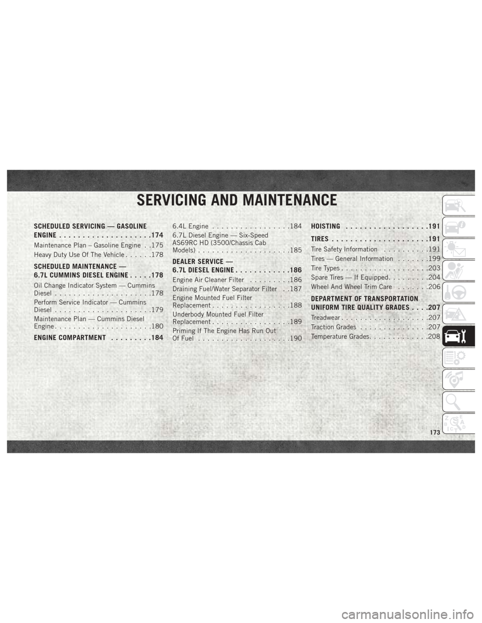
SERVICING AND MAINTENANCE
SCHEDULED SERVICING — GASOLINE
ENGINE................... .174
Maintenance Plan – Gasoline Engine . .175
Heavy Duty Use Of The Vehicle ......178
SCHEDULED MAINTENANCE —
6.7L CUMMINS DIESEL ENGINE.....178
Oil Change Indicator System — Cummins
Diesel.....................178
Perform Service Indicator — Cummins
Diesel .....................179
Maintenance Plan — Cummins Diesel
Engine .....................180
ENGINE COMPARTMENT .........184
6.4L Engine.................184
6.7L Diesel Engine — Six-Speed
AS69RC HD (3500/Chassis Cab
Models) ....................185
DEALER SERVICE —
6.7L DIESEL ENGINE ............186
Engine Air Cleaner Filter .........186
Draining Fuel/Water Separator Filter . .187
Engine Mounted Fuel Filter
Replacement .................188
Underbody Mounted Fuel Filter
Replacement .................189
Priming If The Engine Has Run Out
Of Fuel ....................190
HOISTING ................. .191
TIRES .................... .191
Tire Safety Information..........191
Tires — General Information .......199
Tire Types ...................203
Spare Tires — If Equipped .........204
Wheel And Wheel Trim Care .......206
DEPARTMENT OF TRANSPORTATION
UNIFORM TIRE QUALITY GRADES . . . .207
Treadwear...................207
Traction Grades ...............207
Temperature Grades .............208
SERVICING AND MAINTENANCE
173
Page 176 of 298
SCHEDULED SERVICING — GASOLINE
ENGINE
Your vehicle is equipped with an automatic
oil change indicator system. The oil change
indicator system will remind you that it is
time to take your vehicle in for scheduled
maintenance.
Based on engine operation conditions, the oil
change indicator message will illuminate.
This means that service is required for your
vehicle. Operating conditions such as fre-
quent short-trips, trailer tow, extremely hot or
cold ambient temperatures, and E85 fuel
usage will influence when the “Oil Change
Required” message is displayed. Severe Op-
erating Conditions can cause the change oil
message to illuminate as early as
3,500 miles (5,600 km) since last reset.
Have your vehicle serviced as soon as pos-
sible, within the next 500 miles (805 km).
Your authorized dealer will reset the oil
change indicator message after completing
the scheduled oil change. If a scheduled oil
change is performed by someone other than
your authorized dealer, the message can bereset by referring to the steps described under
“Warning And Indicator Lights” or “Instru-
ment Cluster Display” in “Getting To Know
Your Instrument Panel” in your Owner’s
Manual at
www.mopar.com/en-us/care/
owner-manual.html (U.S. Residents) or
www.owners.mopar.ca (Canadian Residents)
for further information.
Gasoline Engines:
Under no circumstances should oil change
intervals exceed 8,000 miles (13,000 km),
twelve months or 350 hours of engine run
time, whichever comes first. The 350 hours
of engine run or idle time is generally only a
concern for fleet customers.
Severe Duty:
Change Engine Oil at 4,000 miles
(6,500 km) or 350 hours of engine run time
if the vehicle is operated in a dusty and off
road environment or is operated predomi-
nately at idle or very low engine RPM’s. This
type of vehicle use is considered Severe Duty. Once A Month Or Before A Long Trip:
• Check engine oil level
• Check windshield washer fluid level
• Check the tire inflation pressures and look
for unusual wear or damage
• Check the fluid levels of the coolant reser- voir, brake master cylinder, power steering
and automatic transmission, and fill as
needed
• Check function of all interior and exterior lights
SERVICING AND MAINTENANCE
174