lights Ram 4500 Chassis Cab 2018 Owner's Manual
[x] Cancel search | Manufacturer: RAM, Model Year: 2018, Model line: 4500 Chassis Cab, Model: Ram 4500 Chassis Cab 2018Pages: 298, PDF Size: 5.88 MB
Page 120 of 298

Lights
Have someone observe the operation of brake
lights and exterior lights while you work the
controls. Check turn signal and high beam
indicator lights on the instrument panel.
Door Latches
Check for proper closing, latching, and lock-
ing.
Fluid Leaks
Check area under the vehicle after overnight
parking for fuel, coolant, oil, or other fluid
leaks. Also, if gasoline fumes are detected or
if fuel, or brake fluid leaks are suspected. The
cause should be located and corrected imme-
diately.
SAFETY
118
Page 127 of 298
NORMAL OPERATION — 6.7L DIESEL
ENGINE
Observe the following when the engine is
operating.
• All message center lights are off.
• Malfunction Indicator Light (MIL) is off.
• Engine oil pressure is above 10 psi(69 kPa) at idle.
• Voltmeter operation:
The voltmeter may show a gauge fluctuation
at various engine temperatures. This cycling
operation is caused by the post-heat cycle of
the intake manifold heater system. The num-
ber of cycles and the length of the cycling
operation is controlled by the engine control
module. Post-heat operation can run for sev-
eral minutes, and then the electrical system
and voltmeter needle will stabilize.
The cycling action will cause temporary dim-
ming of the headlamps, interior lamps, and
also a noticeable reduction in blower motor
speed.
Cold Weather Precautions
Operation in ambient temperature below
32°F (0°C) may require special consider-
ations. The following charts suggest these
options:
Winter Front Cover Usage
A winter front or cold weather cover is to be
used in ambient temperatures below 32°F
(0°C), especially during extended idle condi-
tions. This cover is equipped with four flaps
for managing total grille opening in varying
ambient temperatures. If a winter front or
cold weather cover is to be used the flaps
should be left in the full open position to
allow air flow to the charge air cooler and
automatic transmission oil cooler. When am-
bient temperatures drop below 0°F (-17°C)
the four flaps need to be closed. A suitable
cold weather cover is available from your
Mopar dealer.
Engine Idling
Avoid prolonged idling, long periods of idling
may be harmful to your engine because com-
bustion chamber temperatures can drop so low that the fuel may not burn completely.
Incomplete combustion allows carbon and
varnish to form on piston rings, engine valves,
and injector nozzles. Also, the unburned fuel
can enter the crankcase, diluting the oil and
causing rapid wear to the engine.
If the engine is allowed to idle or the truck is
driven on low engine speed drive cycles for
more than 2 hours, the system will automati-
cally enter an emissions operating mode that
will increase the engine idle speed to
900 RPM (1050 RPM for Chassis Cab).
While in this mode, which is designed to help
maintain the diesel particulate filter, the en-
gine idle speed will return to normal when the
brake pedal is applied. A small change in
engine tone or a slight change in engine
performance while accelerating may also be
noticeable at speeds below 20 mph
(32 kmh). This operating mode may last for
up to an hour of idle time, or around 20 min-
utes of driving time.
Your truck may have been ordered with an
optional voltage monitoring idle up feature. If
a load is placed on the electrical system while
the truck is in park, this feature will attempt
125
Page 152 of 298

NOTE:
With electronic shift transfer case:
• Steps 2 through 4 are requirements thatmust be met before pushing the NEUTRAL
(N) button, and must continue to be met
until the shift has been completed. If any of
these requirements are not met before
pushing the NEUTRAL (N) button or are no
longer met during the shift, the NEUTRAL
(N) indicator light will flash continuously
until all requirements are met or until the
NEUTRAL (N) button is released.
• The ignition must be in the ON/RUN mode for a shift to take place and for the position
indicator lights to be operable. If the igni-
tion is not in the ON/RUN mode, the shift
will not take place and no position indicator
lights will be on or flashing.
• A flashing NEUTRAL (N) position indicator light indicates that shift requirements have
not been met.Shifting Out Of NEUTRAL (N)
Use the following procedure to prepare your
vehicle for normal usage:
1. Bring the vehicle to a complete stop,
leaving it connected to the tow vehicle.
2. Firmly apply the parking brake.
3. Turn the ignition to the ON/RUN mode, but do not start the engine.
4. Press and hold the brake pedal.
5. Shift the transmission into NEUTRAL.
• With manual shift transfer case, shiftthe transfer case lever to the desired
position.
• With electronic shift transfer case with rotary selector switch, push and hold
the transfer case NEUTRAL (N) button
until the NEUTRAL (N) indicator light
turns off. After the NEUTRAL (N) indi-
cator light turns off, release the NEU-
TRAL (N) button. After the NEUTRAL
(N) button has been released, the
transfer case will shift to the position
indicated by the selector switch. • With electronic shift transfer case with
push-button selector switch, push and
hold the switch for the desired transfer
case position, until the NEUTRAL (N)
indicator light turns off and the desired
position indicator light turns on.
NOTE:
When shifting out of transfer case NEUTRAL
(N), the engine should remain OFF to avoid
gear clash.
6. Shift automatic transmission into PARK.
7. Release the brake pedal (and clutch pedal on a manual transmission).
8. Disconnect vehicle from the tow vehicle.
9. Start the engine.
10. Press and hold the brake pedal.
11. Release the parking brake.
12. Shift the transmission into gear, release the brake pedal (and clutch pedal on
manual transmissions), and check that
the vehicle operates normally.
STARTING AND OPERATING
150
Page 153 of 298

NOTE:
With electronic shift transfer case:
• Steps 3 and 4 are requirements that mustbe met before pushing the button to shift
out of NEUTRAL (N), and must continue to
be met until the shift has been completed.
If any of these requirements are not met
before pushing the button or are no longer
met during the shift, the NEUTRAL (N)
indicator light will flash continuously until
all requirements are met or until the button
is released. • The ignition must be in the ON/RUN mode
for a shift to take place and for the position
indicator lights to be operable. If the igni-
tion is not in the ON/RUN mode, the shift
will not take place and no position indicator
lights will be on or flashing.
• A flashing NEUTRAL (N) position indicator light indicates that shift requirements have
not been met.
151
Page 158 of 298

CavityCartridge Fuse Micro Fuse Description
F09 40 Amp Green (Special
Services Vehicle & Cum- mins Diesel) –
Diesel Fuel Heater – If Equipped
F10 40 Amp Green –Body Controller / Exterior Lighting #2
F10 50 Amp Red –Body Controller / Exterior Lighting #2 – If Equipped with
Stop/Start
F11 30 Amp Pink –Integrated Trailer Brake Module – If Equipped
F12 40 Amp Green –Body Controller #3 / Power Locks
F13 40 Amp Green – Blower Motor
F14 40 Amp Green –Body Controller #4 / Interior Lighting
F16 30 Amp Pink –Smart Bar – If Equipped
F19 20 Amp Blue (1500 LD
Diesel)
30 Amp Pink (Cummins Diesel) –
SCR – If Equipped
F20 30 Amp Pink –Passenger Door Module
F21 30 Amp Pink –Drive Train Control Module
F22 20 Amp Blue
30 Amp Pink (Cummins Diesel) –
Engine Control Module
F23 30 Amp Pink –Body Controller #1 / Interior Lighting
F24 30 Amp Pink –Driver Door Module
F25 30 Amp Pink – Front Wiper
F26 30 Amp Pink –Antilock Brakes / Stability Control Module / Valves
F28 20 Amp Blue –Trailer Tow Backup Lights – If Equipped
IN CASE OF EMERGENCY
156
Page 159 of 298
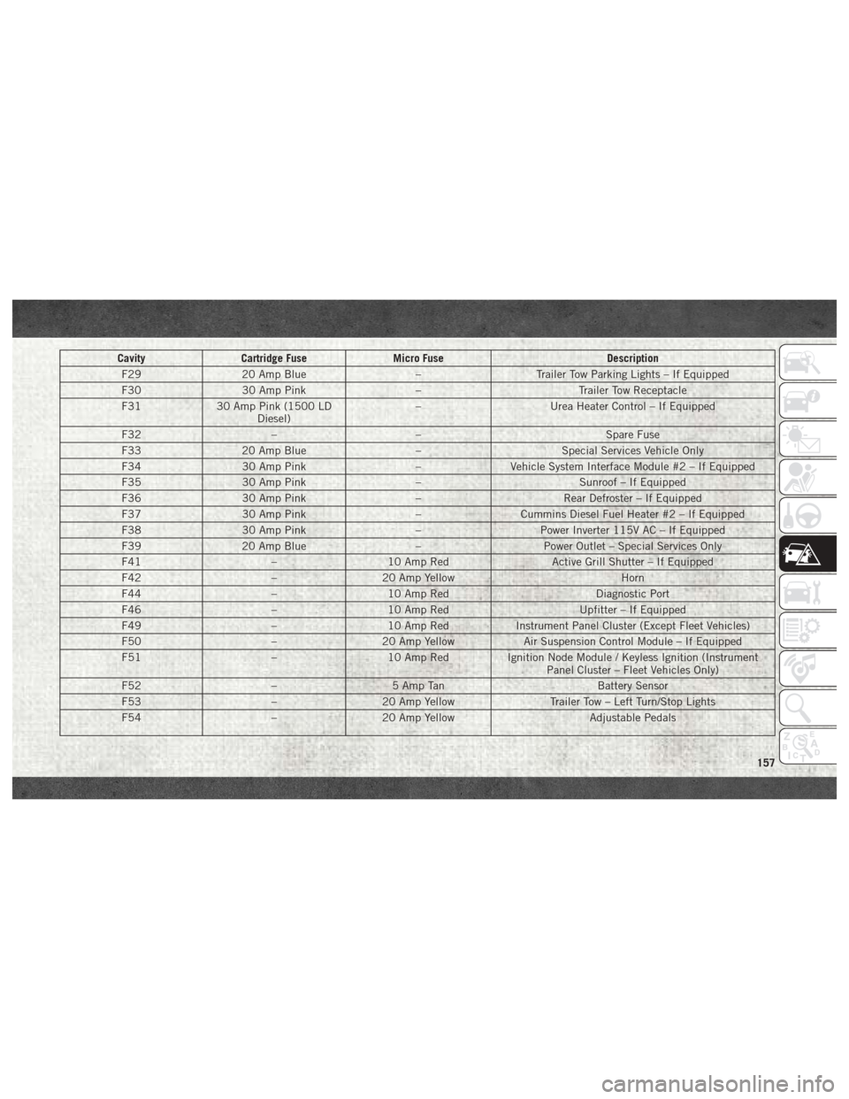
CavityCartridge Fuse Micro Fuse Description
F29 20 Amp Blue –Trailer Tow Parking Lights – If Equipped
F30 30 Amp Pink –Trailer Tow Receptacle
F31 30 Amp Pink (1500 LD
Diesel) –
Urea Heater Control – If Equipped
F32 –– Spare Fuse
F33 20 Amp Blue –Special Services Vehicle Only
F34 30 Amp Pink –Vehicle System Interface Module #2 – If Equipped
F35 30 Amp Pink –Sunroof – If Equipped
F36 30 Amp Pink –Rear Defroster – If Equipped
F37 30 Amp Pink –Cummins Diesel Fuel Heater #2 – If Equipped
F38 30 Amp Pink –Power Inverter 115V AC – If Equipped
F39 20 Amp Blue –Power Outlet – Special Services Only
F41 –10 Amp Red Active Grill Shutter – If Equipped
F42 –20 Amp Yellow Horn
F44 –10 Amp Red Diagnostic Port
F46 –10 Amp Red Upfitter – If Equipped
F49 –10 Amp Red Instrument Panel Cluster (Except Fleet Vehicles)
F50 –20 Amp Yellow Air Suspension Control Module – If Equipped
F51 –10 Amp Red Ignition Node Module / Keyless Ignition (Instrument
Panel Cluster – Fleet Vehicles Only)
F52 –5 Amp Tan Battery Sensor
F53 –20 Amp Yellow Trailer Tow – Left Turn/Stop Lights
F54 –20 Amp Yellow Adjustable Pedals
157
Page 161 of 298

CavityCartridge Fuse Micro Fuse Description
F78 –10 Amp Red Engine Control Module / Electric Power Steering
F79 –15 Amp Blue Clearance Lights
F80 –10 Amp Red Universal Garage Door Opener / Compass
F81 –20 Amp Yellow Trailer Tow Right Turn / Stop Lights
F82 –10 Amp Red Steering Column Control Module / Cruise Control
F84 –15 Amp Blue Switch Bank / Instrument Cluster
F85 –10 Amp Red Airbag Module
F86 –10 Amp Red Airbag Module
F87 –10 Amp Red Air Suspension – If Equipped / Trailer Tow / Steering Col-
umn Control Module
F88 –15 Amp Blue Instrument Panel Cluster
F90/F91 –20 Amp Yellow Power Outlet (Rear Seats) Customer Selectable
F93 –20 Amp Yellow Cigar Lighter
F94 –10 Amp Red Shifter / Transfer Case Module
F95 –10 Amp Red Rear Camera / Park Assist
F96 –10 Amp Red Rear Seat Heater Switch
F97 –25 Amp Clear Rear Heated Seats & Heated Steering Wheel – If
Equipped
F98 –25 Amp Clear Front Heated Seats – If Equipped
F99 –10 Amp Red Climate Control
F100 –10 Amp Red Upfitters – If Equipped
F101 –15 Amp Blue Electrochromatic Mirror / Smart High Beams – If
Equipped
F104 –20 Amp Yellow Power Outlets (Instrument Panel / Center Console)
159
Page 176 of 298
SCHEDULED SERVICING — GASOLINE
ENGINE
Your vehicle is equipped with an automatic
oil change indicator system. The oil change
indicator system will remind you that it is
time to take your vehicle in for scheduled
maintenance.
Based on engine operation conditions, the oil
change indicator message will illuminate.
This means that service is required for your
vehicle. Operating conditions such as fre-
quent short-trips, trailer tow, extremely hot or
cold ambient temperatures, and E85 fuel
usage will influence when the “Oil Change
Required” message is displayed. Severe Op-
erating Conditions can cause the change oil
message to illuminate as early as
3,500 miles (5,600 km) since last reset.
Have your vehicle serviced as soon as pos-
sible, within the next 500 miles (805 km).
Your authorized dealer will reset the oil
change indicator message after completing
the scheduled oil change. If a scheduled oil
change is performed by someone other than
your authorized dealer, the message can bereset by referring to the steps described under
“Warning And Indicator Lights” or “Instru-
ment Cluster Display” in “Getting To Know
Your Instrument Panel” in your Owner’s
Manual at
www.mopar.com/en-us/care/
owner-manual.html (U.S. Residents) or
www.owners.mopar.ca (Canadian Residents)
for further information.
Gasoline Engines:
Under no circumstances should oil change
intervals exceed 8,000 miles (13,000 km),
twelve months or 350 hours of engine run
time, whichever comes first. The 350 hours
of engine run or idle time is generally only a
concern for fleet customers.
Severe Duty:
Change Engine Oil at 4,000 miles
(6,500 km) or 350 hours of engine run time
if the vehicle is operated in a dusty and off
road environment or is operated predomi-
nately at idle or very low engine RPM’s. This
type of vehicle use is considered Severe Duty. Once A Month Or Before A Long Trip:
• Check engine oil level
• Check windshield washer fluid level
• Check the tire inflation pressures and look
for unusual wear or damage
• Check the fluid levels of the coolant reser- voir, brake master cylinder, power steering
and automatic transmission, and fill as
needed
• Check function of all interior and exterior lights
SERVICING AND MAINTENANCE
174
Page 221 of 298
MOPAR ACCESSORIES
Authentic Accessories By Mopar
• In choosing Authentic Accessories you gainfar more than expressive style, premium
protection, or extreme entertainment, you
also benefit from enhancing your vehicle
with accessories that have been thoroughly
tested and factory-approved. • The following highlights just some of the
many Authentic Ram Accessories by Mopar
featuring a fit, finish, and functionality spe-
cifically for your Ram.
• For the full line of Authentic Ram Accesso- ries by Mopar, visit your local dealership or
online at mopar.com for U.S. residents and
mopar.ca for Canadian residents. NOTE:
All parts are subject to availability.
EXTERIOR:
• Tubular Side Steps
• Stirrup Step• Front Air Deflectors
• Running Boards • Bodyside Moldings• Side Window Deflectors
INTERIOR:
• Premium Carpet Mats • Door Sill Guards• Leather Seats
• DOT Certified Emergency Kit • Slush Mats
ELECTRONICS:
• Trailer Brake Module • Wireless Charging Pad• Remote Start
• Electronic Vehicle Tracking
219
Page 252 of 298
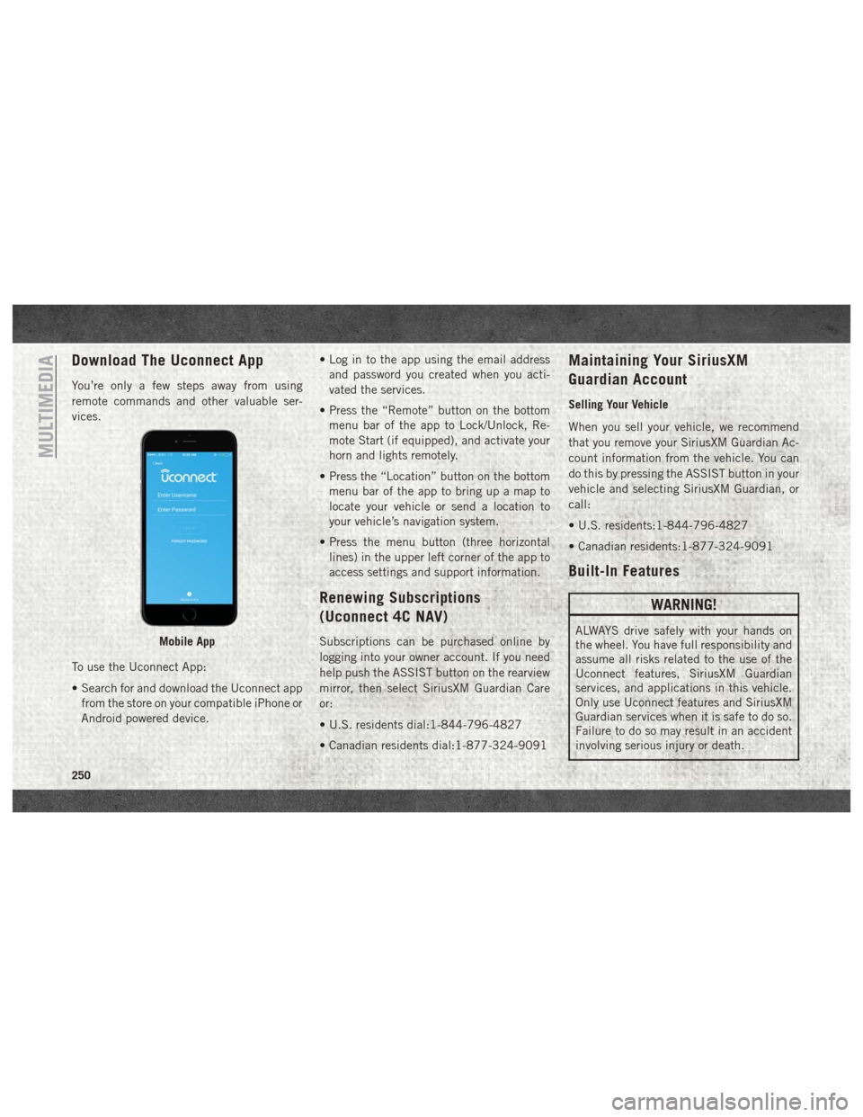
Download The Uconnect App
You’re only a few steps away from using
remote commands and other valuable ser-
vices.
To use the Uconnect App:
• Search for and download the Uconnect appfrom the store on your compatible iPhone or
Android powered device. • Log in to the app using the email address
and password you created when you acti-
vated the services.
• Press the “Remote” button on the bottom menu bar of the app to Lock/Unlock, Re-
mote Start (if equipped), and activate your
horn and lights remotely.
• Press the “Location” button on the bottom menu bar of the app to bring up a map to
locate your vehicle or send a location to
your vehicle’s navigation system.
• Press the menu button (three horizontal lines) in the upper left corner of the app to
access settings and support information.
Renewing Subscriptions
(Uconnect 4C NAV)
Subscriptions can be purchased online by
logging into your owner account. If you need
help push the ASSIST button on the rearview
mirror, then select SiriusXM Guardian Care
or:
• U.S. residents dial:1-844-796-4827
• Canadian residents dial:1-877-324-9091
Maintaining Your SiriusXM
Guardian Account
Selling Your Vehicle
When you sell your vehicle, we recommend
that you remove your SiriusXM Guardian Ac-
count information from the vehicle. You can
do this by pressing the ASSIST button in your
vehicle and selecting SiriusXM Guardian, or
call:
• U.S. residents:1-844-796-4827
• Canadian residents:1-877-324-9091
Built-In Features
WARNING!
ALWAYS drive safely with your hands on
the wheel. You have full responsibility and
assume all risks related to the use of the
Uconnect features, SiriusXM Guardian
services, and applications in this vehicle.
Only use Uconnect features and SiriusXM
Guardian services when it is safe to do so.
Failure to do so may result in an accident
involving serious injury or death.Mobile App
MULTIMEDIA
250