maintenance Ram 4500 Chassis Cab 2018 Owner's Manual
[x] Cancel search | Manufacturer: RAM, Model Year: 2018, Model line: 4500 Chassis Cab, Model: Ram 4500 Chassis Cab 2018Pages: 298, PDF Size: 5.88 MB
Page 184 of 298
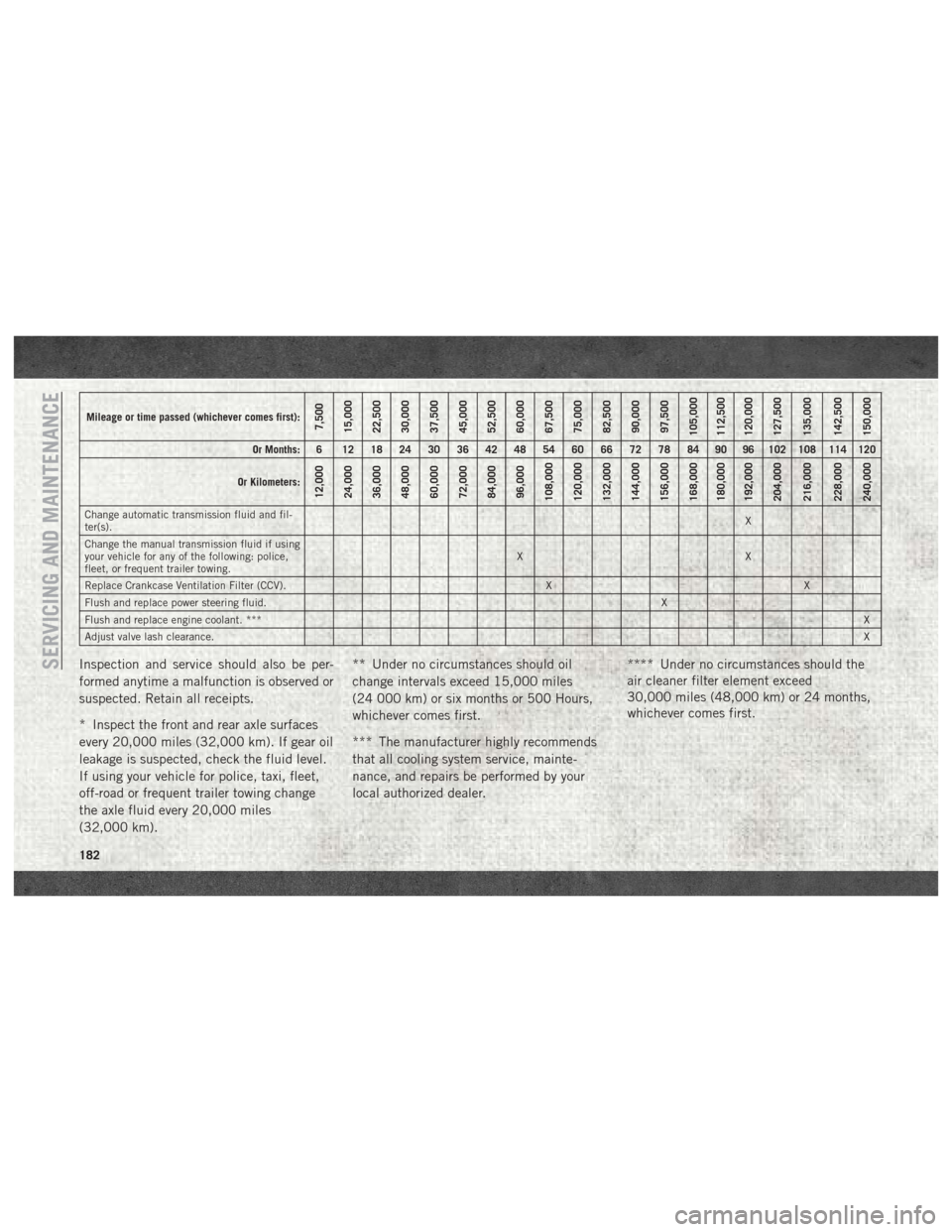
Mileage or time passed (whichever comes first):7,500
15,000
22,500
30,000
37,500
45,000
52,500
60,000
67,500
75,000
82,500
90,000
97,500
105,000
112,500
120,000
127,500
135,000
142,500
150,000
Or Months: 6 12 18 24 30 36 42 48 54 60 66 72 78 84 90 96 102 108 114 120
Or Kilometers:
12,000
24,000
36,000
48,000
60,000
72,000
84,000
96,000
108,000
120,000
132,000
144,000
156,000
168,000
180,000
192,000
204,000
216,000
228,000
240,000
Change automatic transmission fluid and fil-
ter(s). X
Change the manual transmission fluid if using
your vehicle for any of the following: police,
fleet, or frequent trailer towing. XX
Replace Crankcase Ventilation Filter (CCV). X X
Flush and replace power steering fluid. X
Flush and replace engine coolant. *** X
Adjust valve lash clearance. X
Inspection and service should also be per-
formed anytime a malfunction is observed or
suspected. Retain all receipts.
* Inspect the front and rear axle surfaces
every 20,000 miles (32,000 km). If gear oil
leakage is suspected, check the fluid level.
If using your vehicle for police, taxi, fleet,
off-road or frequent trailer towing change
the axle fluid every 20,000 miles
(32,000 km).** Under no circumstances should oil
change intervals exceed 15,000 miles
(24 000 km) or six months or 500 Hours,
whichever comes first.
*** The manufacturer highly recommends
that all cooling system service, mainte-
nance, and repairs be performed by your
local authorized dealer.
**** Under no circumstances should the
air cleaner filter element exceed
30,000 miles (48,000 km) or 24 months,
whichever comes first.SERVICING AND MAINTENANCE
182
Page 186 of 298
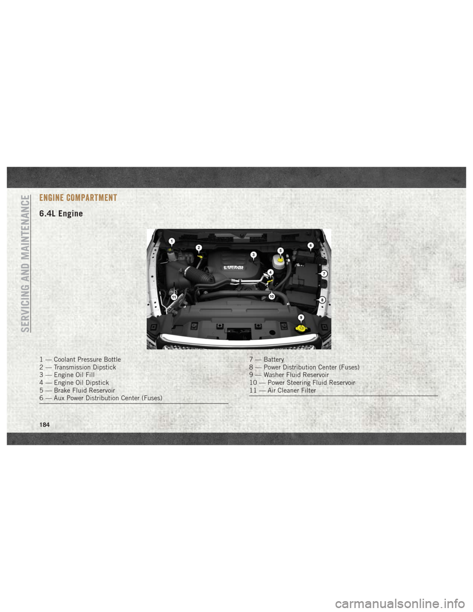
ENGINE COMPARTMENT
6.4L Engine
1 — Coolant Pressure Bottle
2 — Transmission Dipstick
3 — Engine Oil Fill
4 — Engine Oil Dipstick
5 — Brake Fluid Reservoir
6 — Aux Power Distribution Center (Fuses)7 — Battery
8 — Power Distribution Center (Fuses)
9 — Washer Fluid Reservoir
10 — Power Steering Fluid Reservoir
11 — Air Cleaner Filter
SERVICING AND MAINTENANCE
184
Page 188 of 298
DEALER SERVICE — 6.7L DIESEL
ENGINE
Your authorized dealer has the qualified ser-
vice personnel, special tools, and equipment
to perform all service operations in an expert
manner. Service Manuals are available which
include detailed service information for your
vehicle. Refer to these Service Manuals be-
fore attempting any procedure yourself.
NOTE:
Intentional tampering with emissions control
systems may void your warranty and could
result in civil penalties being assessed
against you.
WARNING!
You can be badly injured working on or
around a motor vehicle. Only do service
work for which you have the knowledge
and the proper equipment. If you have any
doubt about your ability to perform a ser-
vice job, take your vehicle to a competent
mechanic.
Engine Air Cleaner Filter
CAUTION!
All air entering the engine intake must be
filtered. The abrasive particles in unfil-
tered air will cause rapid wear to engine
components.
WARNING!
The air induction system (air cleaner,
hoses, etc.) provides a measure of protec-
tion. Do not remove the air induction sys-
tem (air cleaner, hoses, etc.) unless such
removal is necessary for repair or mainte-
nance. Make sure that no one is near the
engine compartment before starting the
vehicle with the air induction system (air
cleaner, hoses, etc.) removed. Failure to
do so can result in serious personal injury.
The condition of the air cleaner filter is moni-
tored by the Engine Control Module. The
“SERVICE AIR FILTER” message will display
in the instrument cluster when service is required. Refer to “Instrument Cluster Dis-
play” in “Getting To Know Your Instrument
Panel” for further information.
The “SERVICE AIR FILTER” message could
be displayed periodically. This is because
engine air flow requirements change based
on driving conditions. As the filter becomes
more restrictive and air flow requirements
increase the “SERVICE AIR FILTER” mes-
sage will be displayed. The message may not
be displayed in subsequent drive cycles if the
same conditions are not met. The air filter
element should be replaced within 250 miles
(402 km) from the first time this message is
displayed to ensure proper engine operation
during all driving conditions.
CAUTION!
Driving with a restricted air filter can
cause engine damage. Driving in dusty
environments for extended periods will
lead to rapid air filter plugging. Action
should be taken as soon as the “SERVICE
AIR FILTER” message is displayed.
SERVICING AND MAINTENANCE
186
Page 190 of 298
position, there may be a problem with your
water separator wiring or sensor. See your
authorized dealer for service.
Upon proper draining of the water from both
fuel filters, the “Water In Fuel Indicator
Light” will remain illuminated for approxi-
mately 10 seconds. If the water was drained
while the engine was running, the “Water In
Fuel Indicator Light” may remain on for ap-
proximately three minutes.
NOTE:
Care should be taken in disposing of used
fluids from your vehicle. Used fluids, indis-
criminately discarded, can present a problem
to the environment. Contact an authorized
dealer, service station, or government agency
for advice on recycling programs and for
where used fluids and filters can be properly
disposed of in your area.
Drain the fuel/water separator filters when
the “Water In Fuel Indicator Light” is ON.
Within 10 minutes of vehicle shutdown, turn
the engine mounted filter drain valve (located
on the side of the filter assembly) counter-
clockwise 1/4 turn, and turn the under body
mounted filter drain valve (located on thebottom of the filter assembly) counterclock
wise 1 full turn. Then turn the ignition switch
to the ON position, and allow any accumu-
lated water to drain. Leave the drain valve
open until all water and contaminants have
been removed. When clean fuel is visible,
close the drain valves by turning them fully
clockwise, and turn the ignition switch to
OFF.
If more than a couple ounces/milliliters of
fuel have been drained, follow the directions
for “Priming If The Engine Has Run Out Of
Fuel.”
Engine Mounted Fuel Filter
Replacement
NOTE:
• Using a fuel filter that does not meet the
manufacturer's filtration and water separat-
ing requirements can severely impact fuel
system life and reliability.
• The engine mounted filter housing is equipped with a No-Filter-No-Run (NFNR)
feature. Engine will not run if:
1. No filter is installed. 2. Inferior/Non-approved filter is used.
Use of OEM filter is required to ensure
vehicle will run.
CAUTION!
• Diesel fuel will damage blacktop pavingsurfaces. Drain the filter into an appro-
priate container.
• Do not prefill the fuel filter when install-
ing a new fuel filter. There is a possibility
debris could be introduced into the fuel
filter during this action. It is best to
install the filter dry and allow the in-tank
lift pump to prime the fuel system.
1. Ensure engine is turned off.
2. Place drain pan under the fuel filter drain hose.
3. Open the water drain valve 1/4 turn coun- terclockwise and completely drain fuel
and water into the approved container.
4. Close the water drain valve.
5. Remove lid using a socket or strap wrench. Rotate counterclockwise for re-
moval. Remove used o-ring and discard it.
SERVICING AND MAINTENANCE
188
Page 192 of 298

Priming If The Engine Has Run
Out Of Fuel
WARNING!
Do not open the high pressure fuel system
with the engine running. Engine operation
causes high fuel pressure. High pressure
fuel spray can cause serious injury or
death.
1. Add a substantial amount of fuel to the tank, approximately 2 to 5 gal (8L to
19L).
2. Turn ignition switch to the start position to engage starter for one second, return ig-
nition switch to run position. This will
activate in tank fuel pump for approxi-
mately 15 seconds. Repeat this process
twice.
3. Start the engine using the “Normal Start- ing” procedure. Refer to “Starting Proce-
dures” in “Starting and Operating” for
further information.
CAUTION!
Do not engage the starter motor for more
than 15 seconds at a time. Allow two
minutes between the cranking intervals.
NOTE:
The engine may run rough until the air is
forced from all the fuel lines.
WARNING!
Do not use alcohol or gasoline as a fuel
blending agent. They can be unstable un-
der certain conditions and be hazardous or
explosive when mixed with diesel fuel.
CAUTION!
Due to lack of lubricants in alcohol or
gasoline, the use of these fuels can cause
damage to the fuel system. NOTE:
• A maximum blend of 5% biodiesel, meet-
ing ASTM specification D-975 may be used
with your Cummins diesel engine. (Chassis
Cab models not configured with B20 capa-
bility.)
• A maximum blend of 20% biodiesel, meet- ing ASTM specification D-7467 may be
used with your Cummins diesel engine.
(Pickup models and Chassis Cab models
configured with B20 capability.)
• Use of biodiesel mixture in excess of 20% can negatively impact the fuel filter's abil-
ity to separate water from the fuel, resulting
in high pressure fuel system corrosion or
damage.
• Ethanol blends are not recommended or approved for use with your Cummins diesel
engine.
• In addition, commercially available fuel ad- ditives are not necessary for the proper
operation of your Cummins diesel engine.
SERVICING AND MAINTENANCE
190
Page 194 of 298
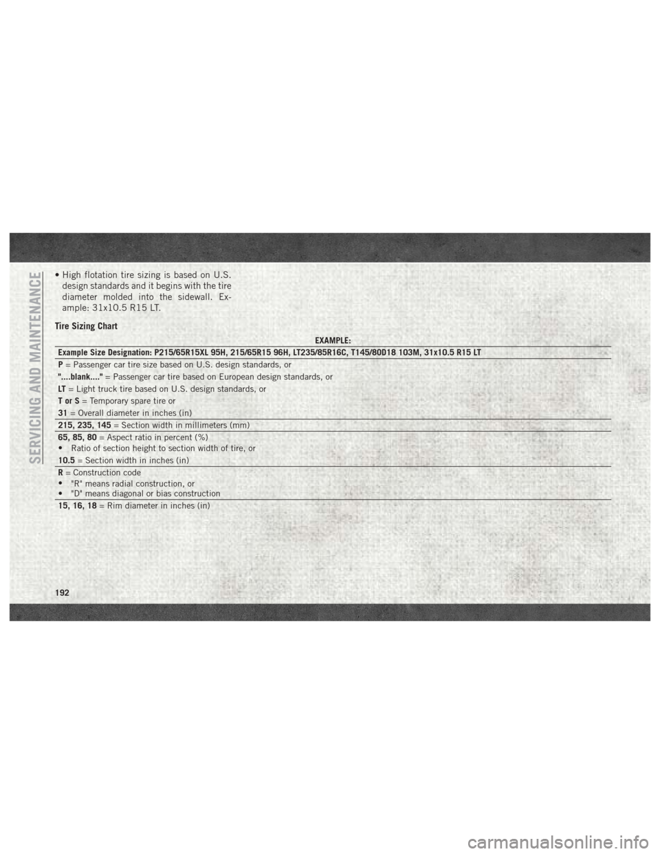
• High flotation tire sizing is based on U.S.design standards and it begins with the tire
diameter molded into the sidewall. Ex-
ample: 31x10.5 R15 LT.
Tire Sizing Chart
EXAMPLE:
Example Size Designation: P215/65R15XL 95H, 215/65R15 96H, LT235/85R16C, T145/80D18 103M, 31x10.5 R15 LT
P = Passenger car tire size based on U.S. design standards, or
"....blank...." = Passenger car tire based on European design standards, or
LT = Light truck tire based on U.S. design standards, or
TorS= Temporary spare tire or
31 = Overall diameter in inches (in)
215, 235, 145 = Section width in millimeters (mm)
65, 85, 80 = Aspect ratio in percent (%)
• Ratio of section height to section width of tire, or
10.5 = Section width in inches (in)
R = Construction code
• "R" means radial construction, or
• "D" means diagonal or bias construction
15, 16, 18 = Rim diameter in inches (in)
SERVICING AND MAINTENANCE
192
Page 196 of 298

Tire Identification Number (TIN)
The TIN may be found on one or both sides of
the tire; however, the date code may only be
on one side. Tires with white sidewalls will
have the full TIN, including the date code,located on the white sidewall side of the tire.
Look for the TIN on the outboard side of black
sidewall tires as mounted on the vehicle. If
the TIN is not found on the outboard side,
then you will find it on the inboard side of the
tire.
EXAMPLE:
DOT MA L9 ABCD 0301
DOT = Department of Transportation
• This symbol certifies that the tire is in compliance with the U.S. Department of Transportation tire safety standards and is approved for highway
use
MA = Code representing the tire manufacturing location (two digits)
L9 = Code representing the tire size (two digits)
ABCD = Code used by the tire manufacturer (one to four digits)
03 = Number representing the week in which the tire was manufactured (two digits)
• 03 means the 3rd week
01 = Number representing the year in which the tire was manufactured (two digits)
• 01 means the year 2001
• Prior to July 2000, tire manufacturers were only required to have one number to represent the year in which the tire was manufactured. Example:
031 could represent the 3rd week of 1981 or 1991
SERVICING AND MAINTENANCE
194
Page 198 of 298

Tire Loading And Tire Pressure
NOTE:
The proper cold tire inflation pressure is
listed on the driver’s side B-Pillar or the rear
edge of the driver's side door.
Check the inflation pressure of each tire,
including the spare tire (if equipped), at least
monthly and inflate to the recommended
pressure for your vehicle.Tire And Loading Information Placard This placard tells you important information
about the:
1. Number of people that can be carried in
the vehicle.
2. Total weight your vehicle can carry.
3. Tire size designed for your vehicle.
4. Cold tire inflation pressures for the front, rear, and spare tires.
Loading
The vehicle maximum load on the tire must
not exceed the load carrying capacity of the
tire on your vehicle. You will not exceed the
tire's load carrying capacity if you adhere to
the loading conditions, tire size, and cold tire
inflation pressures specified on the Tire and
Loading Information placard in “Vehicle
Loading” in the “Starting And Operating”
section of this manual.
NOTE:
Under a maximum loaded vehicle condition,
gross axle weight ratings (GAWRs) for the
front and rear axles must not be exceeded.
Example Tire Placard Location (Door)
Example Tire Placard Location (B-Pillar)
Tire And Loading Information Placard
SERVICING AND MAINTENANCE
196
Page 200 of 298

SERVICING AND MAINTENANCE
198
Page 202 of 298

Tire Inflation Pressures
The proper cold tire inflation pressure is
listed on the driver's side B-Pillar or rear edge
of the driver's side door.
At least once a month:
• Check and adjust tire pressure with a goodquality pocket-type pressure gauge. Do not
make a visual judgement when determining
proper inflation. Tires may look properly
inflated even when they are under-inflated.
• Inspect tires for signs of tire wear or visible damage.
CAUTION!
After inspecting or adjusting the tire pres-
sure, always reinstall the valve stem cap.
This will prevent moisture and dirt from
entering the valve stem, which could dam-
age the valve stem.
Inflation pressures specified on the placard
are always “cold tire inflation pressure”. Cold
tire inflation pressure is defined as the tire
pressure after the vehicle has not been driven
for at least three hours, or driven less than 1 mile (1.6 km) after sitting for a minimum of
three hours. The cold tire inflation pressure
must not exceed the maximum inflation pres-
sure molded into the tire sidewall.
Check tire pressures more often if subject to
a wide range of outdoor temperatures, as tire
pressures vary with temperature changes.
Tire pressures change by approximately 1 psi
(7 kPa) per 12°F (7°C) of air temperature
change. Keep this in mind when checking
tire pressure inside a garage, especially in the
Winter.
Example: If garage temperature = 68°F
(20°C) and the outside temperature = 32°F
(0°C) then the cold tire inflation pressure
should be increased by 3 psi (21 kPa), which
equals 1 psi (7 kPa) for every 12°F (7°C) for
this outside temperature condition.
Tire pressure may increase from 2 to 6 psi
(13 to 40 kPa) during operation. DO NOT
reduce this normal pressure build up or your
tire pressure will be too low.
Tire Pressures For High Speed Operation
The manufacturer advocates driving at safe
speeds and within posted speed limits.
Where speed limits or conditions are such
that the vehicle can be driven at high speeds,
maintaining correct tire inflation pressure is
very important. Increased tire pressure and
reduced vehicle loading may be required for
high-speed vehicle operation. Refer to your
authorized tire dealer or original equipment
vehicle dealer for recommended safe operat-
ing speeds, loading and cold tire inflation
pressures.
WARNING!
High speed driving with your vehicle under
maximum load is dangerous. The added
strain on your tires could cause them to
fail. You could have a serious collision. Do
not drive a vehicle loaded to the maximum
capacity at continuous speeds above
75 mph (120 km/h).SERVICING AND MAINTENANCE
200