oil Ram 4500 Chassis Cab 2018 Owner's Manual
[x] Cancel search | Manufacturer: RAM, Model Year: 2018, Model line: 4500 Chassis Cab, Model: Ram 4500 Chassis Cab 2018Pages: 298, PDF Size: 5.88 MB
Page 183 of 298

Mileage or time passed (whichever comes first):7,500
15,000
22,500
30,000
37,500
45,000
52,500
60,000
67,500
75,000
82,500
90,000
97,500
105,000
112,500
120,000
127,500
135,000
142,500
150,000
Or Months: 6 12 18 24 30 36 42 48 54 60 66 72 78 84 90 96 102 108 114 120
Or Kilometers:
12,000
24,000
36,000
48,000
60,000
72,000
84,000
96,000
108,000
120,000
132,000
144,000
156,000
168,000
180,000
192,000
204,000
216,000
228,000
240,000
Inspect wheel bearings. XX XX X
Additional Maintenance
Replace cabin air filter. XXX XX X
Replace engine fuel filter element. X X X X X X X X X X
Replace chassis mounted fuel filter element. X X X X X X X X X X
Inspect the front and rear axle surfaces. If
gear oil leakage is suspected, check the fluid
level. If using your vehicle for police, taxi,
fleet, off-road or frequent trailer towing
change the axle fluid. *
Inspect the transfer case fluid (4x4), change
for any of the following: police, taxi, fleet, or
frequent trailer towing. XX XX X
Change the transfer case fluid (4x4). XX
Change automatic transmission fluid
(AS69RC transmission only). XX XX X
Change the automatic transmission fluid and
sump filter (AS69RC transmission only). XX
Change automatic transmission fluid and fil-
ter(s) if using your vehicle for any of the fol-
lowing: police, fleet, or frequent trailer towing
(68RFE transmission only). XX
181
Page 184 of 298
Mileage or time passed (whichever comes first):7,500
15,000
22,500
30,000
37,500
45,000
52,500
60,000
67,500
75,000
82,500
90,000
97,500
105,000
112,500
120,000
127,500
135,000
142,500
150,000
Or Months: 6 12 18 24 30 36 42 48 54 60 66 72 78 84 90 96 102 108 114 120
Or Kilometers:
12,000
24,000
36,000
48,000
60,000
72,000
84,000
96,000
108,000
120,000
132,000
144,000
156,000
168,000
180,000
192,000
204,000
216,000
228,000
240,000
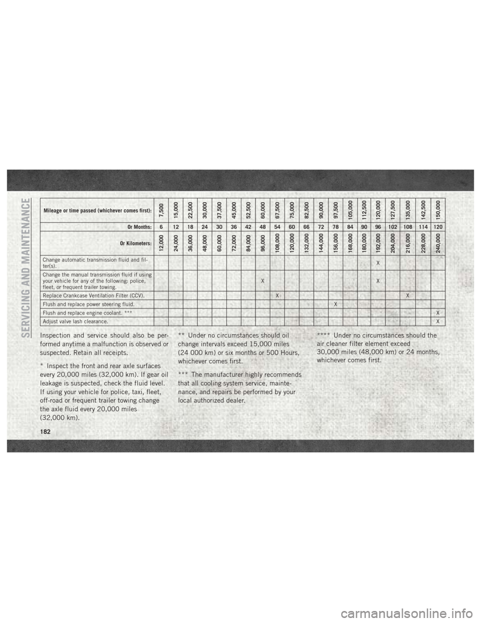
Change automatic transmission fluid and fil-
ter(s). X
Change the manual transmission fluid if using
your vehicle for any of the following: police,
fleet, or frequent trailer towing. XX
Replace Crankcase Ventilation Filter (CCV). X X
Flush and replace power steering fluid. X
Flush and replace engine coolant. *** X
Adjust valve lash clearance. X
Inspection and service should also be per-
formed anytime a malfunction is observed or
suspected. Retain all receipts.
* Inspect the front and rear axle surfaces
every 20,000 miles (32,000 km). If gear oil
leakage is suspected, check the fluid level.
If using your vehicle for police, taxi, fleet,
off-road or frequent trailer towing change
the axle fluid every 20,000 miles
(32,000 km).** Under no circumstances should oil
change intervals exceed 15,000 miles
(24 000 km) or six months or 500 Hours,
whichever comes first.
*** The manufacturer highly recommends
that all cooling system service, mainte-
nance, and repairs be performed by your
local authorized dealer.
**** Under no circumstances should the
air cleaner filter element exceed
30,000 miles (48,000 km) or 24 months,
whichever comes first.SERVICING AND MAINTENANCE
182
Page 186 of 298
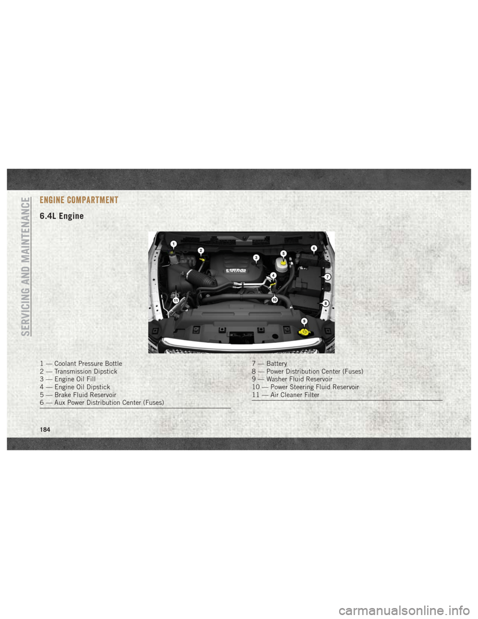
ENGINE COMPARTMENT
6.4L Engine
1 — Coolant Pressure Bottle
2 — Transmission Dipstick
3 — Engine Oil Fill
4 — Engine Oil Dipstick
5 — Brake Fluid Reservoir
6 — Aux Power Distribution Center (Fuses)7 — Battery
8 — Power Distribution Center (Fuses)
9 — Washer Fluid Reservoir
10 — Power Steering Fluid Reservoir
11 — Air Cleaner Filter
SERVICING AND MAINTENANCE
184
Page 187 of 298
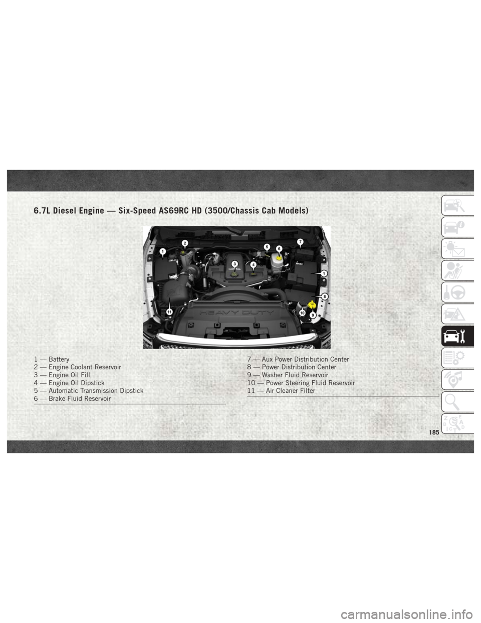
6.7L Diesel Engine — Six-Speed AS69RC HD (3500/Chassis Cab Models)
1 — Battery
2 — Engine Coolant Reservoir
3 — Engine Oil Fill
4 — Engine Oil Dipstick
5 — Automatic Transmission Dipstick
6 — Brake Fluid Reservoir7 — Aux Power Distribution Center
8 — Power Distribution Center
9 — Washer Fluid Reservoir
10 — Power Steering Fluid Reservoir
11 — Air Cleaner Filter
185
Page 191 of 298
6. Remove the used filter cartridge from thehousing and dispose of according to your
local regulations.
7. Wipe clean the sealing surfaces of the lid and housing.
8. Install new o-ring back into ring groove on the filter housing and lubricate with clean
engine oil.
9. Remove new filter cartridge from plastic bag and install into housing.
NOTE:
Do not remove cartridge from bag until
you reach this step in order to keep car-
tridge clean.
10. Push down on the cartridge to ensure it is properly seated. Do not pre-fill the filter
housing with fuel.
11. Install lid onto housing and tighten to 22.5 ft lbs (30.5 N.m). Do not over-
tighten the lid.
12. Prime the engine using the procedure in “Priming If The Engine Has Run Out Of
Fuel.” Then start the engine and confirm
there are no leaks.Underbody Mounted Fuel Filter
Replacement
NOTE:
• Using a fuel filter that does not meet themanufacturer's filtration and water separat-
ing requirements can severely impact fuel
system life and reliability.
• The underbody mounted filter housing will cause the engine not to run if:
1. No filter is installed.
CAUTION!
• Diesel fuel will damage blacktop paving surfaces. Drain the filter into an appro-
priate container.
• Do not prefill the fuel filter when install-
ing a new fuel filter. There is a possibility
debris could be introduced into the fuel
filter during this action. It is best to
install the filter dry and allow the in-tank
lift pump to prime the fuel system.
1. Ensure engine is turned off. 2. Place drain pan under the fuel filter drain
hose.
3. Open the water drain valve 1 full turn counterclockwise and completely drain
fuel and water into the approved
container.
4. Close the water drain valve.
5. Remove lid using a socket or strap wrench. Rotate counterclockwise for re-
moval. Remove used o-ring and discard it.
6. Remove the used filter cartridge from the housing and dispose of according to your
local regulations.
7. Wipe clean the sealing surfaces of the lid and housing.
8. Install new o-ring back into ring groove on the filter housing and lubricate with clean
engine oil.
NOTE:
WIF sensor is re-usable. Service kit comes
with new o-ring for filter canister and WIF
sensor.
189
Page 204 of 298
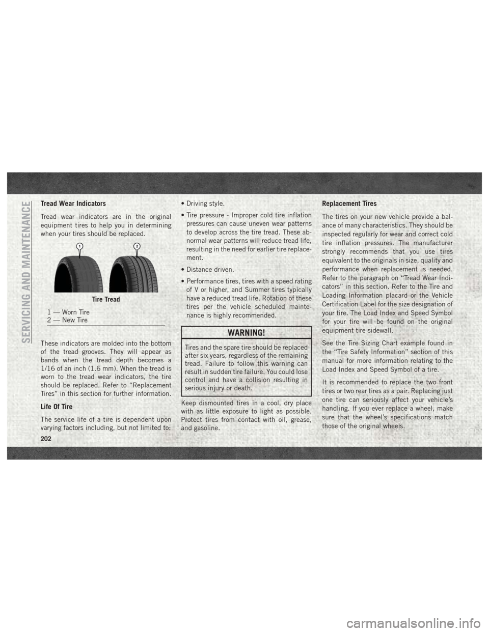
Tread Wear Indicators
Tread wear indicators are in the original
equipment tires to help you in determining
when your tires should be replaced.
These indicators are molded into the bottom
of the tread grooves. They will appear as
bands when the tread depth becomes a
1/16 of an inch (1.6 mm). When the tread is
worn to the tread wear indicators, the tire
should be replaced. Refer to “Replacement
Tires” in this section for further information.
Life Of Tire
The service life of a tire is dependent upon
varying factors including, but not limited to:• Driving style.
• Tire pressure - Improper cold tire inflation
pressures can cause uneven wear patterns
to develop across the tire tread. These ab-
normal wear patterns will reduce tread life,
resulting in the need for earlier tire replace-
ment.
• Distance driven.
• Performance tires, tires with a speed rating of V or higher, and Summer tires typically
have a reduced tread life. Rotation of these
tires per the vehicle scheduled mainte-
nance is highly recommended.
WARNING!
Tires and the spare tire should be replaced
after six years, regardless of the remaining
tread. Failure to follow this warning can
result in sudden tire failure. You could lose
control and have a collision resulting in
serious injury or death.
Keep dismounted tires in a cool, dry place
with as little exposure to light as possible.
Protect tires from contact with oil, grease,
and gasoline.
Replacement Tires
The tires on your new vehicle provide a bal-
ance of many characteristics. They should be
inspected regularly for wear and correct cold
tire inflation pressures. The manufacturer
strongly recommends that you use tires
equivalent to the originals in size, quality and
performance when replacement is needed.
Refer to the paragraph on “Tread Wear Indi-
cators” in this section. Refer to the Tire and
Loading Information placard or the Vehicle
Certification Label for the size designation of
your tire. The Load Index and Speed Symbol
for your tire will be found on the original
equipment tire sidewall.
See the Tire Sizing Chart example found in
the “Tire Safety Information” section of this
manual for more information relating to the
Load Index and Speed Symbol of a tire.
It is recommended to replace the two front
tires or two rear tires as a pair. Replacing just
one tire can seriously affect your vehicle’s
handling. If you ever replace a wheel, make
sure that the wheel’s specifications match
those of the original wheels.
Tire Tread
1 — Worn Tire
2 — New Tire
SERVICING AND MAINTENANCE
202
Page 212 of 298
WHEEL AND TIRE TORQUE
SPECIFICATIONS
Proper lug nut/bolt torque is very important to
ensure that the wheel is properly mounted to
the vehicle. Any time a wheel has been re-
moved and reinstalled on the vehicle, the lug
nuts/bolts should be torqued using a properly
calibrated torque wrench using a high quality
six sided (hex) deep wall socket.
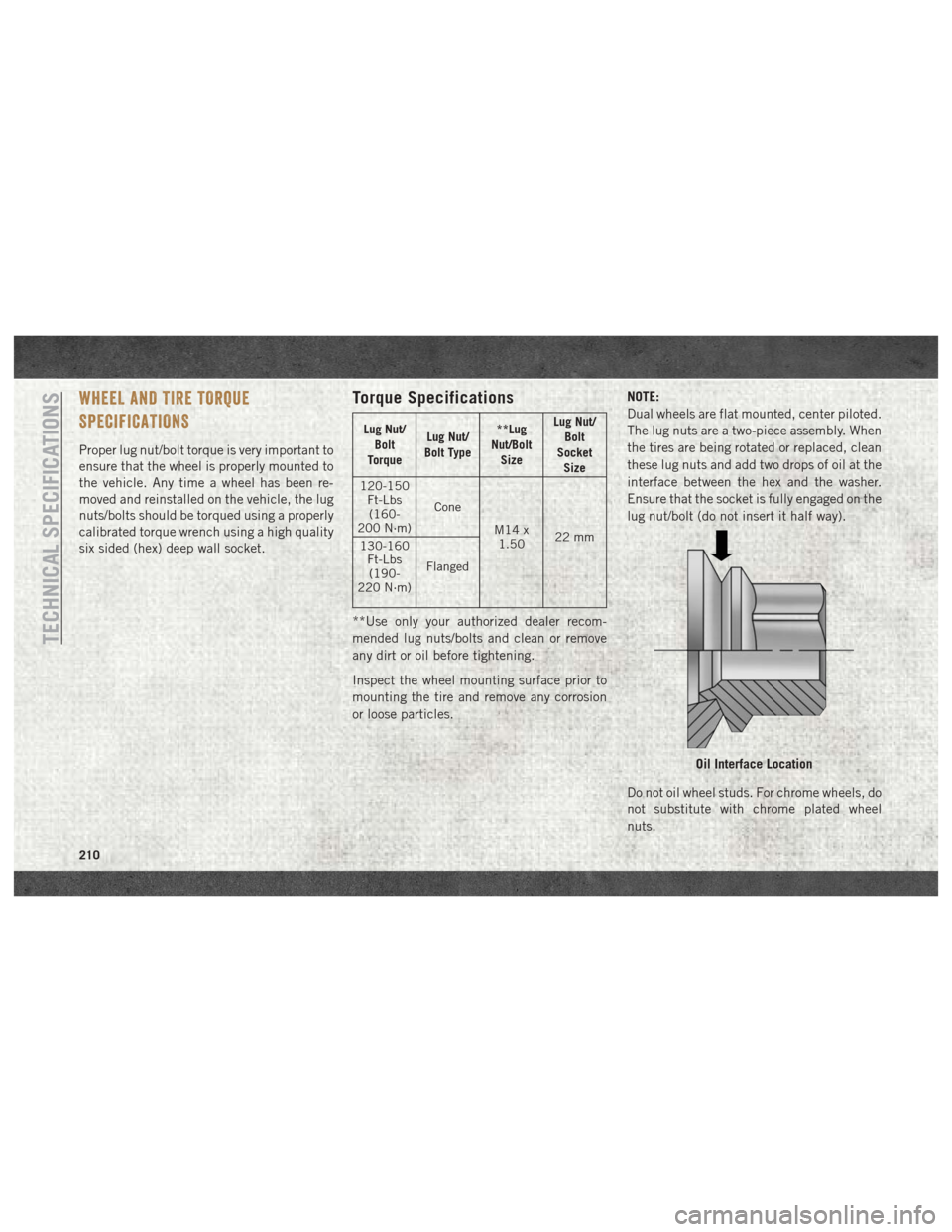
Torque Specifications
Lug Nut/Bolt
Torque Lug Nut/
Bolt Type **Lug
Nut/Bolt Size Lug Nut/
Bolt
Socket Size
120-150 Ft-Lbs(160-
200 N·m) Cone
M14 x1.50 22 mm
130-160
Ft-Lbs(190-
220 N·m) Flanged
**Use only your authorized dealer recom-
mended lug nuts/bolts and clean or remove
any dirt or oil before tightening.
Inspect the wheel mounting surface prior to
mounting the tire and remove any corrosion
or loose particles. NOTE:
Dual wheels are flat mounted, center piloted.
The lug nuts are a two-piece assembly. When
the tires are being rotated or replaced, clean
these lug nuts and add two drops of oil at the
interface between the hex and the washer.
Ensure that the socket is fully engaged on the
lug nut/bolt (do not insert it half way).
Do not oil wheel studs. For chrome wheels, do
not substitute with chrome plated wheel
nuts.
Oil Interface Location
TECHNICAL SPECIFICATIONS
210
Page 213 of 298
Retighten the wheel nuts in the same se-
quence to the torques listed in the table. Go
through the sequence a second time to verify
that specific torque has been achieved. Re-
tighten to specifications after 25 miles
(40 km) and check the lug nut/bolt torque to
be sure that all the lug nuts/bolts are properly
seated against the wheel.
It is recommended that wheel stud nuts be
kept torqued to specifications at all times.
Torque wheel stud nuts to specifications at
each lubrication interval.
All wheel nuts should be tightened occasion-
ally to eliminate the possibility of wheel studs
being sheared or the bolt holes in the wheels
becoming elongated. This is especially im-
portant during the first few hundred miles/
kilometers of operation to allow the wheel
nuts to become properly set. All wheel nuts
should first be firmly seated against the
wheel. The wheel nuts should then be tight-
ened to recommended torque. Tighten the
wheel nuts to final torque in increments.Progress around the bolt circle, tightening
the wheel nut opposite to the wheel nut just
previously tightened until final torque is
achieved.
WARNING!
To avoid the risk of forcing the vehicle off
the jack, do not tighten the lug nuts fully
until the vehicle has been lowered. Failure
to follow this warning may result in per-
sonal injury.
Dual Rear Wheels
Slots in the wheels will assist in properly
orienting the inner and outer wheels. Align
these slots when assembling the wheels for
best access to the tire valve on the inner
wheel. The tires of both dual wheels must be
completely off the ground when tightening to
insure wheel centering and maximum wheel
clamping.
Dual wheel models require a special heavy-
duty lug nut tightening adapter (included
with the vehicle) to correctly tighten the lug
nuts. Also, when it is necessary to remove and
install dual rear wheels, use a proper vehicle
lifting device.
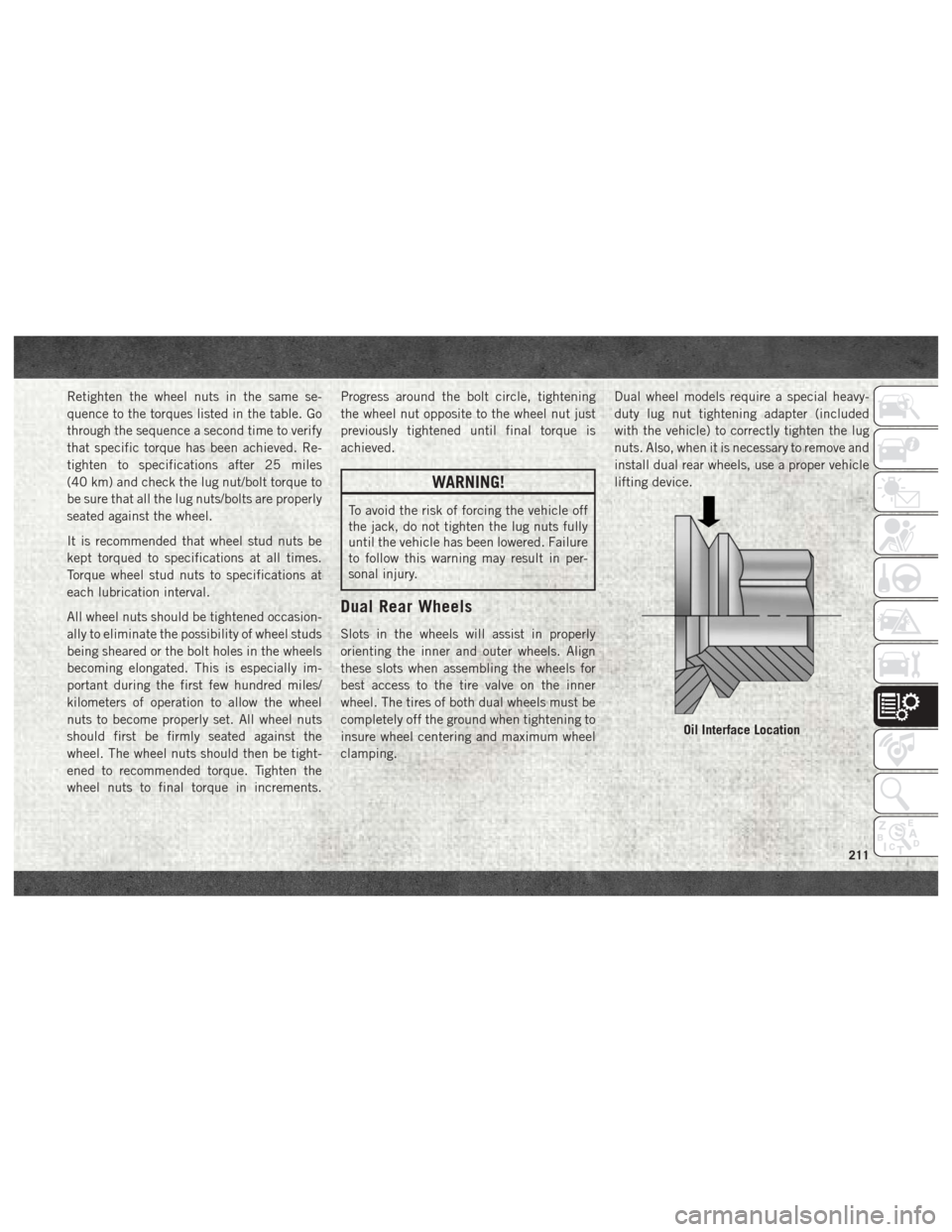
Oil Interface Location
211
Page 215 of 298
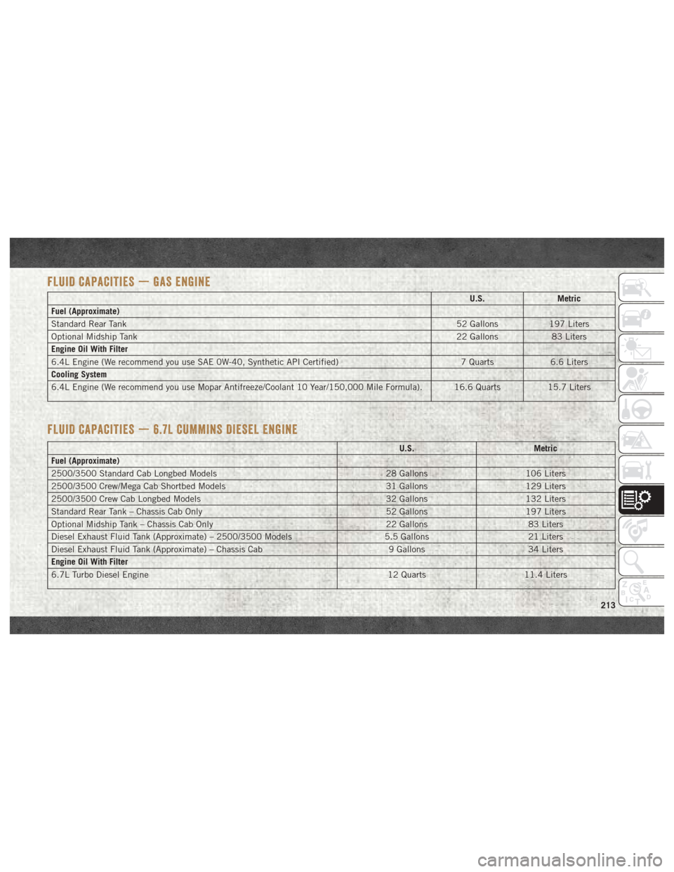
FLUID CAPACITIES — GAS ENGINE
U.S.Metric
Fuel (Approximate)
Standard Rear Tank 52 Gallons197 Liters
Optional Midship Tank 22 Gallons83 Liters
Engine Oil With Filter
6.4L Engine (We recommend you use SAE 0W-40, Synthetic API Certified) 7 Quarts6.6 Liters
Cooling System
6.4L Engine (We recommend you use Mopar Antifreeze/Coolant 10 Year/150,000 Mile Formula). 16.6 Quarts 15.7 Liters
FLUID CAPACITIES — 6.7L CUMMINS DIESEL ENGINE
U.S.Metric
Fuel (Approximate)
2500/3500 Standard Cab Longbed Models 28 Gallons106 Liters
2500/3500 Crew/Mega Cab Shortbed Models 31 Gallons129 Liters
2500/3500 Crew Cab Longbed Models 32 Gallons132 Liters
Standard Rear Tank – Chassis Cab Only 52 Gallons197 Liters
Optional Midship Tank – Chassis Cab Only 22 Gallons83 Liters
Diesel Exhaust Fluid Tank (Approximate) – 2500/3500 Models 5.5 Gallons21 Liters
Diesel Exhaust Fluid Tank (Approximate) – Chassis Cab 9 Gallons34 Liters
Engine Oil With Filter
6.7L Turbo Diesel Engine 12 Quarts11.4 Liters
213
Page 216 of 298
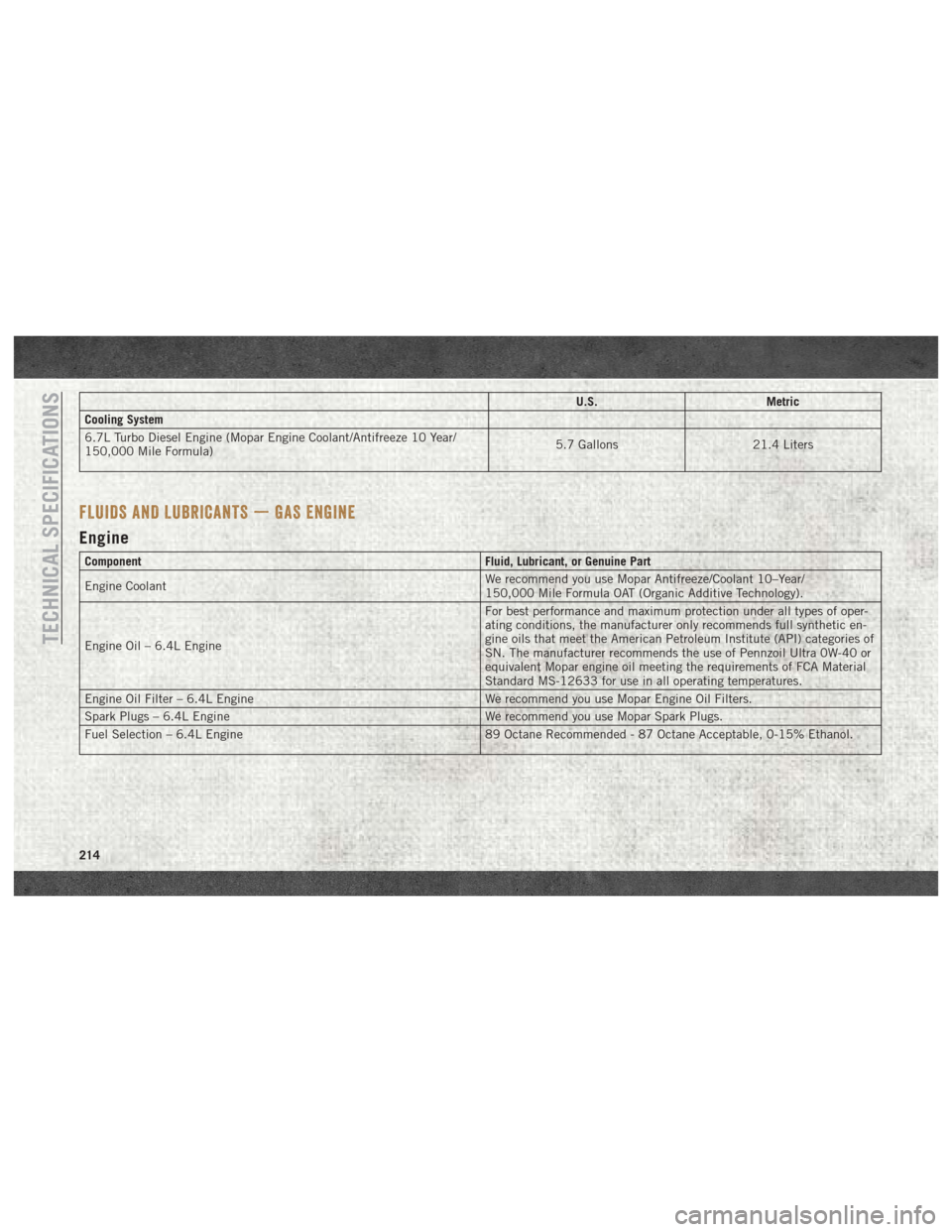
U.S.Metric
Cooling System
6.7L Turbo Diesel Engine (Mopar Engine Coolant/Antifreeze 10 Year/
150,000 Mile Formula) 5.7 Gallons
21.4 Liters
FLUIDS AND LUBRICANTS — GAS ENGINE
Engine
Component Fluid, Lubricant, or Genuine Part
Engine Coolant We recommend you use Mopar Antifreeze/Coolant 10–Year/
150,000 Mile Formula OAT (Organic Additive Technology).
Engine Oil – 6.4L Engine For best performance and maximum protection under all types of oper-
ating conditions, the manufacturer only recommends full synthetic en-
gine oils that meet the American Petroleum Institute (API) categories of
SN. The manufacturer recommends the use of Pennzoil Ultra 0W-40 or
equivalent Mopar engine oil meeting the requirements of FCA Material
Standard MS-12633 for use in all operating temperatures.
Engine Oil Filter – 6.4L Engine We recommend you use Mopar Engine Oil Filters.
Spark Plugs – 6.4L Engine We recommend you use Mopar Spark Plugs.
Fuel Selection – 6.4L Engine 89 Octane Recommended - 87 Octane Acceptable, 0-15% Ethanol.
TECHNICAL SPECIFICATIONS
214